Titus 2008 - 2009 Product Catalog | www.titus ... - Texas Air Products
Titus 2008 - 2009 Product Catalog | www.titus ... - Texas Air Products
Titus 2008 - 2009 Product Catalog | www.titus ... - Texas Air Products

You also want an ePaper? Increase the reach of your titles
YUMPU automatically turns print PDFs into web optimized ePapers that Google loves.
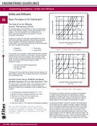
ENGINEERING GUIDELINES<br />
B<br />
B56<br />
TERMINAL CONTROLS AND ACCESSORIES<br />
Engineering Guidelines | Terminals, Controls and Accessories<br />
Typical Problems<br />
Oversizing Terminal<br />
The direct result of oversizing is low air velocity. With the<br />
velocity too low, the damper must operate in a pincheddown<br />
condition most of the time, making control difficult.<br />
The inlet velocity can also be too low for effective operation<br />
of the sensor and controller. Too low a velocity through an<br />
electric heater will cause the safety airflow switch to shut<br />
down the heater. Oversizing fan terminals results in low<br />
fan motor rpm and the potential for under-lubrication of<br />
the motor bearings, resulting in shortened motor life and<br />
additional sound from larger motors (Figure 89).<br />
Capacity Concentrated in Too Few Terminals<br />
When one large terminal serves a space that should be<br />
served by two or more smaller ones, comfort problems can<br />
result. There may be noticeable temperature differences<br />
between rooms, since the thermostat is located in just one<br />
room as at the right. Also, for a given air velocity, the larger<br />
the terminal the more sound power it generates (Figure<br />
90).<br />
Insufficient Space<br />
Carefully planning the locations of the terminals avoids<br />
problems with installation, performance, and maintenance.<br />
In the example shown at the right, the control side of the<br />
terminal is against the wall, making connections difficult and<br />
service almost impossible. The cramped location also creates<br />
the need for close-coupled duct elbows, which reduce<br />
performance (Figure 91).<br />
Improper Discharge Conditions<br />
The duct connections at the discharge end of the terminal<br />
have a major effect on pressure drop. A tee close to the<br />
discharge is especially to be avoided, along with transition<br />
pieces and elbows. Another common error is running too<br />
much flex duct, as at the right. It would have been better to<br />
continue the rectangular duct to the last diffuser, then install<br />
short flex branches (Figure 92).<br />
Improper Inlet Conditions<br />
The arrangement of duct at the terminal inlet affects both<br />
pressure drop and control accuracy.<br />
The conditions shown at the right will create turbulence at<br />
the inlet. This makes it difficult for the sensor to measure<br />
airflow accurately. Although <strong>Titus</strong> velocity sensors correct<br />
for a considerable amount of turbulence, the best practice is<br />
to use straight duct at the inlet the same size or larger than<br />
the inlet (Figure 93).<br />
<strong>Titus</strong> <strong>2008</strong> - <strong>2009</strong> <strong>Product</strong> <strong>Catalog</strong> | <strong>www</strong>.<strong>titus</strong>-hvac.com<br />
Velocity too low for<br />
accurate dampering<br />
Terminal<br />
Tee at<br />
Discharge<br />
Terminal<br />
Large terminal<br />
serves more<br />
than one zone.<br />
Total<br />
damper travel<br />
Velocity too low<br />
for sensor<br />
Velocity too low for<br />
accurate dampering<br />
Figure 89. Low Velocity Effects<br />
Room 101<br />
Too Hot<br />
Figure 90. Too Few Terminals Effect<br />
Controls Coil Connections<br />
Terminal<br />
Figure 91. Installation Affecting Performance<br />
Terminal<br />
Figure 92. Improper Discharge Conditions<br />
Inlet tapped<br />
Tight elbow<br />
into side of duct at inlet<br />
Figure 93. Improper Inlet Conditions<br />
Velocity too low for<br />
electric heater<br />
Room 103<br />
T<br />
Pipe<br />
Chase<br />
Too much<br />
flex duct<br />
Supply duct<br />
smaller than inlet