Titus 2008 - 2009 Product Catalog | www.titus ... - Texas Air Products
Titus 2008 - 2009 Product Catalog | www.titus ... - Texas Air Products
Titus 2008 - 2009 Product Catalog | www.titus ... - Texas Air Products

You also want an ePaper? Increase the reach of your titles
YUMPU automatically turns print PDFs into web optimized ePapers that Google loves.
ENGINEERING GUIDELINES<br />
B<br />
B42<br />
TERMINAL CONTROLS AND ACCESSORIES<br />
Engineering Guidelines | Terminals, Controls and Accessories<br />
Types of Controls<br />
Reaction to Duct Pressure Controls<br />
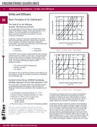
Pressure Independent<br />
With this type of control the terminal maintains the flow<br />
rate required to handle the heating or cooling load,<br />
regardless of system pressure fluctuations. It is the best<br />
choice where the system pressure will vary extensively<br />
and where precise control is essential. Key components in<br />
pressure independent control are the velocity sensor, which<br />
furnishes a continuous reading of the air velocity through<br />
the terminal, and the velocity controller, which processes<br />
this information along with signals from the thermostat. In<br />
the chart (Figure 55), vertical lines AB and EF represent<br />
minimum and maximum cfm settings which are adjustable<br />
at the controller. Line CD represents any cfm setting<br />
maintained by the controller in response to the thermostat.<br />
The damper will open and close as needed to hold the cfm<br />
constant up and down this vertical line for the full range<br />
of pressure drops shown. Notice that the vertical cfm lines<br />
are cut off by the diagonal line AE, which represents the<br />
pressure drop from inlet to outlet with the damper wide<br />
open. This is the minimum DP shown in our data.<br />
Pressure Dependent<br />
A terminal with this type of control is designed for those<br />
applications where neither pressure independence nor<br />
cfm limit regulation is required. An example is a variable<br />
volume makeup air supply in which the downstream duct<br />
pressure is held constant by other controls. The terminal<br />
consists essentially of a casing, a damper and a damper<br />
actuator. There is no controller and no velocity sensor; the<br />
damper moves in direct response to the thermostat or other<br />
signal input. The line AB (Figure 56) shows the typical<br />
performance characteristic. It represents a given damper<br />
setting, with the flow rate varying as the square root of the<br />
static pressure drop through the terminal. This, of course,<br />
is typical of any damper or fixed orifice. Lines CD and EF<br />
represent random additional settings as the damper opens<br />
to the full open position line GH. Line GH is the minimum<br />
pressure loss of the assembly.<br />
Most of the control types shown here have certain principle<br />
elements in common:<br />
Room Thermostat or Sensor<br />
The thermostat contains not only a temperature sensing<br />
element, but also a means of changing the setpoint. The<br />
room sensor used with the direct digital control system is<br />
simply an electronic temperature sensor; setpoint changes<br />
are handled along with other signal processing in the digital<br />
controller.<br />
Velocity Sensor<br />
Mounted in the inlet of the terminal, this device senses air<br />
velocity, which can easily be converted to airflow rate. The<br />
sensor’s signal provides feedback to monitor and directs the<br />
operation of the controller and damper actuator.<br />
<strong>Titus</strong> <strong>2008</strong> - <strong>2009</strong> <strong>Product</strong> <strong>Catalog</strong> | <strong>www</strong>.<strong>titus</strong>-hvac.com<br />
Note: Excessive airflow may lead to excessive noise. Pressure<br />
independent control has Minimum less opportunity Variablefor<br />
Maximum variable (and<br />
unwanted) sounds in the cfmoccupied<br />
cfm spaces. cfm<br />
Setting Setting Setting<br />
Pressure Drop in w.g.<br />
Pressure Drop in w.g.<br />
6.00<br />
4.00<br />
6.00<br />
2.00<br />
4.00<br />
1.00<br />
0.802.00<br />
0.60<br />
1.00<br />
0.400.80<br />
0.60<br />
0.20<br />
0.40<br />
Pressure Drop in w.g.<br />
0.100.20<br />
0.08<br />
0.06<br />
0.10<br />
0.08<br />
0.040.06<br />
0.020.04<br />
6.00<br />
4.006.00<br />
4.00<br />
2.00<br />
2.00<br />
1.00<br />
1.00<br />
0.60<br />
0.60<br />
0.40<br />
0.40<br />
Pressure Drop in w.g.<br />
0.20<br />
0.20<br />
0.10 0.10A A<br />
0.06 0.06<br />
0.04 0.04<br />
C C<br />
0.02 0.02<br />
Controller<br />
Commands from the thermostat or room sensor, together<br />
with feedback from the velocity sensor, are processed in<br />
the controller to regulate the damper actuator. Operation is<br />
pressure independent.<br />
Damper Actuator<br />
Minumum SP, Wide Open Damper<br />
Figure 55. Pneumatic Pressure Independent<br />
E E<br />
0.01 0.01<br />
100 100<br />
200 200<br />
Minimum B<br />
cfm<br />
Setting<br />
A<br />
B<br />
GG<br />
Damper<br />
Setting Damper<br />
#1Setting<br />
#1<br />
Damper<br />
Damper<br />
Setting<br />
Setting<br />
#2<br />
#2<br />
Damper<br />
Damper<br />
Setting Setting<br />
#3 #3<br />
Damper<br />
Setting<br />
Open<br />
300 300 400 400 500 600<br />
700 800 1000<br />
<strong>Air</strong><br />
<strong>Air</strong><br />
Flow,<br />
Flow,<br />
cfm<br />
cfm<br />
Variable D<br />
cfm<br />
Setting<br />
Maximum F<br />
cfm<br />
Setting<br />
Figure 56. Pneumatic Pressure Dependent<br />
The damper actuator opens and closes the damper to<br />
change the airflow, or to hold it constant, as dictated by the<br />
controller.<br />
D<br />
C<br />
F<br />
E<br />
Minumum SP, Wide Open Damper<br />
0.010.02<br />
100 200<br />
A<br />
300 400 500 600700<br />
800 1000<br />
0.01<br />
100<br />
<strong>Air</strong> Flow, cfm<br />
200 300 400<br />
<strong>Air</strong> Flow, cfm<br />
500 600700<br />
800 1000<br />
C<br />
E<br />
B<br />
B<br />
D<br />
D<br />
F<br />
F<br />
H