Titus 2008 - 2009 Product Catalog | www.titus ... - Texas Air Products
Titus 2008 - 2009 Product Catalog | www.titus ... - Texas Air Products
Titus 2008 - 2009 Product Catalog | www.titus ... - Texas Air Products

Create successful ePaper yourself
Turn your PDF publications into a flip-book with our unique Google optimized e-Paper software.
ENGINEERING GUIDELINES<br />
B<br />
B46<br />
TERMINAL CONTROLS AND ACCESSORIES<br />
Engineering Guidelines | Terminals, Controls and Accessories<br />
Operation of a<br />
Velocity Controller<br />
Definitions of Terms<br />
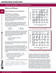
The controller setpoint is the cfm<br />
setting that the control system is<br />
calling for at any given moment. At<br />
that setpoint the damper opening may<br />
vary widely to compensate for any duct<br />
pressure changes reported by the inlet<br />
sensor, and thus hold the cfm constant.<br />
With pneumatic systems, the setpoint,<br />
11 psi in the example (Figure 69),<br />
can be reset by the action of the<br />
thermostat anywhere between the<br />
maximum and minimum cfm settings<br />
of the controller. The corresponding<br />
thermostat output pressures are called<br />
the start and stop points. The range<br />
of possible setpoints between the start<br />
and stop points is called the reset<br />
span, 8 to 13 psi in the example shown<br />
here.<br />
The thermostat may also control an<br />
auxiliary piece of equipment, such as<br />
a proportioning valve on a hot water<br />
coil, shown here modulating over<br />
a range of 3 to 8 psi, in sequence<br />
with the reset span of the controller.<br />
The overall range over which the<br />
thermostat controls these devices is<br />
its proportional band or total throttling<br />
range, 3 to 13 psi in this example.<br />
Thermostat Sensitivity<br />
This is the change in output signal<br />
caused by a change in room<br />
temperature. This rating (Figure 70)<br />
is usually 1°F = 2.5 psi for pneumatic<br />
systems. Electronic systems have a<br />
wide variance in output responses.<br />
Hysteresis<br />
This is the failure of an object to return<br />
to its original position after a force has<br />
moved or deflected it. For example, in<br />
some velocity controllers (Figure 71)<br />
the cfm setting increases along the<br />
lower curved line and decreases along<br />
the upper curved line. At the setpoint,<br />
the cfm may be either A or B.<br />
<strong>Titus</strong> <strong>2008</strong> - <strong>2009</strong> <strong>Product</strong> <strong>Catalog</strong> | <strong>www</strong>.<strong>titus</strong>-hvac.com<br />
13<br />
8<br />
100<br />
% Max. Flow<br />
0<br />
Max. gpm<br />
Set<br />
Point<br />
(DDES)<br />
73 75 77<br />
Room Temperature<br />
Total Throttling Range<br />
of Thermostat<br />
Hot<br />
Water<br />
Valve<br />
Modulation<br />
Min. cfm<br />
Start<br />
Point<br />
3 8<br />
(Cooling)<br />
Thermostat Output, psi<br />
Figure 69. Set Point Example<br />
Set<br />
Point<br />
Thermostat Output, psi<br />
Figure 70. Thermostat Sensitivity Example Figure 71. Hysteresis Example<br />
cfm<br />
Reset Span<br />
of Controller<br />
(Cooling)<br />
B<br />
A<br />
Set<br />
Point<br />
11<br />
Min<br />
8<br />
13<br />
Max. cfm<br />
Stop<br />
Point<br />
13<br />
Max