SBIG Self Guided Spectrograph (SGS) Operating ... - Sbig.com
SBIG Self Guided Spectrograph (SGS) Operating ... - Sbig.com
SBIG Self Guided Spectrograph (SGS) Operating ... - Sbig.com
- No tags were found...

You also want an ePaper? Increase the reach of your titles
YUMPU automatically turns print PDFs into web optimized ePapers that Google loves.
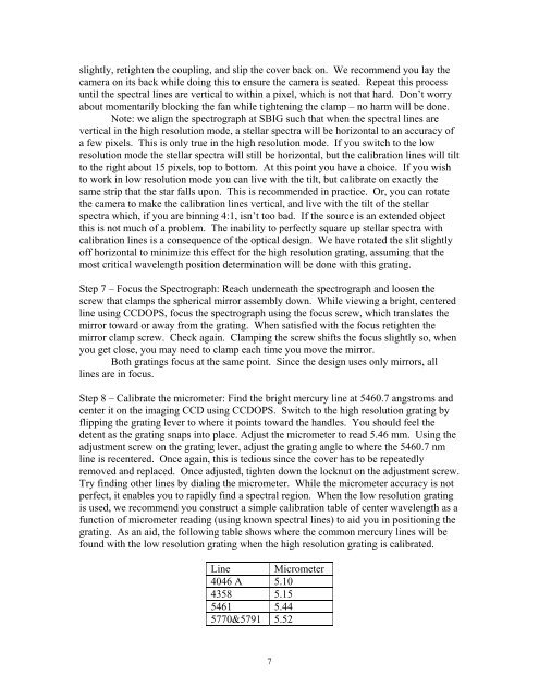
slightly, retighten the coupling, and slip the cover back on. We re<strong>com</strong>mend you lay thecamera on its back while doing this to ensure the camera is seated. Repeat this processuntil the spectral lines are vertical to within a pixel, which is not that hard. Don’t worryabout momentarily blocking the fan while tightening the clamp – no harm will be done.Note: we align the spectrograph at <strong>SBIG</strong> such that when the spectral lines arevertical in the high resolution mode, a stellar spectra will be horizontal to an accuracy ofa few pixels. This is only true in the high resolution mode. If you switch to the lowresolution mode the stellar spectra will still be horizontal, but the calibration lines will tiltto the right about 15 pixels, top to bottom. At this point you have a choice. If you wishto work in low resolution mode you can live with the tilt, but calibrate on exactly thesame strip that the star falls upon. This is re<strong>com</strong>mended in practice. Or, you can rotatethe camera to make the calibration lines vertical, and live with the tilt of the stellarspectra which, if you are binning 4:1, isn’t too bad. If the source is an extended objectthis is not much of a problem. The inability to perfectly square up stellar spectra withcalibration lines is a consequence of the optical design. We have rotated the slit slightlyoff horizontal to minimize this effect for the high resolution grating, assuming that themost critical wavelength position determination will be done with this grating.Step 7 – Focus the <strong>Spectrograph</strong>: Reach underneath the spectrograph and loosen thescrew that clamps the spherical mirror assembly down. While viewing a bright, centeredline using CCDOPS, focus the spectrograph using the focus screw, which translates themirror toward or away from the grating. When satisfied with the focus retighten themirror clamp screw. Check again. Clamping the screw shifts the focus slightly so, whenyou get close, you may need to clamp each time you move the mirror.Both gratings focus at the same point. Since the design uses only mirrors, alllines are in focus.Step 8 – Calibrate the micrometer: Find the bright mercury line at 5460.7 angstroms andcenter it on the imaging CCD using CCDOPS. Switch to the high resolution grating byflipping the grating lever to where it points toward the handles. You should feel thedetent as the grating snaps into place. Adjust the micrometer to read 5.46 mm. Using theadjustment screw on the grating lever, adjust the grating angle to where the 5460.7 nmline is recentered. Once again, this is tedious since the cover has to be repeatedlyremoved and replaced. Once adjusted, tighten down the locknut on the adjustment screw.Try finding other lines by dialing the micrometer. While the micrometer accuracy is notperfect, it enables you to rapidly find a spectral region. When the low resolution gratingis used, we re<strong>com</strong>mend you construct a simple calibration table of center wavelength as afunction of micrometer reading (using known spectral lines) to aid you in positioning thegrating. As an aid, the following table shows where the <strong>com</strong>mon mercury lines will befound with the low resolution grating when the high resolution grating is calibrated.Line Micrometer4046 A 5.104358 5.155461 5.445770&5791 5.527