Gas-fired water boiler - Weil-McLain
Gas-fired water boiler - Weil-McLain
Gas-fired water boiler - Weil-McLain
- No tags were found...

You also want an ePaper? Increase the reach of your titles
YUMPU automatically turns print PDFs into web optimized ePapers that Google loves.
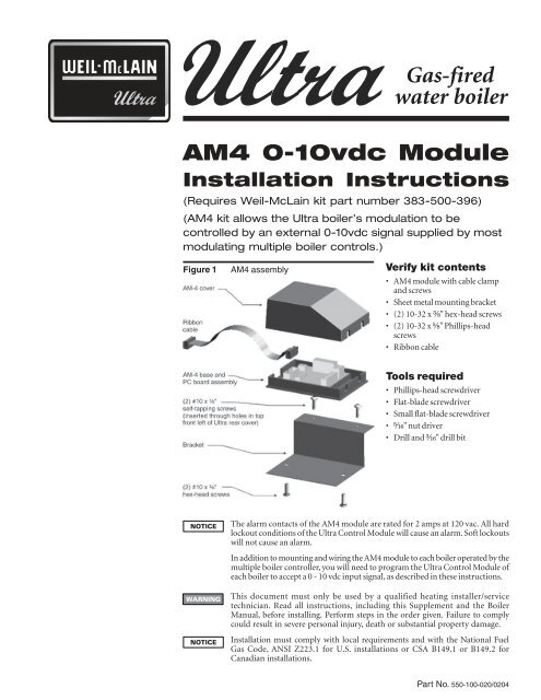
<strong>Gas</strong>-<strong>fired</strong><strong>water</strong> <strong>boiler</strong>AM4 0-10vdc ModuleInstallation Instructions(Requires <strong>Weil</strong>-<strong>McLain</strong> kit part number 383-500-396)(AM4 kit allows the Ultra <strong>boiler</strong>’s modulation to becontrolled by an external 0-10vdc signal supplied by mostmodulating multiple <strong>boiler</strong> controls.)Figure 1AM4 assemblyVerify kit contents• AM4 module with cable clampand screws• Sheet metal mounting bracket• (2) 10-32 x ³⁄₈" hex-head screws• (2) 10-32 x ⁵⁄₈" Phillips-headscrews• Ribbon cableTools required• Phillips-head screwdriver• Flat-blade screwdriver• Small flat-blade screwdriver• ⁵⁄₁₆" nut driver• Drill and ³⁄₁₆" drill bitThe alarm contacts of the AM4 module are rated for 2 amps at 120 vac. All hardlockout conditions of the Ultra Control Module will cause an alarm. Soft lockoutswill not cause an alarm.In addition to mounting and wiring the AM4 module to each <strong>boiler</strong> operated by themultiple <strong>boiler</strong> controller, you will need to program the Ultra Control Module ofeach <strong>boiler</strong> to accept a 0 - 10 vdc input signal, as described in these instructions.This document must only be used by a qualified heating installer/servicetechnician. Read all instructions, including this Supplement and the BoilerManual, before installing. Perform steps in the order given. Failure to complycould result in severe personal injury, death or substantial property damage.Installation must comply with local requirements and with the National Fuel<strong>Gas</strong> Code, ANSI Z223.1 for U.S. installations or CSA B149.1 or B149.2 forCanadian installations.Part No. 550-100-020/0204
GAS-FIRED WATER BOILER — AM4 Module InstructionsInstallation procedureElectrical shock hazard — Turn off powerto the <strong>boiler</strong> before proceeding with theinstallation. Failure to comply could resultin severe personal injury, death orsubstantial property damage.Mount and wire AM4 module1. Remove <strong>boiler</strong> front panel by removing the twoknurled screws at the bottom with a flat bladescrewdriver. Once the knurled screws are removed,lift front panel of <strong>boiler</strong> and pull forward to remove.2. Remove top front plastic cover by removing the fourPhillips-head screws securing it.3. Insert a small flat-blade screwdriver into slot onbottom of AM4 module (at tapered end of modulecover) and gently pry off the cover.4. With AM4 cover removed, carefully insert either endof the ribbon cable into the AM4 plug. Cable will fitinto the cutout on the end of the module cover andbase. See Figure 2.on the bracket by inserting the two 10-32 x ³⁄₈" hexheadscrews (supplied) from the bottom of the bracketas shown. See Figure 3.Figure 3AM4 mounted to bracketFigure 2AM4 wiring connections8. Use the metal bracket as a template, and mark thehole locations on the front left side of the Ultra <strong>boiler</strong>rear cover as shown in Figure 4.Figure 4Mark and drill mounting holes5. Route multiple <strong>boiler</strong> controller wires and alarm wiresthrough the Ultra <strong>boiler</strong> cable ways, along with theother wiring. Strip ends and attach to the terminalsshown in Figure 2. Use the cable clamp supplied inthe AM4 kit to secure the alarm wires to the module.6. Fasten the AM4 cover on the module.7. Place the AM4 module on the mounting bracket,oriented as shown in Figure 1, page 1. Secure in place9. The AM4 bracket must be mounted in the positionshown for the ribbon cable to reach the Ultra control2Part number 550-100-020/0204
GAS-FIRED WATER BOILER — AM4 Module InstructionsInstallation procedure (continued)module socket.10. Drill a ³⁄₁₆" hole in each of the marked locations.11. Position the AM4 mounting bracket under the toprear panel as shown in Figure 5. Secure the bracket inplace by inserting the two 10-32 x ⁵⁄₈" Phillips-head,self-tapping screws (provided) through the rear panelholes and into the bracket holes.Figure 5AM4 mounted in positionProgram <strong>boiler</strong> control moduleThe factory default setting for operationof the Ultra Control Module is forthermostat control. The module must beprogrammed, as described in the following,to operate from a 0 - 10 vdc input signal tooperate correctly with the AM4 module.1. Follow instructions in the Ultra Boiler Manual andthe Ultra Control Supplement to install, set up andadjust the <strong>boiler</strong>.12. Plug the end of the ribbon cable into the empty socketon the left end of the Ultra control module.13. Replace the top front cover and secure with the fourscrews.14. Restore power to the <strong>boiler</strong>.Differences from standard operation1. The AM4 module responds to a signal from themultiple <strong>boiler</strong> controller. The <strong>boiler</strong> will not cycle onthermostat action, but on the control signal fromthe AM4 module to the Ultra Control Module. Totest <strong>boiler</strong> operation, you will need to operate themultiple <strong>boiler</strong> controller to signal the <strong>boiler</strong> to initiatea call for heat to test the <strong>boiler</strong> and controls.2. Parameter readouts (Ultra Control Module):• Parameter 4 will not show outside temperature.The Ultra Control Module does not use anoutside sensor when using an AM4.• Parameter 6 will not show target outlet <strong>water</strong>temperature. Water temperature control isperformed by the multiple <strong>boiler</strong> controller.Program control module for AM4 input1. You must program the Ultra Control Module toaccept the 0 - 10 vdc input signal from the AM4 asdescribed on the next page.Do not attempt to revise any other controlsettings except those covered in the UltraControl Supplement. Perform only therevisions described in this document andthe Ultra Control Supplement. Failure tocomply could result in erratic or unreliableoperation of the <strong>boiler</strong>.Part number 550-100-020/0204 3
GAS-FIRED WATER BOILER — AM4 Module InstructionsInstallation procedure (continued)Program control module for AM4 input(continued)2. Once the instructions for preparation of the <strong>boiler</strong> arecompleted, activate code mode on the Ultra Control Moduleas follows:a. Press and hold . Continue holding and pressalso. Hold both buttons for 2 seconds or longer.The module readout will change to [CODE]. Release theand buttons.b. Press once. The module readout will show [C - XX],where the “XX” will be a random number.c. Use or to change the last two digits until thedisplay shows [C - 05]. (To change numbers one unit at atime, tap or . To make the number changequickly, hold down or .)d. When the display shows [C - 05], press to enter thecode number.3. Revise parameter 34 as follows:a. Once the code has been stored, change to the “Parameter”mode by pressing until parameter mode is selected.b. Press repeatedly until the readout shows [P . 34].The readout sequence as you press the button will be:[1 140], [2 .01], [3 .01], [4 190], [P . 05], [P . 06],[P . 07], etc.The readout will continue to show “P . “ followed by a twodigitnumber that increases each time you press .The actual parameter values displayed may vary,depending on the application. The parametersequence will always occur in the order shown.c. When the readout shows [P . 34], stop pushing thebutton. Wait a few seconds and the display will show thecurrent setting for parameter 34 in the right two displayspaces.d. Press or to change the value until the displayshows [- - 04].e. Save the change by pressing .To return the <strong>boiler</strong> to thermostat operation,perform the above steps, but set parameter 34 to“00” instead (display shows [- - 00] instead of[- - 04]).4. Exit code mode by pressing once.Test and verify <strong>boiler</strong>/control operation1. Follow the Ultra Boiler Manual and Ultra Control Supplementinstructions to test operation of the <strong>boiler</strong> and its controls. Toinitiate a call for heat you will have to operate the multiple<strong>boiler</strong> controller to activate the <strong>boiler</strong>.2. Verify the <strong>boiler</strong> modulates correctly by adjusting the multiple<strong>boiler</strong> controller.3. The control response to the 0 - 10 vdc signal will be:• Boiler on for voltage above 0.5 vdc.• Boiler at low fire at voltage between 0.5 vdc and 1.8 vdc.• Boiler at high fire at voltage of 10 vdc.• Boiler modulates between high fire and low fire for voltagebetween 1.8 and 10 vdc.Test AM4 alarm circuit (if used)The AM4 will close the alarm relay contacts on anyhard lockout of the Ultra Control Module. It willnot send an alarm on soft lockouts.1. With the <strong>boiler</strong> electrical power OFF, unplug one of the electricalconnectors to either the supply or return temperature sensor.2. Restore power to <strong>boiler</strong> and allow to cycle.3. The Ultra Control Module should enter a hard lockout, causingthe AM4 alarm relay to close. The remote alarm should activate.4. Disconnect <strong>boiler</strong> power and replace the sensor lead removedin step 1.5. Restore power and verify <strong>boiler</strong> operation before leaving thejobsite.Replace <strong>boiler</strong> components1. Replace all <strong>boiler</strong> components and <strong>boiler</strong> front jacket panel.Replace <strong>boiler</strong> jacket front door after servicing. The<strong>boiler</strong> front door must be securely fastened to the<strong>boiler</strong> to prevent <strong>boiler</strong> from drawing air from insidethe <strong>boiler</strong> room. This is particularly important if the<strong>boiler</strong> is located in the same room as other appliances.Failure to keep the door securely fastened could resultin severe personal injury or death.4 Part Number 550-100-020/0204