User's Information Manual - Weil-McLain
User's Information Manual - Weil-McLain
User's Information Manual - Weil-McLain

You also want an ePaper? Increase the reach of your titles
YUMPU automatically turns print PDFs into web optimized ePapers that Google loves.
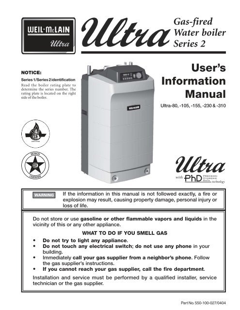
Gas-firedWater boilerSeries 2NOTICE:Series 1/Series 2 identificationRead the boiler rating plate todetermine the series number. Therating plate is located on the rightside of the boiler.User’s<strong>Information</strong><strong>Manual</strong>Ultra-80, -105, -155, -230 & -310withIf the information in this manual is not followed exactly, a fire orexplosion may result, causing property damage, personal injury orloss of life.Do not store or use gasoline or other flammable vapors and liquids in thevicinity of this or any other appliance.WHAT TO DO IF YOU SMELL GAS• Do not try to light any appliance.• Do not touch any electrical switch; do not use any phone in yourbuilding.• Immediately call your gas supplier from a neighbor’s phone. Followthe gas supplier’s instructions.• If you cannot reach your gas supplier, call the fire department.Installation and service must be performed by a qualified installer, servicetechnician or the gas supplier.Part No. 550-100-027/0404
GAS-FIRED WATER BOILER SERIES 2 — User’s <strong>Information</strong> <strong>Manual</strong>Please read this page firstHazard definitionsThe following defined terms are used throughout this manual to bring attention to the presenceof hazards of various risk levels or to important information concerning the life of the product.Indicates presence of hazards that will cause severe personal injury, death orsubstantial property damage.Indicates presence of hazards that can cause severe personal injury, death orsubstantial property damage.Indicates presence of hazards that will or can cause minor personal injury orproperty damage.Indicates special instructions on installation, operation or maintenance that areimportant but not related to personal injury or property damage.Boiler service andmaintenanceThe Boiler manual is for use only by a qualified heating installer/servicetechnician. Refer only to this User’s <strong>Information</strong> <strong>Manual</strong> for your reference.Improper installation, adjustment, alteration, service or maintenance can causeproperty damage, personal injury (exposure to hazardous materials) or loss oflife. Installation and service must be performed by a qualified installer, serviceagency or the gas supplier (who must read and follow the supplied instructionsbefore installing, servicing, or removing this boiler. This boiler contains materialsthat have been identified as carcinogenic, or possibly carcinogenic, to humans).When calling or writing about the boiler— Please have the boiler model numberfrom the boiler rating label and the CP number from the boiler jacket.How to use thismanual . . .2Part number 550-100-027/0404
GAS-FIRED WATER BOILER SERIES 2 — User’s <strong>Information</strong> <strong>Manual</strong>STOP!! — Read before proceedingFailure to adhere to the guidelines on this page can result in severepersonal injury, death or substantial property damage.Boiler service and maintenance —• To avoid electric shock, disconnect electrical supply beforeperforming maintenance.• To avoid severe burns, allow boiler to cool before performingmaintenance.• You must maintain the boiler as outlined in this manual and have theboiler started up and serviced at least annually by a qualifiedservice technician to ensure boiler/system reliability.Boiler operation —• Do not block flow of combustion or ventilation air to boiler. Thisboiler is equipped with a control which will automatically shut downthe boiler should air or vent be blocked. If vent or air blockage iseasily accessible and removable, remove it. The boiler should attemptto restart. If blockage is not obvious or cannot be removed, have theboiler and system checked by a qualified service technician.• Do not allow contaminated air to enter the boiler air inlet pipe. Seepage 4 for details.• Should overheating occur or gas supply fail to shut off, do notturn off or disconnect electrical supply to boiler. Instead, shut off thegas supply at a location external to the appliance.• Do not use this boiler if any part has been under water.Immediately call a qualified service technician to inspect the boilerand to replace any part of the control system and any gas control, whichhas been under water.Boiler water —• Have boiler water chemistry checked at least annually by a qualifiedservice technician.• DO NOT use petroleum-based cleaning or sealing compounds inboiler system. Gaskets and seals in the system may be damaged. Thiscan result in substantial property damage.• DO NOT use "homemade cures" or "boiler patent medicines".Serious damage to boiler, personnel and/or property may result.• Continual fresh makeup water will reduce boiler life. Mineral buildupin boiler heat exchanger reduces heat transfer, overheats the metal,and causes heat exchanger failure. Addition of oxygen can cause internalcorrosion in system components. Leaks in boiler or piping must berepaired at once to prevent makeup water.• Do not add cold water to hot boiler. Thermal shock can cause boilerheat exchanger to crack.Part number 550-100-027/0404 3
GAS-FIRED WATER BOILER SERIES 2 — User’s <strong>Information</strong> <strong>Manual</strong>Prevent combustion air contaminationIf the boiler combustion air inlet is located in any arealikely to cause contamination, or if products whichwould contaminate the air cannot be removed, youmust have the combustion air and vent repipedand terminated to another location. Contaminatedcombustion air will damage the boiler, resulting inpossible severe personal injury, death or substantialproperty damage.Do not operate an Ultra boiler if its combustionair inlet is located in a laundry room or pool facility,for example. These areas will always contain hazardouscontaminants.Pool and laundry products and common householdand hobby products often contain fluorine or chlorinecompounds. When these chemicals pass through theboiler, they can form strong acids. The acid can eatthrough the boiler wall, causing serious damage andpresenting a possible threat of flue gas spillage or boilerwater leakage into the building.Please read the information listed below. Ifcontaminating chemicals will be present near thelocation of the boiler combustion air inlet, have yourinstaller pipe the boiler combustion air and vent toanother location, per the Boiler manual.4Part number 550-100-027/0404
GAS-FIRED WATER BOILER SERIES 2 — User’s <strong>Information</strong> <strong>Manual</strong>Perform maintenance per schedule belowFollow the maintenance procedures given throughout this manual. Failure to perform the service and maintenance orfollow the directions in this manual could result in damage to the boiler or system, resulting in severe personal injury,death or substantial property damage.Part number 550-100-027/0404 5
GAS-FIRED WATER BOILER SERIES 2 — User’s <strong>Information</strong> <strong>Manual</strong>Maintenance proceduresBoiler must beserviced andmaintainedThe boiler must be inspected and started annually, at the beginning of the heatingseason, by a qualified service technician. In addition, the maintenance and careof the boiler designated on page 5 and explained on pages 6 through 9 must beperformed to assure maximum boiler efficiency and reliability. Failure to serviceand maintain the boiler and system could result in equipment failure, causingpossible severe personal injury, death or substantial property damage.The following information provides detailed instructions for completing themaintenance items listed in the maintenance schedule, page 5. In addition tothis maintenance, the boiler must be serviced and started up at the beginning ofeach heating season by a qualified service technician.DailyCheck boiler areaTo prevent potential of severe personal injury, death or substantial propertydamage, eliminate all materials discussed below from the boiler vicinity and thevicinity of boiler combustion air inlet. If contaminants are found:Remove products immediately from the area. If they have been there for anextended period, call a qualified service technician to inspect the boiler forpossible damage from acid corrosion.If products cannot be removed, immediately call a qualified service technicianto repipe vent and air piping and locate vent termination/air intake away fromcontaminated areas.1. Combustible/flammable materials — Do not store combustible materials, gasoline orany other flammable vapors or liquids near the boiler. Remove immediately if found.2. Air contaminants — Products containing chlorine or fluorine, if allowed to contaminatethe boiler intake air, will cause acidic condensate in the boiler. This will cause significantdamage to the boiler if allowed to continue. Read the list of potential materials listed onpage 4 of this manual. If any of these products are in the room from which the boilertakes its combustion air, they must be removed immediately or the boiler combustion air(and vent termination) must be relocated to another area. See WARNING above.Check air openings 1. Verify that combustion and ventilation air openings to the boiler room and/or buildingare open and unobstructed.2. Verify that boiler vent discharge and air intake are clean and free of obstructions. Removeany debris on the air intake or flue exhaust openings. If removing the debris does notallow the boiler to operate correctly afterwards, contact your qualifed service technicianto inspect the boiler and vent/air systems.Check pressure/temperature gaugeVerify boiler frontdoor is securely inplace1. Make sure the pressure reading on the boiler pressure/temperature gauge does not exceed24 psig. Higher pressure may indicate a problem with the expansion tank.2. Contact a qualified service technician if problem persists.1. Visually inspect boiler front door to be sure it is sealed all around its perimeter. Verify thatthe two lower thumb screws are tight.Replace boiler jacket front door after servicing. The boiler front door must besecurely fastened to the boiler to prevent boiler from drawing air from insidethe boiler room. This is particularly important if the boiler is located in thesame room as other appliances. Failure to keep the door securely fastened couldresult in severe personal injury or death.6Part number 550-100-027/0404
GAS-FIRED WATER BOILER SERIES 2 — User’s <strong>Information</strong> <strong>Manual</strong>Maintenance procedures (continued)MonthlyCheck vent piping1. Visually inspect the flue gas vent piping for any signs of blockage, leakage or deteriorationof the piping. Notify your qualified service technician at once if you find any problem.Failure to inspect the vent system as noted above and have it repaired by aqualifed service technician can result in vent system failure, causing severepersonal injury or death.Check air piping 1. Visually inspect the air inlet elbow to be sure it is unobstructed. Inspect entire length ofair piping to ensure piping is intact and all joints are properly sealed.2. Call your qualified service technician if you notice any problems.Check relief valve 1. Inspect the boiler relief valve and the relief valve discharge pipe for signs of weeping orleakage.2. If the relief valve often weeps, the expansion tank may not be working properly.Immediately contact your qualified service technician to inspect the boiler and system.Check condensatedrain system1. While the boiler is running, check the discharge end of the condensate drain tubing andthe open top of the condensate tee at the boiler (see lower right illustration, page 11, forlocation of tee). Make sure no flue gas is escaping from the condensate drain tubing or teeby holding your fingers in front of the opening.2. If you notice flue gas escaping, this indicates a dry condensate drain trap. See step 4 forprocedure to fill trap. Call your qualified service technician to inspect the boiler andcondensate line and refill the condensate trap if problem persists regularly.Under some circumstances an Ultra vent system may not produce enoughcondensate to keep the condensate trap full of liquid. If the trap is not full, smallamounts of flue products can be emitted into the boiler room through thecondensate drain line or tee. Follow procedure below to fill trap.3. Verify that the condensate drain line is unobstructed by slowly pouring water into the topof the PVC tee on the side of the boiler. The water should run out the end of the condensatedrain line. If the water does not run out, call your qualified service technician to inspectthe boiler and clean or replace the condensate drain line.4. To fill condensate trap, if necessary, temporarily plug the end of the condensate drain line.Then slowly pour water into the ½ inch plastic tee on boiler right side. Pour until waterfills drain line, then overflows into the boiler trap tubing. When water fills up to top of ½inch tee, stop filling. Remove temporary plug from end of condensate drain line.Check automaticair vents (if used)1. See illustration at right.2. Remove the cap from any automatic air vent in the system andcheck operation by depressing valve “B” slightly with the tip of ascrewdriver.3. If the air vent valve appears to be working freely and not leaking,replace cap “A”, twisting all the way on.4. Loosen cap “A” one turn to allow vent to operate.5. Have vent replaced if it does not operate correctly.Part number 550-100-027/0404 7
GAS-FIRED WATER BOILER SERIES 2 — User’s <strong>Information</strong> <strong>Manual</strong>Maintenance procedures (continued)PeriodicallyTest low watercutoff (if installed)1. If the system is equipped with a low water cutoff, test the low water cutoff periodicallyduring the heating season, following the low water cutoff manufacturer’s instructions.Every 6 monthsCheck boiler piping(gas and water)Operate relief valve1. Remove boiler front access door and perform gas leak inspection per steps 1 through 7,Operating Instructions, page 9. If gas odor or leak is detected, immediately shut downboiler following procedures on page 9. Call a qualified service technician.2. Visually inspect for leaks around internal water piping. Also inspect external water piping,circulators, relief valve and fittings. Immediately call a qualified service technician torepair any leaks.Have leaks fixed at once by a qualifed service technician. Failure to complycould result in severe personal injury, death or substantial property damage.3. Replace door securely after inspections (see WARNING, page 6).1. Before proceeding, verify that the relief valve outlet has been piped to a safe place ofdischarge, avoiding any possibility of scalding from hot water.To avoid water damage or scalding due to valve operation, a metal dischargeline must be connected to relief valve outlet and run to a safe place of disposal.This discharge line must be installed by a qualifed heating installer or servicetechnician in accordance with the instructions in the Ultra Boiler <strong>Manual</strong>. Thedischarge line must be terminated so as to eliminate possibility of severe burnsor property damage should the valve discharge.2. Read the boiler pressure/temperature gauge to make sure the system is pressurized. Liftthe relief valve top lever slightly, allowing water to relieve through the valve and dischargepiping.3. If water flows freely, release the lever and allow the valve to seat. Watch the end of therelief valve discharge pipe to ensure that the valve does not weep after the line has hadtime to drain. If the valve weeps, lift the seat again to attempt to clean the valve seat. If thevalve continues to weep afterwards, contact your qualified service technician to inspectthe valve and system.4. If water does not flow from the valve when you lift the lever completely, the valve ordischarge line may be blocked. Immediately shut down the boiler, following the operatinginstructions on page 9. Call your qualified service technician to inspect the boiler andsystem.End of seasonShut boiler down(unless boiler usedfor domestic water)1. Follow “TO TURN OFF GAS TOAPPLIANCE” on the page 9 of thismanual.2. Do not drain system unless exposure tofreezing temperatures will occur.3. Do not drain the system if it is filled withan antifreeze solution.4. DO NOT shut down boilers used fordomestic water heating. They must operateyear-round.8Part number 550-100-027/0404
GAS-FIRED WATER BOILER SERIES 2 — User’s <strong>Information</strong> <strong>Manual</strong>Operating InstructionsFOR YOUR SAFETY READ BEFORE OPERATINGIf you do not follow these instructions exactly, a fire or explosion may resultcausing property damage, personal injury or loss of life.A. This appliance does not have a pilot. It is equipped withan ignition device which automatically lights the burner.Do not try to light the burner by hand.B. Before OPERATING, smell all around the appliance areafor gas. Be sure to smell next to the floor because somegas is heavier than air and will settle on the floor. Seebelow.C. Use only your hand to turn the gas control knob. Neveruse tools. If the knob will not turn by hand, don't try torepair it, call a qualified service technician. Force orattempted repair may result in a fire or explosion.D. Do not use this appliance if any part has been under water.Immediately call a qualified service technician to inspectthe appliance and to replace any part of the control systemand any gas control, which has been under water.• Do not try to light any appliance.• Do not touch any electric switch; do not use any phonein your building.WHAT TO DO IF YOU SMELL GASOPERATING INSTRUCTIONS• Immediately call your gas supplier from a neighbor'sphone. Follow the gas supplier's instructions.• If you cannot reach your gas supplier, call the firedepartment.1. Stop! Read the safety information above.This appliance is equipped with an ignitiondevice which automatically lights the burner.Do not try to light the burner by hand.2. Set room thermostat(s) to lowest setting.Verify external manual gas valve is open(valve handle parallel to gas piping).3. Turn OFF POWER switch on the Ultracontrol panel.4. Rotate two thumb screws at bottom of accessdoor counterclockwise to release door.5. Remove boiler access door.6. Turn boiler manual gas valve knobcounterclockwise to open gas supply.7. Smell for gas in the boiler enclosure. If yousmell gas, STOP! Follow "B" in the safetyinformation above. If you don't smell gas,go to the next step.8. Turn ON POWER switch on the Ultracontrol panel.9. Set thermostat(s) to desired setting.10. The Ultra control panel display left digitwill show a sequence of numbers (0, 1, 2,etc.) that indicate boiler control sequence.Digit 3 or 4 indicates boiler is firing.Digit 0 means there is no call for heat (allroom thermostats and domestic waterheater satisfied).11. If the appliance will not operate whenthere is a call for heat and piping is nothot, follow the instructions "To Turn OffGas To Appliance" below and call yourservice technician or gas supplier.12. Replace jacket front panel. Make surepanel is seated firmly in place and all jointsare visually sealed. Then tighten the twothumb screws at bottom of access doorfirmly.Boiler manualgas valveTO TURN OFF GAS TO THE APPLIANCE1. Set room thermostats to lowest setting.2. Turn off all electric power to the boiler if service is to beperformed. Turn OFF POWER switch on the Ultracontrol panel.3. Close external manual gas cock (valve handle perpendicularto gas piping). Remove boiler access door. Turn boilermanual gas valve knob clockwise to close gas supply.4. Replace boiler access door.Part number 550-100-027/0404 9
GAS-FIRED WATER BOILER SERIES 2 — User’s <strong>Information</strong> <strong>Manual</strong>Ultra boiler components . . .1. Cast aluminum heat exchanger15. Gas connection pipe2. Exchanger access cover16. PhD Control Module3. Blower16a. Top front cover4. Gas valve17. Transformer4a. <strong>Manual</strong> gas valve18. Air intake adapter4b. Gas valve sensing line19. Electrical entrance cover plate5. Venturi19a. Low voltage terminal strip5a. Air inlet silencer19b. Line voltage terminal strip6. Flue gas sensor20. Boiler drain valve7. Outlet water temperature sensor21. Line voltage receptacle8. Return water temperature sensor22. P/T gauge temperature sensor well9. Temperature and pressure gauge10. Electronic display & buttons10a. On/off Power switch11. Flue pipe adapter12. Burner13. Water outlet pipe (system supply)14. Water return pipe (system return)23. Condensate drain connection(½" PVC tee)23a. Condensate trap24. Front door24a. Thumb screws25. Ignitor electrode26. Flame inspection window27. Data port10Part number 550-100-027/0404
GAS-FIRED WATER BOILER SERIES 2 — User’s <strong>Information</strong> <strong>Manual</strong>GAS-FIRED WATER BOILER SERIES 2, WITH PhDPhD TECHNOLOGYPart number 550-100-027/0404 11
GAS-FIRED WATER BOILER SERIES 2 — User’s <strong>Information</strong> <strong>Manual</strong>12 Part Number 550-100-027/0404