chromium in submerged-arc furnace - Pyro.co.za
chromium in submerged-arc furnace - Pyro.co.za
chromium in submerged-arc furnace - Pyro.co.za
- No tags were found...
You also want an ePaper? Increase the reach of your titles
YUMPU automatically turns print PDFs into web optimized ePapers that Google loves.
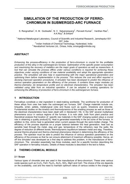
Ferro<strong>chromium</strong> ProductionSIMULATION OF THE PRODUCTION OF FERRO-CHROMIUM IN SUBMERGED-ARC FURNACES. Rangnathan 1 , K. M. Godiwalla 1 , N. V. Satyanarayana 2 , Parvesh Kumar 1 , Vardhan Rao 3 ,A.K.Roy 3 , B.Srikant 31 National Metallurgical Laboratory, Council of Scientific and Industrial Rese<strong>arc</strong>h, Jamshepdur 831007, India2Indian Institute of Chemical Technology, Hyderabad, India3 Navabahrat Ventures Ltd., Orissa, India, sriranga@nml<strong>in</strong>dia.orgABSTRACTEnhanc<strong>in</strong>g the process-efficiency <strong>in</strong> the production of ferro-<strong>chromium</strong> is crucial for the profitableproduction of this alloy <strong>in</strong> the <strong>submerged</strong>-<strong>arc</strong> <strong>furnace</strong>. Optimi<strong>za</strong>tion of the specific power <strong>co</strong>nsumptionand maximiz<strong>in</strong>g the re<strong>co</strong>very of metallics are the major goals of operators as well as rese<strong>arc</strong>hers. Atool that can simulate the process offl<strong>in</strong>e under various <strong>co</strong>nditions is required for achiev<strong>in</strong>g theseobjectives under vary<strong>in</strong>g <strong>co</strong>nditions of raw material availability and adopt the appropriate operationpractice. The simulation will also help <strong>in</strong> experiment<strong>in</strong>g with the major operational parameters andoptimis<strong>in</strong>g them before implementation <strong>in</strong> the process. This reduces the <strong>co</strong>st and effort required <strong>in</strong>devis<strong>in</strong>g improved operation procedures. A simulator has been developed to predict the <strong>in</strong>fluence ofvarious operation parameters on the efficiency of the process. It <strong>co</strong>nta<strong>in</strong>s three major modules (a)thermo-chemistry; (b) temperature profile and (c) electrical characteristics. The simulator has beenvalidated us<strong>in</strong>g data from an <strong>in</strong>dustrial operation. It can be adopted <strong>in</strong> exist<strong>in</strong>g operations forenhanc<strong>in</strong>g the efficiency of production of ferro-<strong>chromium</strong> <strong>in</strong> the <strong>submerged</strong>-<strong>arc</strong> <strong>furnace</strong>.1 INTRODUCTIONFerroalloys <strong>co</strong>nstitute a vital <strong>in</strong>gredient <strong>in</strong> steel-mak<strong>in</strong>g worldwide. The workhorse for production ofthese alloys from ores has been the <strong>submerged</strong> <strong>arc</strong> <strong>furnace</strong>, SAF. Charge materials <strong>in</strong>clude ore,briquette, s<strong>in</strong>ter, pellets, metallurgical <strong>co</strong>ke and fluxes such as quartz, limestone and dolomite.Fundamental studies on the k<strong>in</strong>etics and thermodynamics of the smelt<strong>in</strong>g process as well as those ofthe electrical characteristics have been dealt with <strong>in</strong> literature[1–16]. In the SAF several multiphasephenomena occur <strong>in</strong> various regions of the <strong>furnace</strong>. It is now clear, both from plant practice andtheoretical analysis that location of specific raw materials <strong>in</strong> the SAF charg<strong>in</strong>g system plays a crucialrole <strong>in</strong> obta<strong>in</strong><strong>in</strong>g a quality product[13]. Heat is generated essentially <strong>in</strong> the <strong>arc</strong>-zone of the <strong>furnace</strong>. Inaddition to this, ohmic heat is generated when current passes through the semi-molten charge. Theefficiency of the process depends on a proper balance between the heat generation, heat lost assensible heat through the metal, slag and gas; temperature of the refractory near the walls; thedegree of reduction at different levels; thermodynamic equilibrium between metal and slag. Therefore,several thermo-physical and thermo-chemical phenomena <strong>in</strong>teract <strong>in</strong> determ<strong>in</strong><strong>in</strong>g the efficiency of theprocess. The operator must be able to predict the <strong>in</strong>fluence of various operation parameters on theefficiency of the process so that he can ensure atta<strong>in</strong>ment of maximum efficiency possible. Hence, anoff l<strong>in</strong>e simulator was developed as a first step to address this problem, <strong>in</strong> the manufacture of ferro<strong>chromium</strong>.The simulator essentially has three modules, each for a specific function describ<strong>in</strong>g theSAF operation <strong>in</strong> ferroalloy <strong>in</strong>dustry. Details of these modules is described <strong>in</strong> the text to follow.2 THERMO-CHEMICAL MODULE2.1 S<strong>co</strong>peVarious types of chromite ores are used <strong>in</strong> the manufacture of ferro-<strong>chromium</strong>. These ores variousoxide species such as Cr 2 O 3 , FeO, Fe 2 O 3 , Al 2 O 3 , SiO 2 , MgO and CaO. The choice of the ore dependson the availability, <strong>co</strong>st and the need to ma<strong>in</strong>ta<strong>in</strong> optimum ratios of various oxides <strong>in</strong> the charge mix.The Twelfth International Ferroalloys CongressSusta<strong>in</strong>able Future401June 6 – 9, 2010Hels<strong>in</strong>ki, F<strong>in</strong>land
Ferro<strong>chromium</strong> Production(c) Use the <strong>in</strong>formation on the size of the high temperature zone to regulate the operation. The sizeof this zone must be optimum. Higher the size, higher is the reduction of SiO 2 and higher is thespecific power <strong>co</strong>nsumption. If the size is less than the optimum, there will be improper distribution oftemperature lead<strong>in</strong>g to problems <strong>in</strong> operation as well reduced re<strong>co</strong>very of metallics.3. The ‘energy’ screen tells how the energy supplied to the <strong>furnace</strong> is utilized. This, <strong>in</strong> turn, will help <strong>in</strong>devis<strong>in</strong>g strategies to reduce the wasteful expenditure of energy. An important aspect of energy lossis the heat lost through the slag as sensible heat. This depends essentially on the liquidustemperature of the slag. Analysis of data from <strong>in</strong>dustry has shown that there is a huge variation <strong>in</strong> thistemperature lead<strong>in</strong>g to an enormous wastage of energy. This screen gives a reliable estimate of theliquidus temperature. Us<strong>in</strong>g this, the operator can f<strong>in</strong>e-tune the <strong>co</strong>mposition of the slag, so that theliquidus is <strong>co</strong>ntrolled with<strong>in</strong> a narrow limit. This will <strong>co</strong>nsiderably reduce the specific energy<strong>co</strong>nsumption. Heat loss through the gas is another source of loss which can be m<strong>in</strong>imized us<strong>in</strong>g thismodule. This can be achieved us<strong>in</strong>g the modules on ‘reduction k<strong>in</strong>etics’ and on the ‘temperatureprofile’, along with the ‘energy’ screen. Another important <strong>co</strong>ntribution by this module is help<strong>in</strong>g theoperator to schedule the tapp<strong>in</strong>g. When the operator is aware how much of energy is actually requiredper tonne of hot metal, he can schedule the tapp<strong>in</strong>g with good precision, lead<strong>in</strong>g to <strong>co</strong>nsiderablesav<strong>in</strong>g <strong>in</strong> energy. A screen shot of the ‘energy’ screen is given <strong>in</strong> fig. 1.4. The module on the ‘reduction k<strong>in</strong>etics’ will be useful for the operator to estimate the total timerequired for reduction reactions to be <strong>co</strong>mpleted and optimally schedule the tapp<strong>in</strong>g of metal basedon this <strong>in</strong>formation. This can avoid premature tapp<strong>in</strong>g lead<strong>in</strong>g to losses <strong>in</strong> slags or over-heat<strong>in</strong>g of themetal which will dra<strong>in</strong> energy without proportionate <strong>in</strong>crease <strong>in</strong> production.Figure 1:The “Energy” screen of the Simulator.The Twelfth International Ferroalloys CongressSusta<strong>in</strong>able Future403June 6 – 9, 2010Hels<strong>in</strong>ki, F<strong>in</strong>land
Ferro<strong>chromium</strong> Production3 TEMPERATURE PROFILE MODEL AND SIMULATION3.1 S<strong>co</strong>peOptimum temperature profile of the <strong>furnace</strong> is crucial for the successful operation of the process.Temperatures at the hearth and tap hole region must be above the liquidus temperature of the metaland that of the slag so that these liquids do not freeze and tapp<strong>in</strong>g is smooth. The temperaturedistribution must be symmetric <strong>in</strong> the <strong>furnace</strong> along the radial direction. The top of the charge bedmust be at an optimum temperature so that the heat loss through radiation and <strong>co</strong>nvection ism<strong>in</strong>imized. The heat carried away by the top gas also should be m<strong>in</strong>imum. The temperaturedistribution must be such that the charge gets adequate time to get reduced as it travels down the<strong>furnace</strong> to the hearth region. This will have an impact on the schedul<strong>in</strong>g of metal tapp<strong>in</strong>g formaximis<strong>in</strong>g efficiency of operation. The ‘Temperature Profile’ Module must be capable of provid<strong>in</strong>g thefollow<strong>in</strong>g crucial <strong>in</strong>formation: (1) Temperature of the metal and slag at the hearth level: (2)Temperature at the slag port; (3) Size of the high temperature zone: (4) Sizes of various temperaturezones: (5) Temperature at the op of the charge bed: (6) Temperature along the walls3.2 Factors Influenc<strong>in</strong>g the Temperature ProfileThe follow<strong>in</strong>g factors <strong>in</strong>fluence the temperature profile <strong>in</strong>side the <strong>furnace</strong>:1. Heat generation through ohmic heat<strong>in</strong>g <strong>in</strong> the various zones2. Temperature at the electrodes3. Heat capacities of charge materials, metal, slag.4. Thermal <strong>co</strong>nductivity of charge materials5. Heat requirement for reduction reactions and melt<strong>in</strong>g6. Porosity of the bed which is <strong>in</strong>fluenced by the particle size, shape etc.7. Quantity of gas generated and its heat capacity8. Thermal <strong>co</strong>nductivity of refractory9. Heat loss through radiation at the top of the charge bedThe modell<strong>in</strong>g of the temperature profile <strong>in</strong> the <strong>submerged</strong>-<strong>arc</strong> <strong>furnace</strong> has been already discussed <strong>in</strong>detail elsewhere[14]3.3 Us<strong>in</strong>g the Module <strong>in</strong> Industrial OperationThis module is a highly valuable tool for understand<strong>in</strong>g the operation and <strong>co</strong>ntroll<strong>in</strong>g it.1. Comb<strong>in</strong>ed with the module on ‘reduction k<strong>in</strong>etics’, this module will give an estimate ofthe time required for the <strong>co</strong>mplete reduction of <strong>chromium</strong> and iron. This can be used forschedul<strong>in</strong>g the tapp<strong>in</strong>g of metal and slag.2. The module can be used for adjust<strong>in</strong>g factors such as bed porosity to generate an idealtemperature profile that can m<strong>in</strong>imise the heat loss through the walls.3. This module will give an estimate of the high temperature zone. This can be <strong>co</strong>ntrolledthrough appropriate modification <strong>in</strong> operation practice, such as applied voltage, chargedistribution on the top of the bed etc.4. This module will serve to explore the <strong>in</strong>fluence of altered charge distribution on the top ofthe bed and develop new operation practices.5. This module can be used for <strong>co</strong>ntroll<strong>in</strong>g the temperature of the top gas and reduce theloss through this.Figure 2 gives a typical temperature profile <strong>in</strong> a <strong>submerged</strong>-<strong>arc</strong> <strong>furnace</strong>.The Twelfth International Ferroalloys CongressSusta<strong>in</strong>able Future404June 6 – 9, 2010Hels<strong>in</strong>ki, F<strong>in</strong>land
Ferro<strong>chromium</strong> ProductionFigure 2:Predicted Temperature profile <strong>in</strong> the Submerged-Arc Furnace.4 SIMULATION OF ELECTRICAL CHARACTERISTICS4.1 S<strong>co</strong>peThe data available from the <strong>furnace</strong> operation on the electrical parameters are the primary voltage ofthe transformer, the primary current and transformer ratio. From these, the other relevant parametershave to be estimated. This module can provide: (1) Estimated se<strong>co</strong>ndary voltage across eachelectrode: (2) Estimated se<strong>co</strong>ndary current through each electrode; (3) Resistance of the <strong>arc</strong> medium;(4) Current density below each electrode; (5) Power density below each electrode; (6) Monitor<strong>in</strong>g ofelectrical parameters at <strong>in</strong>tervals of ten m<strong>in</strong>utes; (7) Monitor<strong>in</strong>g of the data every hour4.2 Process RequirementsThe power distribution through the three electrodes must be uniform for ideal operation. The powerdistribution and current distribution along the axial and radial directions must be such that thesedistributions are uniform and are at the optimum level for maximum efficiency of operation. Nonuniformdistribution will lead to uneven charge descent; excessive erosion of refractory <strong>in</strong> someregions; accumulation of un-reacted material <strong>in</strong> some regions; <strong>in</strong>efficient utilisation of <strong>furnace</strong> volume;excessive erosion of electrode(s). Monitor<strong>in</strong>g of <strong>arc</strong> resistance is vital for <strong>co</strong>ntroll<strong>in</strong>g the process.Ideally, the resistance must be ma<strong>in</strong>ta<strong>in</strong>ed <strong>co</strong>nstant throughout the operation, after allow<strong>in</strong>g forchanges dur<strong>in</strong>g tapp<strong>in</strong>g of metal and subsequent build-up of charge under the electrodes. Modell<strong>in</strong>gthe electrical characteristics are discussed <strong>in</strong> detail elsewhere[17].The Twelfth International Ferroalloys CongressSusta<strong>in</strong>able Future405June 6 – 9, 2010Hels<strong>in</strong>ki, F<strong>in</strong>land
Ferro<strong>chromium</strong> Production4.3 Determ<strong>in</strong>ation of Current-density and Power-density ProfilesThe SAF typically operates <strong>in</strong> the current range 1.5 to 4.7 A/cm 2. The operation characteristics of theprocess depends on the resistance. The resistance depends on <strong>arc</strong><strong>in</strong>g, carbon balance and theelectrode-to-bath distance. These factors must be <strong>co</strong>ntrolled <strong>in</strong> the operation of SAF. Consistent withthe restrictions on the distribution of power with<strong>in</strong> a <strong>furnace</strong> and the limitations on electroderesistance, factors such as <strong>in</strong>ter electrode spac<strong>in</strong>g, <strong>furnace</strong> <strong>in</strong>ternal diameter and depth can becalculated. From a knowledge of the se<strong>co</strong>ndary voltage and current, the current density and powerdensity under the electrodes are predicted.4.4 Us<strong>in</strong>g the Module <strong>in</strong> Industrial OperationThe module can be used <strong>in</strong> <strong>co</strong>ntroll<strong>in</strong>g the operation through the follow<strong>in</strong>g strategies:1. Monitor<strong>in</strong>g the se<strong>co</strong>ndary current and voltage at short time <strong>in</strong>tervals and tak<strong>in</strong>g <strong>co</strong>rrective action toma<strong>in</strong>ta<strong>in</strong> balance of power supply among the three electrodes.2. Ma<strong>in</strong>ta<strong>in</strong><strong>in</strong>g appropriate se<strong>co</strong>ndary voltage and current among the electrodes3. Ma<strong>in</strong>ta<strong>in</strong><strong>in</strong>g the optimum <strong>arc</strong>-resistance4. Ma<strong>in</strong>ta<strong>in</strong><strong>in</strong>g the optimum power density and current density profiles.Figures 3 and 4 represent the current and power densities estimated for an <strong>in</strong>dustrial <strong>furnace</strong>.Figure 3:The Current Density profile of a Submerged-Arc Furnace Around the Electrodes.The Twelfth International Ferroalloys CongressSusta<strong>in</strong>able Future406June 6 – 9, 2010Hels<strong>in</strong>ki, F<strong>in</strong>land
Ferro<strong>chromium</strong> ProductionFigure 4:The Power Density Profile of a Submerged-Arc Furnace Around the Electrodes.5 VALIDATIONData were <strong>co</strong>llected from <strong>in</strong>dustries to validate the simulator. Figure 5 <strong>co</strong>mpares the quantity of metalproduced predicted by the simulator with that reported by the Plant. Though there is scatter <strong>in</strong> eitherdirection, the two sets of data agree with each other with an average deviation of 1.65%. Similaragreement is seen between the sets of data with respect to the <strong>co</strong>mposition of the slag as well as theheat required for the process as demonstrated <strong>in</strong> figures 6 and 7. Consider<strong>in</strong>g the <strong>co</strong>nsiderabledifficulty <strong>in</strong> generat<strong>in</strong>g dat with high accuracy <strong>in</strong> <strong>in</strong>dustrial operation, the agreement between thevalues predicted by the simulator and the data reported by the plant is <strong>co</strong>nsidered to be excellent.The Twelfth International Ferroalloys CongressSusta<strong>in</strong>able Future407June 6 – 9, 2010Hels<strong>in</strong>ki, F<strong>in</strong>land
Ferro<strong>chromium</strong> ProductionPredicted Production vs reported Data, Plant A165Reported Data, TPD155Av. Deviation = 1.65%145145 155 165Predicted production, TPDFigure 5:Predicted production <strong>co</strong>mpared with Plant data.Predicted %SiO2 vs Reported Data, Plant A35Reported Data, wt%SiO233312927Av. Deviation = - 0.2079 units2525 27 29 31 33 35Predicted SiO2, w t%SiO2Figure 6:Predicted slag <strong>co</strong>mposition <strong>co</strong>mpared with Plant data.The Twelfth International Ferroalloys CongressSusta<strong>in</strong>able Future408June 6 – 9, 2010Hels<strong>in</strong>ki, F<strong>in</strong>land
Ferro<strong>chromium</strong> ProductionPreicted Heat vs Reported Heat, Plant A600Reported Heat for Production, MWh550500500 550 600Predicted Heat for Production, MWhFigure 7:Predicted heat requirement <strong>co</strong>mpared with plant data.6 SUMMARYA simulator has been developed for predict<strong>in</strong>g the performance of the process dur<strong>in</strong>g the productionof ferro-<strong>chromium</strong> <strong>in</strong> <strong>submerged</strong>-<strong>arc</strong> <strong>furnace</strong> under various operation <strong>co</strong>nditions. The simulatorpredicts the thermo-chemistry, the temperature profile and the electrical characteristics of the process.This can be used for enhanc<strong>in</strong>g the efficiency of the process by maximis<strong>in</strong>g the re<strong>co</strong>very of metallicsand optimis<strong>in</strong>g the energy <strong>co</strong>nsumption. The various features of the simulator and its application <strong>in</strong><strong>in</strong>dustrial environment have been discussed. The modules have been named FERALSIM1,FERALSIM2 AND FERALSIM3. These are available for use by the <strong>in</strong>dustries to enhance theefficiency of their processes.7 ACKNOWLEDGEMENTThe authors are grateful to the Department of Information Technology, M<strong>in</strong>istry of Communication andInformation technology for f<strong>in</strong>ancial support to carry out the <strong>in</strong>vestigations presented above.8 REFERENCES[1] J.Yonemochi, Innovations and Improvements <strong>in</strong> Metallurgical Processes – Ferro alloys -I, ElectricFurnace Conference Proceed<strong>in</strong>gs, 1976, pp.73-84.[2] M.S.Rennie, MINTEK ’50, Ed. L.F. Houghton, 2(1985), pp.777-785.[3] J.Westly, Electric, Furnace Conference Proceed<strong>in</strong>gs, 1975, pp.47-53[4] J.H. Down<strong>in</strong>g and F.W.Leavitt, INFACON ’80, Se<strong>co</strong>nd International Ferro Alloy Congress,Lusanne, Switzerland, 12-16 Oct. 1980, Institut des Producteurs de Ferro- Alliages d’EuropeOccidentale, 20 ave. de la Gare, pp.83-107.[5] G.Sommer, N.A. B<strong>arc</strong><strong>za</strong>, I.J.Baker, M.S.Rennie, A.B.Stewart, INFACON ’80, Se<strong>co</strong>nd InternationalFerro Alloy Congress, Lusanne, Switzerland, 12-16 Oct. 1980, Institut des Producteurs deFerro-Alliages d’Europe Occidentale, 20 ave. de la Gare, pp.53-70[6] B.O’Shoughassey and M.Sciaronne, INFACON ’80, Se<strong>co</strong>nd International Ferro Alloy Congress,Lusanne, Switzerland, 12-16 Oct. 1980, Institut des Producteurs de Ferro-Alliages d’EuropeOccidentale, 20 ave. de la Gare, pp.370-385.[7] J.H.Down<strong>in</strong>g and F.W.Leavitt, 36 th Elec. Furnace Conf. Proceed., 1978, pp.209-216.The Twelfth International Ferroalloys CongressSusta<strong>in</strong>able Future409June 6 – 9, 2010Hels<strong>in</strong>ki, F<strong>in</strong>land
Ferro<strong>chromium</strong> Production[8] S.Xu and W.Dai, INFACON 6, Proceed. 6 th Intl. Ferro alloy Congress, Cape Town, Johannesburg,South African Institute of M<strong>in</strong><strong>in</strong>g and Metallurgy, 1992, pp.87-92.[9] D. Neuschutz, INFACON 6, Proceed. 6 th Intl. Ferro alloy Congress, Cape Town, Johannesburg,South African Institute of M<strong>in</strong><strong>in</strong>g and Metallurgy, 1992, pp.65-70.[10] H.G.Va<strong>za</strong>rlis and A.Lekatou, Ironmak<strong>in</strong>g and Steelmak<strong>in</strong>g, 20(1993) 1, pp.42-53.[11] A.Lekatou and R.D.walker, Ironmak<strong>in</strong>g and Steelmak<strong>in</strong>g,22(1995) 5, pp.378-392.[12] Y.L.D<strong>in</strong>g and N.A.Warner, Ironmak<strong>in</strong>g and Steelmak<strong>in</strong>g, 24(1997) 3, pp.224-229.[13] S.Ranganathan, Ironmak<strong>in</strong>g and Stelmak<strong>in</strong>g,25(1998) 6, pp.466-471.[14] S.Ranganathan and K.M. Godiwalla, Steel rese<strong>arc</strong>h, 69(1998) 12, pp.476-481.[15] George W. Healy, Electric Furnace Conference Proceed<strong>in</strong>gs, 1991, pp.251-258[16] W.D.Heiss, “Modell<strong>in</strong>g and simulation of electric smelt<strong>in</strong>g <strong>furnace</strong>s”, Iron mak<strong>in</strong>g andSteelmak<strong>in</strong>g, 9(1982) 5, pp.217- 221[17] ‘Process Simulation for Optimisation of Ferro-Chrome Production <strong>in</strong> Submerged-Arc Furnace’,Internal Report, national Metallurgical laboratory, Jamshedpur, India.The Twelfth International Ferroalloys CongressSusta<strong>in</strong>able Future410June 6 – 9, 2010Hels<strong>in</strong>ki, F<strong>in</strong>land


