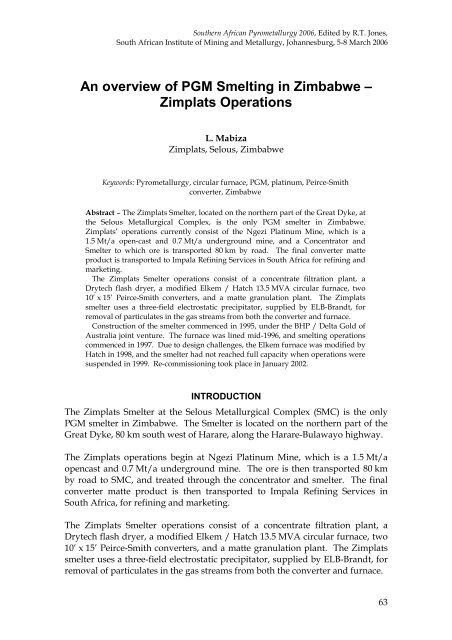
An overview of PGM Smelting in Zimbabwe – Zimplats ... - saimm
An overview of PGM Smelting in Zimbabwe – Zimplats ... - saimm
An overview of PGM Smelting in Zimbabwe – Zimplats ... - saimm
You also want an ePaper? Increase the reach of your titles
YUMPU automatically turns print PDFs into web optimized ePapers that Google loves.
Construction <strong>of</strong> the Smelter commenced <strong>in</strong> 1995, under the BHP / Delta Gold <strong>of</strong>Australia jo<strong>in</strong>t venture. The furnace was l<strong>in</strong>ed mid-1996, and smelt<strong>in</strong>goperations commenced <strong>in</strong> 1997. Due to design challenges, the Elkem furnacewas modified by Hatch <strong>in</strong> 1998, and the smelter had not reached full capacitywhen operations were suspended <strong>in</strong> 1999.Each <strong>of</strong> the unit operations <strong>of</strong> the smelter is described <strong>in</strong> greater detail below.Figure 1 shows how concentrate is handled at the smelter.Figure 1: Concentrate handl<strong>in</strong>g at <strong>Zimplats</strong> Smelter64FILTRATION PLANTThickened concentrate (45% solids) is pumped from the thickener <strong>in</strong>to one <strong>of</strong>the two receiv<strong>in</strong>g tanks equipped with agitators. The tanks are mounted onload cells, for metallurgical account<strong>in</strong>g purposes, and each full tank receipt istreated as a batch. Concentrate from receiv<strong>in</strong>g tanks is then pumped to anagitated storage tank.Dur<strong>in</strong>g the BHP operation up to November 2002, the concentrate was be<strong>in</strong>gfiltered <strong>in</strong> two horizontal pressure presses (Perr<strong>in</strong> Presses).The filter presses were designed for a comb<strong>in</strong>ed output <strong>of</strong> 17 metric tons perhour (dry), at 85% runn<strong>in</strong>g time. The design figure for product moisturecontent was 14%, and the two presses were designed to operate <strong>in</strong> parallel, withone press be<strong>in</strong>g filled whilst the other press was be<strong>in</strong>g pressed and cleaned.The two filter presses operated at 110 tons per day per press, at 24% cake
& 2005 91-3 & -7-Eleven, Inc.& 7
• Storage silos (150 t and 350 t) for dried concentrate, and pneumatic feedsystem to the furnaceWet concentrate cake from the filter press is dropped <strong>in</strong>to a reclaim hopperthrough the double screw feeders onto a dryer feed conveyor.The concentrate cake is then discharged <strong>in</strong>to a heavy-duty back-mixer. A driedconcentrate recycle stream is mixed with wet filter cake <strong>in</strong> the back-mixer (thispractice was stopped s<strong>in</strong>ce the Larox was commissioned). The wet concentrateis discharged from the back-mixer onto a cake dis<strong>in</strong>tegrator. The dis<strong>in</strong>tegratorserves the purpose <strong>of</strong> distribut<strong>in</strong>g feed evenly, and breaks concentrate furtherto feed <strong>in</strong>to the <strong>in</strong>com<strong>in</strong>g hot-gas air stream.The concentrate is conveyed up the dry<strong>in</strong>g column with a hot air stream, andconcentrate is dried on the way. Collection <strong>of</strong> dry concentrate is done through acyclone underflow. The cyclone overflow goes through a settl<strong>in</strong>g chamber ordryer heat-s<strong>in</strong>k box, then <strong>in</strong>to the dryer bag-house. The bag-house is a fabricfilter, jet-pulse type, with fabric material resistant to acids and moisture, andoperates at a temperature <strong>of</strong> 140ºC. The dryer product enters the bag-housethrough the <strong>in</strong>let at the bottom section <strong>of</strong> the bag-house, and rises upwardsthrough the bags. Ultra-f<strong>in</strong>e concentrate is trapped on the bags. Each row <strong>of</strong>bags <strong>in</strong> the module is pulsed down <strong>in</strong> rapid sequence to release the concentratef<strong>in</strong>es; this sequence is fully automated. <strong>An</strong> emergency air dilution valve hasbeen <strong>in</strong>stalled upstream <strong>of</strong> the bag-house to protect the fabric filter bags fromover-temperature conditions (opened on signal from a temperature switch).The released concentrates are dropped onto a screw conveyor to the concentratehold<strong>in</strong>g bus. Outlet moisture content <strong>of</strong> the dried concentrate has beenconsistently averag<strong>in</strong>g 0.2 – 0.3% (cf.
In general, the hot-gas generator operates directly coupled to the flash dryer,and their controls are <strong>in</strong>terl<strong>in</strong>ked, but a hot provision is available for runn<strong>in</strong>gthe hot-gas generator <strong>in</strong>dependently <strong>of</strong> the dryer.The advantages <strong>of</strong> us<strong>in</strong>g a flash dryer are the high energy efficiency and lowoperat<strong>in</strong>g costs; the only major disadvantage be<strong>in</strong>g the high capital cost.Figure 2 shows the overall smelter flowsheet. (<strong>An</strong> enlarged version appears atthe end <strong>of</strong> this paper.)Off-gasFIG 2 - <strong>Zimplats</strong> smelterOff-gasstackI.D fanCycloneBaghouse23-25% moistureWet ScrewFeeder30-45%RecycledFlash DryerDryer feed conveyorConcentratestorage shedOff-gasBack-mixerCoalHot gasgeneratorHatch-ElkemFurnaceConcentratefeed b<strong>in</strong>(Moisture < 0.5%)AirDis<strong>in</strong>tegratorOff-gasstackSlagElectrostaticPrecipitatorI.D. fanAsh classifiersDischargeFurnace matteLimestone/RevertsMatteGranulationTo concentratefeed b<strong>in</strong>Converter Slag RecycledPierce SmithConverterHigh grade mattefor SaleFigure 2: Smelter flowsheet at <strong>Zimplats</strong>FURNACEThe furnace is the ‘hub’ <strong>of</strong> the smelter operation. The circular (12 m shelldiameter) three-electrode submerged-arc Elkem furnace is rated at 13.5 MVAwith a power density <strong>of</strong> 134 kW/m 2 at 12 MW. The furnace was orig<strong>in</strong>ally<strong>in</strong>stalled <strong>in</strong> 1996, but experienced problems <strong>of</strong> severe sidewall refractoryerosion dur<strong>in</strong>g its operation <strong>in</strong> 1997 and part <strong>of</strong> 1998.In 1998, Hatch was commissioned to redesign the furnace, and severalimprovements were made to the furnace, which <strong>in</strong>cluded:• Water-cooled copper cool<strong>in</strong>g elements <strong>in</strong> the slag zone• Air-cooled copper cool<strong>in</strong>g f<strong>in</strong>s at the matte level• Water-cooled copper tap blocks / tapholes• B<strong>in</strong>d<strong>in</strong>g system, provid<strong>in</strong>g vertical refractory compression67
68• Electrode seals• New feed-pipe arrangement <strong>in</strong>to furnaceThe orig<strong>in</strong>al furnace was l<strong>in</strong>ed with mag-chrome refractory bricks. Sidewallcool<strong>in</strong>g was ma<strong>in</strong>ly by natural convection and radiation to the surround<strong>in</strong>g air.The furnace suffered severe slag zone erosion, and a run-out occurred soonafter start up <strong>in</strong> 1997. After the run-out, BHP repaired the sidewall withcastable refractory, and <strong>in</strong>stalled a spray cool<strong>in</strong>g system on the outside <strong>of</strong> theshell. To improve energy transfer through the refractory wall, the refractorywas anchored by copper bars protrud<strong>in</strong>g through the shell plate to the cool<strong>in</strong>gwater. Operation <strong>of</strong> the furnace resumed with this configuration forapproximately one year, but this design could not susta<strong>in</strong> operations at powerlevels higher than 7 MW.The refractory cool<strong>in</strong>g solution selected for a particular application depends onthe energy flux expected from that process. The measurements on the <strong>Zimplats</strong>furnace <strong>in</strong> comparison to other Cu-Ni-<strong>PGM</strong> furnace energy fluxes <strong>of</strong> 15-20 kW/m 2 were expected, but an energy flux <strong>of</strong> 75 kW/m 2 was adopted fordesign purposes, to cater for process excursions known to produce energyfluxes <strong>of</strong> about twice the average value under normal operation.Work commenced <strong>in</strong> August, and the retr<strong>of</strong>itted furnace was restarted <strong>in</strong>October 1998.Furnace design featuresThe <strong>Zimplats</strong> furnace is a 13.5 MVA, three-electrode circular furnace with thefollow<strong>in</strong>g dimensions:• Diameter at <strong>in</strong>side <strong>of</strong> shell plate = 12 000 mm• Diameter at <strong>in</strong>side <strong>of</strong> refractory l<strong>in</strong><strong>in</strong>g (as built, no wear) = 11 100 mm• The furnace has two matte tapholes at the south end <strong>of</strong> the furnace, andtwo slag tapholes at the north end <strong>of</strong> furnaceGeneral operat<strong>in</strong>g conditions:• Free-board temperatures average 250ºC, with excursions to 500ºC• Matte temperature averages 1330ºC, with excursions to 1400ºC• Slag temperatures average 1560ºC, with excursions to 1600ºC• Matte tapp<strong>in</strong>g frequency is 60 tons every 48 hours• Slag tapp<strong>in</strong>g is semi-cont<strong>in</strong>uous; slag tapholes are open 75% <strong>of</strong> the time,and the slag is immediately granulated and disposed <strong>of</strong>The furnace is essentially a slag producer, with matte be<strong>in</strong>g a ‘by-product’. Atotal molten bath <strong>of</strong> 1 700 mm is ma<strong>in</strong>ta<strong>in</strong>ed <strong>in</strong> the furnace. Furnace sound<strong>in</strong>gis a critical activity on the furnace, and hourly sound<strong>in</strong>g measurements arecarried out with the <strong>in</strong>volvement <strong>of</strong> senior personnel on shift. The concentratecharg<strong>in</strong>g rate is determ<strong>in</strong>ed by the power <strong>in</strong>put, target<strong>in</strong>g an efficiency ratio <strong>of</strong>900 kWh/t <strong>of</strong> concentrate smelted. A black top is ma<strong>in</strong>ta<strong>in</strong>ed <strong>in</strong> the furnace.Furnace matte tapp<strong>in</strong>g is carried out every 48 hours.
Furnace electrode construction is the modular Elkem type; the electrodes areessentially carbon, the self-bak<strong>in</strong>g Söderberg type. Electrode bak<strong>in</strong>g isenhanced by electrode heaters <strong>in</strong>stalled along the electrode column above theelectrode contact pads.The control room operator has a key role <strong>in</strong> coord<strong>in</strong>at<strong>in</strong>g activities around thefurnace and the smelter plant as a whole (from concentrate receiv<strong>in</strong>g to f<strong>in</strong>alconverter matte handl<strong>in</strong>g). The whole plant is run us<strong>in</strong>g a SCADA system, andthe control room operator monitors the plant through this system and thenliaises with field personnel.Furnace technical aspectsTable I: Furnace parametersFurnace Transformer Rat<strong>in</strong>g (MVA) 13.5Primary voltage (V) 11 000Full furnace load (MW) 12Secondary Current (kA) 25-27Electrode resistance (mΩ) 5-7Radius at the <strong>in</strong>side <strong>of</strong> the shell plate (mm) 6000Radius at the <strong>in</strong>side <strong>of</strong> the refractory l<strong>in</strong><strong>in</strong>g (no wear) (mm) 5550Refractory upper sidewall (mm) 450Refractory lower side wall (mm) 550Average Freeboard temperature ( o C) 250Specific Power Consumption (kWh/t <strong>of</strong> concentrates) 900Ingress air (Nm 3 /h) 14 000Electrode diameter (mm) 1200Electrode Cas<strong>in</strong>g length (mm) 2000Electrode cas<strong>in</strong>g thickness (mm) 2Number <strong>of</strong> contact clamps 6Current density – Cas<strong>in</strong>g (A/mm 2 ) 3.79Current density – Cas<strong>in</strong>g and f<strong>in</strong>s (A/mm 2 ) 1.75Furnace reactionsThe ma<strong>in</strong> reaction that take place dur<strong>in</strong>g smelt<strong>in</strong>g are considered to be:3(FeS)2.NiS + O2 = Ni3S2 + 6FeS + SO22CuFeS2 + O2 = Cu2S + SO2 + FeSFe7S8 + O2 = 7FeS + SO23(Fe3O4) + FeS = 10(FeO) + SO269
9(NiO) + 7FeS = 3Ni3S2 + 7FeO + SO2The compounds Ni3S2, Cu2S, FeS, and m<strong>in</strong>or levels <strong>of</strong> cobalt make up furnacematte, together with <strong>PGM</strong>s and other precious metals (gold) which do notparticipate <strong>in</strong> furnace chemical reactions.Slag formation is basically considered to be:2(FeO) + SiO2 = 2FeO.SiO2Other oxides <strong>in</strong> the concentrate (Al2O3, MgO, etc.) report to the slag.Furnace <strong>of</strong>f-gasNo fuel is burnt <strong>in</strong> the furnace, hence the volume <strong>of</strong> waste gas and the quantity<strong>of</strong> flue dust is small. The <strong>of</strong>f-gas conta<strong>in</strong>s ma<strong>in</strong>ly sulphur oxides, and carbonoxides (from electrodes). The <strong>of</strong>f-gas is sucked to the electrostatic precipitator.Modifications carried out on the furnace s<strong>in</strong>ce <strong>Zimplats</strong> took over theoperations• The slag / concentrate <strong>in</strong>terface brickwork (9 courses) was observed tobe severely hydrated. The n<strong>in</strong>e rows <strong>of</strong> bricks were replaced with somemag-chrome bricks, and <strong>in</strong>spections to date show that the brickwork isstill <strong>in</strong> good condition.• Dur<strong>in</strong>g the process <strong>of</strong> replac<strong>in</strong>g the n<strong>in</strong>e courses <strong>of</strong> mag-chromebrickwork, the furnace walls were taken down from the top to the lowestcourse to be replaced. This was made possible after lift<strong>in</strong>g the furnacero<strong>of</strong> and hold<strong>in</strong>g it <strong>in</strong> a position that enabled removal <strong>of</strong> the bricks. Ro<strong>of</strong><strong>in</strong>tegrity was ma<strong>in</strong>ta<strong>in</strong>ed by lift<strong>in</strong>g (jack<strong>in</strong>g) the r<strong>in</strong>g beam evenly.• Feed from the electrostatic precipitator was previously routed back to thedryer b<strong>in</strong>s. This was re-routed to feed the furnace.• There was a move away from pneumatically feed<strong>in</strong>g reverts back <strong>in</strong>tothe furnace, to the use <strong>of</strong> a simpler manual mechanical system.• The whole furnace cool<strong>in</strong>g circuit was renewed, and the pipe renewalwas done with the furnace on l<strong>in</strong>e <strong>in</strong> 2003.• The matte taphole copper blocks were modified on the bottom section(cold face); the cool<strong>in</strong>g pipe was withdrawn and the cold face front waswaffled to enable refractory pack<strong>in</strong>g. This design would prevent thecopper block from be<strong>in</strong>g cut by molten matte <strong>in</strong> the case <strong>of</strong> a matte runoutthrough the taphole or a face-plate failure.• There has been a move away from water-cooled cooper face-plate to caststeel face-plate.CONVERTERS<strong>Zimplats</strong> has two 10’ x 15’ Peirce-Smith converters with 22 tuyeres (18 <strong>in</strong> use),which are utilised to produce converter matte <strong>of</strong> 0.6% Fe from furnace matteconta<strong>in</strong><strong>in</strong>g 42% Fe and 31% S. The converters are operated <strong>in</strong> a batch cycle(every 48 hours) and only one converter is operated at a time.70
Operational practiceThe furnace matte is charged, and, dur<strong>in</strong>g blow<strong>in</strong>g, silica/quartz sized at 5-15 mm is charged at regular <strong>in</strong>tervals. Ladle dregs/reverts are charged <strong>in</strong>to theconverter at regular <strong>in</strong>tervals to control the temperature <strong>of</strong> the converter, andalso to boost production from ladle clean<strong>in</strong>gs. Silica is charged through feedpipes to flux the FeO, and the converter slag is skimmed at regular <strong>in</strong>tervals.The converter slag is returned to the furnace. Typical operat<strong>in</strong>g temperatureranges between 1100ºC and 1250ºC, and temperature monitor<strong>in</strong>g is through as<strong>in</strong>gle hood-mounted optical pyrometer per converter. Blower air, averag<strong>in</strong>g8 500 Nm 3 /h at 128 kPa, is blown <strong>in</strong>to the converter through the tuyeres. Localcontrol <strong>of</strong> the converter is by means <strong>of</strong> a SCADA system.The ma<strong>in</strong> reactions <strong>in</strong> the convert<strong>in</strong>g stage are oxidation <strong>of</strong> iron (II) sulphide,and slagg<strong>in</strong>g <strong>of</strong> iron (II) oxide by added silica/quartz flux.2FeS + 3O2 = 2FeO + 2SO2 (melt<strong>in</strong>g po<strong>in</strong>t <strong>of</strong> FeO is 1385 º C)2FeO + SiO2 = Fe2SiO4Formation <strong>of</strong> magnetite occurs near the tuyeres:3FeS + 5O2 = Fe3O4 + 3SO2 (melt<strong>in</strong>g po<strong>in</strong>t <strong>of</strong> Fe3O4 is 1597 º C)Oxygen reacts exothermically with iron sulphide, and hence supplies energy forthe converter. The temperature <strong>in</strong> the converter is controlled through theaddition <strong>of</strong> silica and cold reverts. There is no oxygen enrichment <strong>in</strong> theconverter process at <strong>Zimplats</strong>. Converter operations are complete at iron levels<strong>of</strong> 0.6 – 0.7% Fe.Converter tuyeres are kept clear <strong>of</strong> solid build-up by utilis<strong>in</strong>g a mechanicaltuyere puncher. The tuyere puncher is a rail-mounted carriage on which adouble-act<strong>in</strong>g air cyl<strong>in</strong>der is <strong>in</strong>stalled. The cyl<strong>in</strong>der drives up to three punchbars <strong>in</strong>to the tuyeres by means <strong>of</strong> guided yokes. The carriage moves along thetuyere l<strong>in</strong>e to punch successive tuyeres. The punch<strong>in</strong>g mach<strong>in</strong>e design alsomakes provision for mount<strong>in</strong>g a drill for drill<strong>in</strong>g the tuyere l<strong>in</strong>e <strong>of</strong> a newlyrel<strong>in</strong>ed converter.At the end <strong>of</strong> each batch cycle, after skimm<strong>in</strong>g <strong>of</strong> all the slag, the convertermatte is poured <strong>in</strong>to a converter matte ladle. The converter matte is taken formatte granulation at the matte granulation platform. The matte is then pouredonto a refractory-l<strong>in</strong>ed granulation spoon rest<strong>in</strong>g on a hydraulic platform. Thespoon <strong>in</strong>cludes a refractory bridge just ahead <strong>of</strong> the pour<strong>in</strong>g lip, designed tohold back any contam<strong>in</strong>at<strong>in</strong>g converter slag <strong>in</strong> the matte. Converter matte isdischarged over the spoon lip <strong>in</strong>to a f<strong>in</strong>ely distributed stream <strong>of</strong> granulationwater. The granulated matte discharges directly <strong>in</strong>to a steep-sided conicalbottomedtank.71
The orig<strong>in</strong>al granulated matte pump<strong>in</strong>g and dewater<strong>in</strong>g system was removed<strong>in</strong> 2002, and replaced with shaft-less screw conveyors from the bottom <strong>of</strong> thegranulation tank. The system dewaters matte to moisture levels averag<strong>in</strong>g 4%.The matte is then dried and exported to Impala Ref<strong>in</strong><strong>in</strong>g Services (IRS).The operat<strong>in</strong>g parameters for the converters are listed <strong>in</strong> Table II.Table II: Converter operat<strong>in</strong>g parametersParameter Units ConverterDiameter x Length ft 10 x 15Operat<strong>in</strong>g Total Charge / (ladles) 5Product Output / (White matte) t 16-18Number <strong>of</strong> tuyeres 18Tuyere length mm 1200Tuyere diameter mm 50Blow<strong>in</strong>g temperatures °C 1220-1250Air Flowrate Nm³h -1 8 500Air Pressure kPa 128Blow<strong>in</strong>g Cycle Time m<strong>in</strong>utes 600-720Granulation Time m<strong>in</strong>utes 50-60Silica used per blow t 18-22Matte treated per blow t 5672ELECTROSTATIC PRECIPITATORThe two major sources <strong>of</strong> <strong>of</strong>f-gas are the 13.5 MVA furnace and the two 10’ x 15’Peirce-Smith Converters. Off-gas from these two ma<strong>in</strong> sources is comb<strong>in</strong>ed andsent through the Electrostatic Precipitator before eventually be<strong>in</strong>g vented to theatmosphere.The furnace operation is such that seal<strong>in</strong>g <strong>of</strong> the furnace creates and ma<strong>in</strong>ta<strong>in</strong>s anegative pressure, at a gas temperature <strong>of</strong> approximately 425ºC and amaximum draft <strong>of</strong> 4 Nm 3 /s measured over 24 hours. Instantaneous peak flowsare such that dust load<strong>in</strong>g is approximately 3 468 kg/h at a dust concentration<strong>of</strong> 241 g/Nm 3 . <strong>An</strong> emergency stack is <strong>in</strong>stalled which can be used to isolate theduct<strong>in</strong>g system downstream. A pneumatically actuated damper is <strong>in</strong>stalled forthis. At the front end <strong>of</strong> the furnace, two matte tapp<strong>in</strong>g hoods above each <strong>of</strong> thetapholes are provided to m<strong>in</strong>imize sulphur dioxide emissions whilst tapp<strong>in</strong>gmatte. The two ducts are routed to jo<strong>in</strong> up with the ma<strong>in</strong> furnace <strong>of</strong>f-gas duct.Converter <strong>of</strong>f-gases are collected <strong>in</strong> air-cooled hoods that cover the convertermouth when the converter is <strong>in</strong> the blow<strong>in</strong>g position. Dilution air drawn <strong>in</strong>through the gap between the hood and the converter reduces the <strong>of</strong>f-gastemperature to less than 500ºC (represent<strong>in</strong>g a dilution <strong>in</strong> excess <strong>of</strong> 200% <strong>of</strong>
process blow<strong>in</strong>g gas). The gas handl<strong>in</strong>g system is based on an <strong>in</strong>stantaneouspeak flow, with a maximum temperature <strong>of</strong> 450ºC, gas flow <strong>of</strong> 9.8 Nm 3 /s, dustload<strong>in</strong>g <strong>of</strong> 240 kg/h, and a dust concentration <strong>of</strong> 6.8 g/Nm 3 . At the apex <strong>of</strong> theconverter hood is a gas distribution box where gas flow is either to theconverter <strong>of</strong>f-gas duct or to the emergency stack.The furnace and converter <strong>of</strong>f-gas are routed to enter a mix<strong>in</strong>g chamber justahead <strong>of</strong> a three-field electrostatic precipitator. The mix<strong>in</strong>g chamber effectivelymixes converter and furnace <strong>of</strong>f-gases before they enter the ESP. A mix<strong>in</strong>gchamber dilution damper modulates the flow to bleed <strong>in</strong> cold air to control theprecipitator <strong>in</strong>let temperature to 350ºC. In the precipitator, there are 15collector plates per electrode field; each collector plate is 11 m high and 3.5 mlong, provid<strong>in</strong>g a total collection surface area <strong>of</strong> 1 155 m 2 per electrostatic field.The precipitator is designed for the follow<strong>in</strong>g operat<strong>in</strong>g conditions - gas volume<strong>of</strong> 13.78 Nm 3 /s, operat<strong>in</strong>g temperature <strong>of</strong> 350ºC, <strong>in</strong>let dust <strong>of</strong> 64.3 g/Nm 3 , and aprecipitator <strong>in</strong>let pressure <strong>of</strong> 1.2 kPa. The precipitator has an outlet dustload<strong>in</strong>g <strong>of</strong> 50 mg/Nm 3 and a collection efficiency 99.9%. In 2003, a CO monitorwas <strong>in</strong>stalled follow<strong>in</strong>g an explosion <strong>in</strong> the precipitator. The explosion wassuspected to have been caused by coal, which was be<strong>in</strong>g used <strong>in</strong> the converters.CONCLUSIONThe <strong>Zimplats</strong> Smelter has undergone some design changes s<strong>in</strong>ce it wascommissioned <strong>in</strong> 1997: these be<strong>in</strong>g the Hatch modifications <strong>in</strong> 1998, and the<strong>Zimplats</strong> modifications from 2001 to 2005.The design between 1997 and 1998 has resulted <strong>in</strong> the furnace be<strong>in</strong>g called an‘Elkem/Hatch’ furnace. The period from January 2002 to the current time hasseen the furnace be<strong>in</strong>g run at full power (12.5 MW) for susta<strong>in</strong>ed periods <strong>of</strong>time.A major run-out occurred <strong>in</strong> July 2003, which saw 25% <strong>of</strong> the furnace sidewalland part <strong>of</strong> the hearth be<strong>in</strong>g repaired locally by <strong>Zimplats</strong>. Furtherimprovements have been implemented, with the ma<strong>in</strong> <strong>in</strong>tention <strong>of</strong> reduc<strong>in</strong>grisk on the furnace and <strong>in</strong>creas<strong>in</strong>g the efficient utilisation <strong>of</strong> smelter unitprocesses.It is the belief <strong>of</strong> <strong>Zimplats</strong> management that the smelter can treat concentrateequivalent to 3.5 Mt/a <strong>of</strong> ore if the furnace undergoes a full rel<strong>in</strong>e.REFERENCES1. J. Sarv<strong>in</strong>is, S. de Vries, K. Jo<strong>in</strong>er, G. van Mierlo, N. Voermann, F. Stober, C. Rule, P. Majoko,Improvements to BHP Hartley Plat<strong>in</strong>um <strong>Smelt<strong>in</strong>g</strong> Furnace, Hatch Associates Ltd,Mississauga, Ontario, Canada.2. H. Wepener, B. Kruger, and W. Beylevled, Audit <strong>of</strong> the <strong>Zimplats</strong> Smelter, October 2001.3. Overview <strong>of</strong> SMC operations, <strong>Zimplats</strong> <strong>in</strong>ternal document.73
4. Review <strong>of</strong> SMC, Concentrator and Smelter as a plant for treatment <strong>of</strong> approximately 2.2million tonnes <strong>of</strong> ore per annum from the Ngezi Open Cast M<strong>in</strong>e, Bateman, October 1999.5. R.T. Jones, <strong>An</strong> <strong>overview</strong> <strong>of</strong> Southern African <strong>PGM</strong> <strong>Smelt<strong>in</strong>g</strong>, Nickel and Cobalt 2005:Challenges <strong>in</strong> Extraction and Production, 44th <strong>An</strong>nual Conference <strong>of</strong> Metallurgists, Calgary,Alberta, Canada, 21-24 August 2005, pp.147-178.http://www.m<strong>in</strong>tek.co.za/Pyromet/Files/2005Jones<strong>PGM</strong>smelt<strong>in</strong>g.pdf6. R.T. Jones, JOM World Nonferrous Smelter Survey, Part II: Plat<strong>in</strong>um Group Metals, JOM,December 2004, pp.59-63.http://www.m<strong>in</strong>tek.co.za/Pyromet/Files/2004Jones<strong>PGM</strong><strong>Smelt<strong>in</strong>g</strong>Survey.pdf7. <strong>Zimplats</strong> website.http://www.zimplats.com8. http://www.plat<strong>in</strong>um.matthey.com/uploaded_files/publications/spnazim.pdf9. J.R. Boldt, The w<strong>in</strong>n<strong>in</strong>g <strong>of</strong> nickel, Longmans, Canada, 1967.74


