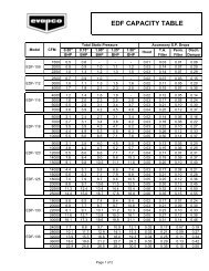
Recommended Steel SupportThe recommended support for EVAPCO Closed CircuitCoolers is structural “I”beams located under the outerflanges and running the entire length of the unit. Theunit should be elevated to allow access underneath theunit and to the roof below. Mounting holes, 3/4” indiameter are located in the bottom flanges of the pansection to provide for bolting to the structural steel.(Refer to certified drawings from the factory for bolthole locations.)Beams should be level before setting the unit in place.Do not level the unit by shimming between the unit andthe structural steel. Dimensions, weights, and data aresubject to change without notice. Refer to the factorycertified drawings for exact dimensions.Plan ViewsA<strong>ATW</strong> SUPPORTING STEEL DIMENSIONS4' Wide Models A B<strong>ATW</strong> 24 5’ 11-7/8”4’ 1/4”<strong>ATW</strong> 36 8’ 11-1/2”4’ 1/4”<strong>ATW</strong> 48 11’ 11-3/4”4’ 1/4”8-1/2' Wide Models A B<strong>ATW</strong> 64 8’ 5-1/2”7’ 5-7/8”<strong>ATW</strong> 77 8’ 11-1/2”8’ 5-1/2”<strong>ATW</strong> 89 10’ 5-1/2”8’ 5-1/2”<strong>ATW</strong> 102 11’ 11-3/4”8’ 5-1/2”<strong>ATW</strong> 119 13’ 11-3/4”8’ 5-1/2”<strong>ATW</strong> 153 18’ 0”8’ 5-1/2”<strong>ATW</strong> 179 21’ 0”8’ 5-1/2”4' to 12' WIDE MODELS12' Wide Models A B<strong>ATW</strong> 144 11’ 11-3/4”11’ 10”A17' and 24' WIDE MODELS<strong>ATW</strong> 168 13’ 11-3/4”11’ 10”<strong>ATW</strong> 216 18’ 0”11’ 10”<strong>ATW</strong> 240 20’ 0”11’ 10”<strong>ATW</strong> 286 24’ 2”11’ 10”<strong>ATW</strong> 334 28’ 2”11’ 10”<strong>ATW</strong> 430 36’ 2-1/2”11’ 10”<strong>ATW</strong> 478 40’ 2-1/2”11’ 10”17' Wide Models A BEnd ElevationsB4' to 12' WIDEMODELS<strong>ATW</strong> 204 11’ 11-3/4”17’ 1-1/2”<strong>ATW</strong> 238 13’ 11-3/4”17’ 1-1/2”24' Wide Models A B<strong>ATW</strong> 290 11’ 11-3/4”24’ 1-1/8”<strong>ATW</strong> 338 13’ 11-3/4”24’ 1-1/8”<strong>ATW</strong> 434 18’ 0”24’ 1-1/8”<strong>ATW</strong> 482 20’ 0”24’ 1-1/8”B<strong>ATW</strong> 578 24’ 2”24’ 1-1/8”<strong>ATW</strong> 672 28’ 2”24’ 1-1/8”<strong>ATW</strong> 866 36’ 2-1/2”24’ 1-1/8”<strong>ATW</strong> 960 40’ 2-1/2”24’ 1-1/8”17' and 24' WIDE MODELS21
SpecificationsFurnish and install as shown on the plans an EVAPCO Model_________ induced draft counterflow closed circuit cooler.Each unit shall have the capacity to cool _________ GPM of_______ from ______ °F to ______ °F with a _____ °F enteringwet bulb temperature.Basin and CasingThe basin and casing shall be constructed of G-235 hot-dipgalvanized steel for long life and durability. Standard basinaccessories shall include overflow, drain, type 304 stainlesssteel strainers, and brass make-up valve with plastic float.Direct Drive Models 4’ WideFan Motor_________ horsepower totally enclosed fan cooled fanmotor(s), with 1.25 service factor shall be furnished suitable foroutdoor service on ________ volts, _________ hertz, and_________ phase.DriveThe fan shall be mounted on the motor in a direct driveconfiguration.Belt Drive Models 8-1/2’ & 17’ WideFan Motor_________ horsepower totally enclosed fan cooled motorswith 1.15 service factor shall be furnished suitable for outdoorservice on _________ volts, _________ hertz, and _________phase. Motor(s) shall be mounted on an adjustable basewhich is accessible from the outside of the unit for service. Aswing away protective cover shall shield the motor andsheave from the weather.DriveThe fan drive shall be multigroove, solid back V-belt typewith taper lock sheaves designed for 150% of the motornameplate horsepower. The belt material shall be neoprenereinforced with polyester cord and specifically designed forevaporative cooler service. Fan sheave shall be aluminumalloy construction. The fans and the fan sheaves shall bemounted on the shaft with a specially coated bushing toprovide maximum corrosion protection. Belt adjustmentshall be accomplished from the exterior of the unit. Bearinglube lines shall be extended to the exterior of the unit foreasy maintenance.Belt Drive Models 12’ & 24’ WideFan Motor_________ horsepower totally enclosed air over ball bearingfan motor(s), with 1.15 service factor shall be furnishedsuitable for service on _________ volts, _________ hertz, and_________ phase. Motor(s) shall be mounted on an adjustablebase which allows the motor to swing to the outside of theunit for servicing.DriveThe fan drive shall be a multigroove, solid back V-belt typewith taper lock sheaves designed for 150% of the motornameplate horsepower. The belt material shall be neoprenereinforced with polyester cord and specifically designed forevaporative cooler service. Fan and motor sheaves shall bealuminum alloy construction. The fans and fan sheaves shallbe mounted on the shaft with a specially coated bushing toprovide maximum corrosion protection. Belt adjustmentshall be accomplished from the exterior of the unit. Bearinglube lines shall be extended to the exterior of the unit foreasy maintenance.Axial Propeller FansFans shall be heavy duty axial propeller type staticallybalanced. The fans shall be constructed of aluminum alloyblades, installed in a closely fitted cowl with venturi air inlet.Fan screens shall be galvanized steel mesh and frame, boltedto the fan cowl.Fan Shaft BearingsFan shaft bearings shall be heavy duty self-aligning ball typewith grease fittings extended to the outside of the unit.Materials shall be stainless steel balls with chrome steel racesand zinc plated housing for corrosion resistance. Bearingsshall be designed for a minimum L-10 life of 75,000 hours.Water Recirculation PumpThe pump(s) shall be a close-coupled, centrifugal type withmechanical seal, installed vertically at the factory to allow freedrainage on shut down. _________ horsepower totallyenclosed motor(s) shall be furnished suitable for outdoorservice on _________ volts, _________ hertz, and _________phase.Heat Transfer CoilCooling coil(s) shall be all prime surface steel, encased in asteel framework and hot-dip galvanized after fabrication as acomplete assembly. The tubes shall be arranged in a selfspacing,staggered pattern in the direction of airflow formaximum heat transfer efficiency and minimum pressuredrop, without the use of additional spacers between the coiltubes. The coil(s) shall be pneumatically tested at 400 psig,under water.Water Distribution SystemThe system shall provide a water flow rate of not less than 6GPM over each square foot of unit plan area to ensure properflooding of the coil. The spray header shall be constructed ofschedule 40 polyvinyl chloride pipe for corrosion resistance. Allspray branches shall be removable for cleaning. The watershall be distributed over the entire coil surface by precisionmolded ABS spray nozzles (1-1/4” x 5/16” orifice) with internalsludge ring to eliminate clogging. Nozzles shall be threadedinto spray header to provide easy removal for maintenance.EliminatorsThe eliminators shall be constructed entirely of inert polyvinylchloride (PVC) in easily handled sections. The eliminatordesign shall incorporate three changes in air direction toassure complete removal of all entrained moisture from thedischarge air stream. Maximum drift rate shall be less than0.001% of the circulating water rate.LouversThe louvers shall be constructed from polyvinyl chloride(PVC). The louvers shall be mounted in easily removableframes for access to the pan for maintenance. The louversshall have a minimum of two changes in air direction toprevent splashout and block direct sunlight.FinishAll basin and casing materials shall be constructed of G-235heavy gauge mill hot-dip galvanized steel. Duringfabrication, all panel edges shall be coated with a 95% purezinc-rich compound for superior protection againstcorrosion.24