ApplicationsDesignEVAPCO units are of heavy-duty construction and designedfor long trouble-free operation. Proper equipment selection,installation and maintenance is, however, necessary toensure full unit performance. Some of the majorconsiderations in the application of a cooler are presentedbelow. For additional information, contact the factory.Air CirculationIt is important that proper air circulation be provided. Thebest location is on an unobstructed roof top or on groundlevel away from walls and other barriers. Those closed circuitcoolers located in wells, enclosures or adjacent to high wallsmust be properly located to avoid the problems associatedwith recirculation.Recirculation raises the wet bulb temperature of the enteringair causing the water temperature to rise above the design.For these cases, the discharge of the fan should be located ata height even with the adjacent wall, thereby reducing thechance of recirculation. For additional information, see theEVAPCO Equipment Layout Manual.Good engineering practice dictates that the closed circuitcooler discharge air not be directed or located close to or inthe vicinity of building air intakes.PipingCooler piping should be designed and installed in accordancewith generally accepted engineering practices. The pipinglayout should be symmetrical on multiple unit systems, andsized for a reasonably low water velocity and pressure drop.The standard closed circuit cooler is recommended only on aclosed, pressurized system. The piping system should includean expansion tank to allow for fluid expansion and purgingair from the system.Note: Closed Circuit Coolers should never be used on anopen type system. An open type system with a cooler mayresult in premature coil failure.The piping system should be designed to permit completedrainage of the heat exchanger coil. This will require avacuum breaker or air vent to be installed at the high pointand a drain valve installed at the low point of the pipingsystem. Both must be adequately sized.All piping should be securely anchored by properly designedhangers and supports. No external loads should be placedupon the cooler connections, nor should any of the pipesupports be anchored to the cooler framework.Recirculating Water SystemThe surest way to protect the recirculating water system fromfreezing is with a remote sump. The remote sump should belocated inside the building and below the unit. When aremote sump arrangement is selected, the spray pump isprovided by others and installed at the remote sump. Allwater in the closed circuit cooler basin should drain to theremote sump when the spray pump cycles off. Refer to page23 for concept illustration.Other freeze protection methods are available when a remotesump is not feasible. Electric pan heaters, steam or hot watercoils can be used to keep the pan water from freezing whenthe unit cycles off. Water lines to and from the unit, spraypump and related piping should be heat traced and insulatedup to the overflow level in order to protect from freezing.The unit should not be operated dry (fans on, pump off) unlessthe basin is completely drained and the unit has beendesigned for dry operation. Consult the factory when dryoperation is a requirement.Freeze ProtectionIf the units are installed in a cold climate and operated yearround,freeze protection must be provided for the heatexchanger coil in the unit as well as for the recirculatingwater system.Heat Exchanger CoilThe simplest and most foolproof method of protecting theheat exchanger coil from freeze-up is to use a glycol solution.If this is not possible, an auxiliary heat load must bemaintained on the coil at all times so that the watertemperature does not drop below 50°F when the cooler isshut down. Also, a minimum recommended flow rate mustbe maintained. Refer to Heat Loss Data Table on page 27 forheat loss data.Minimum Flows4' Wide Models GPM<strong>ATW</strong> 24, 36, 48 708-1/2' Wide Models<strong>ATW</strong> 64, 77, 89, 102,175119, 153, 17912' Wide Models<strong>ATW</strong> 144, 168, 216, 240,286, 334, 430, 47840017' Wide Models<strong>ATW</strong> 204, 238 35024' Wide Models<strong>ATW</strong> 290, 338, 434, 482 400<strong>ATW</strong> 578, 672, 866, 960 800Water TreatmentIn some cases the make-up water will be so high in mineralcontent that a normal bleed-off will not prevent scaling. Inthis case, water treatment will be required and a reputablewater treatment company familiar with the local waterconditions should be consulted.Any chemical water treatment used must be compatible withthe galvanized construction of the unit. If acid is used fortreatment, it should be accurately metered and theconcentration properly controlled. The pH of the water shouldbe maintained between 6.5 and 8.0. Batch chemical feeding isnot recommended because it does not afford the properdegree of control. If acid cleaning is required, extreme cautionmust be exercised and only inhibited acids recommended foruse with galvanized construction should be used.Control of Biological ContaminationWater quality should be checked regularly for biologicalcontamination. If biological contamination is detected, amore aggressive water treatment and mechanical cleaningprogram should be undertaken. The water treatmentprogram should be performed in conjunction with a qualifiedwater treatment company. It is important that all internalsurfaces be kept clean of accumulated dirt and sludge. Inaddition, the drift eliminators should be maintained in goodoperating condition.Units constructed of galvanized steel operating withcirculating water having a pH of 8.3 or higher will requireperiodic passivation of the galvanized steel to prevent theformation of “white rust”.25
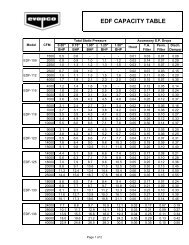
Discharge Hoods with PositiveClosure DampersWhen a closed circuit cooler is used in a water-to-air heatpump system or in certain process cooling applications, amethod of reducing the heat loss during idle periods ofwintertime operation may be required. For these cases, anoptional discharge hood with positive closure dampers anddamper actuator is available.The discharge hood with dampers is designed to minimizethe heat loss from convective airflow through an idle cooler.Further reductions in heat loss may be obtained with theaddition of insulation to the hood and casing, minimizingconductive heat losses. Insulation may be factory installedon the hood and casing or field installed by an insulationcontractor.The discharge hood and dampers are constructed of hot-dipgalvanized steel. Hoods are equipped with access panels tofacilitate maintenance of the eliminators and waterdistribution system. The dampers, damper actuator andlinkage are all factory assembled. Actuator controls andwiring are field supplied by others. Damper actuatorsrequire 120 volt power supply.The system control sequence should provide for dampers tobe fully open before the fans are running and closed whenthe fans are off; the damper actuator must be interlockedwith the temperature control system for this purpose.Heat loss data is provided for standard units without hoods,with hoods and with hoods and insulation. Table ratings arebased on 50°F water in the coil, -10°F ambient and 45 MPHwinds (fan and pump off). Refer to page 27.Discharge Hood DimensionsNumberModel L H* W Weight of Hoods<strong>ATW</strong> 24 5’ 11-7/8”1’ 6” 4’ 1/4” 400 1<strong>ATW</strong> 36 8’ 11-1/2”1’ 6” 4’ 1/4” 560 1<strong>ATW</strong> 48 11’ 11-3/4”1’ 6” 4’ 1/4” 710 1<strong>ATW</strong> 64 7’ 5-7/8”1’ 4”8’ 5-1/2”830 1<strong>ATW</strong> 77 8’ 11-1/2”1’ 4”8’ 5-1/2”1,000 1<strong>ATW</strong> 89 8’ 11-1/2”1’ 4”8’ 5-1/2”1,000 1<strong>ATW</strong> 102 8’ 11-1/2”1’ 4”8’ 5-1/2”1,000 1<strong>ATW</strong> 119 8’ 11-1/2”1’ 4”8’ 5-1/2”1,000 1<strong>ATW</strong> 153 8’ 11-1/2”1’ 4”8’ 5-1/2”2,000 2<strong>ATW</strong> 179 8’ 11-1/2”1’ 4”8’ 5-1/2”2,000 2<strong>ATW</strong> 204 8’ 11-1/2”1’ 4”8’ 5-1/2”2,000 2<strong>ATW</strong> 238 8’ 11-1/2”1’ 4”8’ 5-1/2”2,000 2<strong>ATW</strong> 144 11’ 11-3/4”1’ 2” 11’ 10” 1,700 1<strong>ATW</strong> 168 11’ 11-3/4”1’ 2” 11’ 10” 1,700 1<strong>ATW</strong> 216 11’ 11-3/4”1’ 2” 11’ 10” 1,700 1<strong>ATW</strong> 240 11’ 11-3/4”1’ 2” 11’ 10” 1,700 1<strong>ATW</strong> 286 11’ 11-3/4”1’ 2” 11’ 10” 3,400 2<strong>ATW</strong> 290 11’ 11-3/4”1’ 2” 11’ 10” 3,400 2<strong>ATW</strong> 334 11’ 11-3/4”1’ 2” 11’ 10” 3,400 2<strong>ATW</strong> 338 11’ 11-3/4”1’ 2” 11’ 10” 3,400 2<strong>ATW</strong> 430 11’ 11-3/4”1’ 2” 11’ 10” 3,400 2<strong>ATW</strong> 434 11’ 11-3/4”1’ 2” 11’ 10” 3,400 2<strong>ATW</strong> 478 11’ 11-3/4”1’ 2” 11’ 10” 3,400 2<strong>ATW</strong> 482 11’ 11-3/4”1’ 2” 11’ 10” 3,400 2<strong>ATW</strong> 578 11’ 11-3/4”1’ 2” 11’ 10” 6,800 4<strong>ATW</strong> 672 11’ 11-3/4”1’ 2” 11’ 10” 6,800 4<strong>ATW</strong> 866 11’ 11-3/4”1’ 2” 11’ 10” 6,800 4<strong>ATW</strong> 960 11’ 11-3/4”1’ 2” 11’ 10” 6,800 4* Overall unit height will be height of the base unit plus the Hdimension.LWH26