A new method for perspective correction of document images
A new method for perspective correction of document images
A new method for perspective correction of document images
- No tags were found...

You also want an ePaper? Increase the reach of your titles
YUMPU automatically turns print PDFs into web optimized ePapers that Google loves.
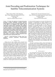
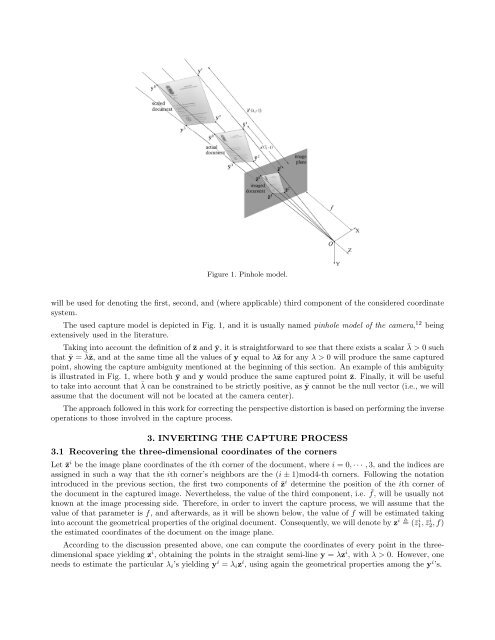
Figure 1. Pinhole model.will be used <strong>for</strong> denoting the first, second, and (where applicable) third component <strong>of</strong> the considered coordinatesystem.The used capture model is depicted in Fig. 1, and it is usually named pinhole model <strong>of</strong> the camera, 12 beingextensively used in the literature.Taking into account the definition <strong>of</strong> ¯z and ȳ, it is straight<strong>for</strong>ward to see that there exists a scalar ¯λ > 0 suchthat ȳ = ¯λ¯z, and at the same time all the values <strong>of</strong> y equal to λ¯z <strong>for</strong> any λ > 0 will produce the same capturedpoint, showing the capture ambiguity mentioned at the beginning <strong>of</strong> this section. An example <strong>of</strong> this ambiguityis illustrated in Fig. 1, where both ȳ and y would produce the same captured point ¯z. Finally, it will be usefulto take into account that ¯λ can be constrained to be strictly positive, as ȳ cannot be the null vector (i.e., we willassume that the <strong>document</strong> will not be located at the camera center).The approach followed in this work <strong>for</strong> correcting the <strong>perspective</strong> distortion is based on per<strong>for</strong>ming the inverseoperations to those involved in the capture process.3. INVERTING THE CAPTURE PROCESS3.1 Recovering the three-dimensional coordinates <strong>of</strong> the cornersLet ¯z i be the image plane coordinates <strong>of</strong> the ith corner <strong>of</strong> the <strong>document</strong>, where i = 0, · · · ,3, and the indices areassigned in such a way that the ith corner’s neighbors are the (i ± 1)mod4-th corners. Following the notationintroduced in the previous section, the first two components <strong>of</strong> ¯z i determine the position <strong>of</strong> the ith corner <strong>of</strong>the <strong>document</strong> in the captured image. Nevertheless, the value <strong>of</strong> the third component, i.e. ¯f, will be usually notknown at the image processing side. There<strong>for</strong>e, in order to invert the capture process, we will assume that thevalue <strong>of</strong> that parameter is f, and afterwards, as it will be shown below, the value <strong>of</strong> f will be estimated takinginto account the geometrical properties <strong>of</strong> the original <strong>document</strong>. Consequently, we will denote by z i (¯z i 1, ¯z i 2,f)the estimated coordinates <strong>of</strong> the <strong>document</strong> on the image plane.According to the discussion presented above, one can compute the coordinates <strong>of</strong> every point in the threedimensionalspace yielding z i , obtaining the points in the straight semi-line y = λz i , with λ > 0. However, oneneeds to estimate the particular λ i ’s yielding y i = λ i z i , using again the geometrical properties among the y i ’s.