BMW Bluetooth Kit Installation Instructions for BMW 3 Series / M3 ...
BMW Bluetooth Kit Installation Instructions for BMW 3 Series / M3 ...
BMW Bluetooth Kit Installation Instructions for BMW 3 Series / M3 ...
- No tags were found...

You also want an ePaper? Increase the reach of your titles
YUMPU automatically turns print PDFs into web optimized ePapers that Google loves.
2PARTS INFORMATION:Description Qty <strong>BMW</strong> Part NumberULF Control Module 1 84 21 6 934 552Voice Input System Jumper Plug 1 84 11 0 018 038ULF Control Module Mounting Bracket (Touring) 1 84 13 6 924 698E46 Sedan/Coupe/Touring <strong>Installation</strong> <strong>Kit</strong> 1 84 11 0 302 639<strong>Installation</strong> <strong>Kit</strong> Contents:M5 Bolt w/washer 6 07 11 9 902 932M5 Hex Nut 6 63 21 1 371 401M5 Clip Nut 4 61 13 1 372 033Wire tie 2 61 13 1 367 599ULF Control Module Mounting Bracket1 84 13 6 924 553(if rear carrier brackets are installed)Microphone 1 84 31 8 380 319<strong>Bluetooth</strong> TM Antenna 1 84 50 6 928 461<strong>Bluetooth</strong> TM Antenna Mounting Bracket 1 84 13 6 912 160Pairing Button 1 84 13 0 302 715Adapter Harness 1 84 11 0 302 181ULF Pairing Button Cutout Template 1 84 11 0 304 482ULF Owner’s Manual 1 84 11 0 302 638ULF Passkey Reference Card 1 84 11 0 302 646ULF E46 <strong>Installation</strong> <strong>Instructions</strong> 1 84 11 0 302 643Owner’s Manual For Voice Input System 1 84 11 0 027 942PROCEDURE:To install and connect the <strong>BMW</strong> Universal <strong>Bluetooth</strong> TM Hands-Free SystemDisconnect Battery prior to starting the installation.A. <strong>Bluetooth</strong> TM Antenna & Pairing Button <strong>Installation</strong>1. Remove the rear ashtray and disconnect theillumination light (2).2. Remove two Phillips screws (3) and remove therear ashtray assembly (1).
623. Insert the Pairing Button, P/N 84 13 0 302 715,into the cutout and reinstall the cupholders andcoin tray.B. ULF Control Module <strong>Installation</strong>1. Remove/ peel off the <strong>Bluetooth</strong> TM Passkey sticker(2) from the label on the ULF Control Module (1).2. Place the <strong>Bluetooth</strong> TM Passkey sticker removedfrom the ULF Control Module onto the ULFPasskey Reference Card, P/N 84 11 0 302 638.3. Place this card inside the owner’s manualportfolio. Show this card to the customer whendemonstrating the system and the pairingprocedure to the customer. The code on thesticker is needed to pair phones to the ULFControl Module.
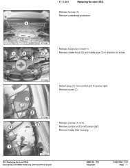
84. Prior to connecting the black 54-pin connector tothe ULF Control Module pins 7 & 8 will need to beremoved from the connector and tied back.Note: Pins 7& 8 provide a wheel speed inputsignal that is not utilized by the ULF ControlModule and need to be disconnected from thecontrol module.5. Open the connector by pushing out on the locktap(s) (1) and slide the terminal housing (2) out ofthe connector housing.6. Locate pins 7 & 8 (2) and carefully remove themfrom the terminal housing (1).7. Bend the wires <strong>for</strong> pin 7 & 8 back away from theconnector8. Wrap each terminal separately with electrical tapeand tape them to the wiring harness.9. Reassemble the connector.10. Connect the 54-pin connector (2) and whiteFAKRA connector (1) to the ULF Control Module(F).
911. Insert the ULF Control Module and bracket (1) intothe opening in the inner area of the rear quarterpanel, and place the bracket against the innerportion of the support structure.12. The three threaded lugs on the mounting bracketshould be inserted through the three holes in thesupport structure (2).13. Secure the bracket (G) in place using three M5hex nuts (J), P/N 63 21 1 371 401.14. Reinstall the felt panel (1) and componentsremoved previously.
10E46 Sedan with Carrier Rack1. If the left rear of the trunk is as shown, then acomponent carrier rack is already installed and thefollowing steps should be followed.2. If the trunk is not as shown refer to the installationsteps <strong>for</strong> no carrier rack installed, on page 12.3. Remove the left rear trim panel.4. Locate the black 54-pin connector and whiteFAKRA connector bundle (1), near the left rearwheel well housing.5. Route the 54-pin connector and white FAKRAconnector along the right side of the componentcarrier rack (2), making certain that the 54 pinconnector and white FAKRA connector can beconnected to the ULF Control Module asindicated in the following steps.6. Prior to connecting the black 54-pin connector tothe ULF control Module pins 7 & 8 will need to beremoved from the connector and tied back. (Wiresare only present on vehicles produced as of 8/02)Note: Pins 7& 8 provide a wheel speed inputsignal that is not utilized by the ULF ControlModule and need to be disconnected from thecontrol module.7. Open the connector by pushing out on the locktap(s) (1) and slide the terminal housing (2) out ofthe connector housing.
1214. Connect the 54-pin connector (2) and whiteFAKRA connector (1) to the ULF Control Module(F) after the bracket is installed.E46 Sedan With No Carrier Rack15. Reinstall the left rear trim panel.IMPORTANT: In the event a vehicle is not equippedwith a carrier bracket the trunk will look as indicated inthe illustration.1. Remove left rear trim panel.2. Remove the securing bolt (1) <strong>for</strong> the amplifiersecuring bracket and the clip-nut3. Locate the telephone connector bundle (2).
1411. Bend the wires <strong>for</strong> pin 7 & 8 back away from theconnector12. Wrap each terminal separately with electrical tapeand tape them to the wiring harness.13. Reassemble the connector.14. Locate the black 54-pin connector and whiteFAKRA connector.15. Slide the ULF control module (1) into the openarea behind the amplifier.15. Secure the ULF Control Module (1) to the interiorof the support structure using two M5 hex bolts (2& 3), P/N 07 11 9 902 932.16. Reinstall the trim panel
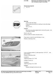
15C. <strong>Installation</strong> of Voice Input Jumper1. If a Voice Input Jumper Plug is not installed then aJumper Plug, P/N 84 11 0 018 038, must beobtained and installed <strong>for</strong> the system to functioncorrectly. The jumper plug should be installedonto a blue 26 pin connector that is located nearthe black 54 pin connector <strong>for</strong> the ULF module.Note: The Jumper plug is not included in the kitas this plug may already be installed on somevehicles.D. <strong>Installation</strong> of Microphone1. Carefully pull down the access panel (1).2. Locate the black 3-pin connector X18507 that istaped to the harness.3. Install microphone (E) P/N 84 31 8 380 319, withthe arrow on the microphone pointing to the frontof the vehicle, into the microphone fret andconnect X4221 to the microphone.4. In the event of a customer complaint indicatingthat the outgoing audio from the vehicle soundsdistant, the location of the microphone andsunroof switch can be reversed to place themicrophone closer to the driver.Reconnect the Battery
17F. Troubleshooting:SituationNo audio output through vehicle speakersRadio does not mute after placing a callCorrectionCheck SES module jumper plugCheck connections at rear of radio <strong>for</strong> Tel On andTel Mute signal. Verify that connectors and pinsare properly seated.Audio quality in vehicle may not sound very good - Recode ULF Control Module.- NOTE: Audio quality in vehicle or at personbeing contacted, is dependent on the qualityand signal strength of the wireless serviceprovider in the area traveled.Customer complains that the person beingcontacted hears a “Buzzing” noise, at times duringtheir conversation or on voice mail message thathe/she has left.Driver is told that the person being contactedcomplains that there is an echo/reverberation inthe audio; person can hear his/her voice backthrough the phone.A second call is received while in a call, and callcannot be accepted using MFL controls.The radio audio does not come back immediatelyif the “other” person hangs up first.Customer is not able to pair phone to system, notable to locate ULF passkey/password referencecard.Intermittently a popping noise is audible throughthe vehicles speaker and there is no <strong>Bluetooth</strong> TMwireless communication established between theULF module and the phone.E46 Only:After installation of ULF system the speedometerand odometer do not work.Intermittently a “Buzzing” noise is noticeable to theperson being called from the vehicle. The“Buzzing” noise is a result of the GSM signal beingfeedback through the microphone, this usuallyoccurs if the GSM phone is located too close tothe microphone. The customer should change thelocation of where the phone is placed/stored.Audio volume in vehicle during a call may be a bitto loud, causing the other person to hear his/hervoice coming back through the phone.Use handset to expect second call and placeprevious called on hold. Call waiting is functionalonly via the handset.It takes approximately 15 seconds <strong>for</strong> the ULFsystem to recognize that the call was terminatedfrom outside the vehicle.If the call is terminated from outside the vehiclefirst, the driver can depress the button on thesteering wheel to terminate the call from thevehicle and unmute the radio quicker.- The “<strong>Bluetooth</strong> TM Passkey” is identified on thelabel of the ULF Control Module located in therear of the vehicle.- The “<strong>Bluetooth</strong> TM Passkey” <strong>for</strong> the installedcontrol module can be obtained by connectingthe DISPlus or GT1and accessing thediagnostics <strong>for</strong> the ULF system:- select “Diagnostic requests”- select “<strong>Bluetooth</strong> code”- Vehicle and /or ULF Control Module are notcorrectly coded.- Recode module and vehicle (refer to CodingULF Control Module to Vehicle)Remove pin 7 & 8 from the 54-pin connectorgoing to the ULF Control Module. Refer to theE46 installation instructions.
18G. Pairing Procedure:The pairing procedure that must be initiated through the phone will differ corresponding to the differentmenu configurations of the various <strong>Bluetooth</strong> TM mobile phones on the market. The user’s manual of thephone should always be referenced <strong>for</strong> specific steps on how to activate the <strong>Bluetooth</strong> TM feature and topair/link devices.The following steps are generalized steps that should help in activating the <strong>Bluetooth</strong> TM function of mostphones:IN VEHICLE:1. Depress the pairing button <strong>for</strong> at least 1second prior to switching on the ignition andcontinue to hold the button down <strong>for</strong>approximately 2-3 seconds after the ignition isturned on.2. Release the button.3. Shortly after releasing the button the Radio or Board Monitor display should look like one of thefollowing:a. Board Monitor Display:• “<strong>Bluetooth</strong> Pairing” displayed.• Green, Yellow and Red LEDs on theright side of the unit are flashing whichindicates that the ULF is searching <strong>for</strong>available <strong>Bluetooth</strong> TM devices.4. Activate the search function of the phone as indicated below.ON PHONE:1. Locate the connection/settings menu and select <strong>Bluetooth</strong> TM .2. Select the response that will activate the <strong>Bluetooth</strong> TM feature of the phone.b. Radio Display:• “BT Pairing” display which indicatesthat the ULF is searching <strong>for</strong> available<strong>Bluetooth</strong> TM devices.3. Next select a menu option that will allow you to “Discover” or “Search” <strong>for</strong> active <strong>Bluetooth</strong> TMdevices.
20COMPONENT LOCATION:SPORT WAGONSEDANA - Eject BoxD - <strong>Bluetooth</strong> TM AntennaC/E - MicrophoneF - ULF Control Module
21ULF Wiring Schematic <strong>for</strong> the E46with Boardmonitor30 RF395AF75ALightSwitchinput<strong>Bluetooth</strong>AntennaX10015X100163X4545X9988InterfaceSwitchnot in use2 1 13X45451735X13016Cradle Key +Cradle On32 11+5VX01185X9987ULFControlModule36211913738335115X01185Ground DistributionMicrophone Shield210 11Microphone -83Microphone +2 3 191X2759X18507SESJumperPlug26 25 23X10390Tel +Tel -Telephone OnTelephone Mute13 12 18 X103906 12 X13649 1110from terminal 30 from terminal RF41F715 16 X13646RadioControlModuleI/K Busto other modulesfrom terminal 30F41from terminal RF7LightSwitchinput12X1364621 87X136499X13646X13016MicrophoneoutputtospeakerX13016TAPEL -4TAPEL +TAPER -TAPER +3 9 10I/K Bus6to other modules7 11 1X18801BoardmonitorSpeaker2X18801X13016Schematic in<strong>for</strong>mationobtained / developed usingschematics from DIS v 32.0