9XTend-PKG-R™ RS-232/485 RF Modem
9XTend-PKG-R™ RS-232/485 RF Modem
9XTend-PKG-R™ RS-232/485 RF Modem
- No tags were found...

You also want an ePaper? Increase the reach of your titles
YUMPU automatically turns print PDFs into web optimized ePapers that Google loves.
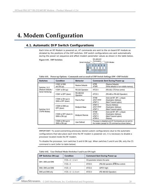
<strong>9XTend</strong>‐<strong>PKG</strong>‐R <strong>RS</strong>‐<strong>232</strong>/<strong>485</strong> <strong>RF</strong> <strong>Modem</strong> – Product Manual v1.2.44. <strong>Modem</strong> Configuration4.1. Automatic DIP Switch ConfigurationsEach time an <strong>RF</strong> <strong>Modem</strong> is powered on, AT commands are sent to the on-board <strong>RF</strong> module asdictated by the positions of the DIP switches. DIP switch configurations are sent automaticallyduring the power-on sequence and affect modem parameter values as shown in the table below.Figure 4‐01. DIP SwitchesTable 4‐01. Power‐up Options ‐ Commands sent as result of DIP Switch Settings (SW = DIP Switch)Switches Condition Behavior Commands Sent During Power-upSwitches 1 & 2(Restore Defaults /Serial Interfacing)Switches 5 & 6(TX/RX Modes)If SW1 & SW2are ON (up)Restore DefaultsATREATWR(Restore Defaults)(Write defaults to non-volatile memory)If SW1 is ON (up) <strong>RS</strong>-<strong>232</strong> Operation ATCS 0 (<strong>RS</strong>-<strong>232</strong>, CTS flow control)If SW1 is OFF (down)If SW5 is ON (up) &SW6 is OFF (down)If SW5 & SW6 areOFF (down)If SW5 is OFF (down) &SW6 is ON (up)If SW5 is ON (up) &SW6 is ON (up)<strong>RS</strong>-<strong>485</strong>/422OperationPeer-to-PeerMultipoint BaseMultipoint RemoteUser DefinedATCS 3(<strong>RS</strong>-<strong>485</strong> or <strong>RS</strong>-422 Operation)ATAM (Auto-set MY, MY = unique)ATDT FFFF (Destination Address)ATMT 3 (Multi-Transmit option)ATMY 0 (Source Address)ATDT FFFF (Destination Address)ATMT 3 (Multi-Transmit option)ATAM (Auto-set MY, MY = unique)ATDT 0 (Destination Address)ATMT 0 (Multi-Transmit option)ATRR A (Retries)Processor is disabled and AT Commands are not sent tothe modem (except for CS command as shown below.)IMPORTANT: To avoid overwriting previously stored custom configurations (due to the automaticconfigurations that take place each time the <strong>RF</strong> modem is powered-on), it is necessary to disable aprocessor located inside the <strong>RF</strong> modem.To disable the processor, turn switches 5 and 6 ON (up). When switches 5 and 6 are ON, only the CScommand is sent [refer to table below].Table 4‐02. User Defined Mode (Switches 5 and 6 are ON (up))DIP Switches ON (up) Condition Command Sent During Power-upSW1, SW5 and SW6If CS = 0, 1, 2 or 4CS parameter remains the sameIf CS = 3 ATCS 0 (<strong>RS</strong>-<strong>232</strong> operation, flow control)SW2, SW5 and SW6 If CS = 2 ATCS 2 (GPO1 high)SW5 and SW6 only If CS = 0, 1, 2, 3 or 4 ATCS 3 (<strong>RS</strong>-<strong>485</strong>/422 Operation)© 2005 MaxStream, Inc. Confidential and Proprietary 20