9XTend-PKG-R™ RS-232/485 RF Modem
9XTend-PKG-R™ RS-232/485 RF Modem
9XTend-PKG-R™ RS-232/485 RF Modem
- No tags were found...
You also want an ePaper? Increase the reach of your titles
YUMPU automatically turns print PDFs into web optimized ePapers that Google loves.
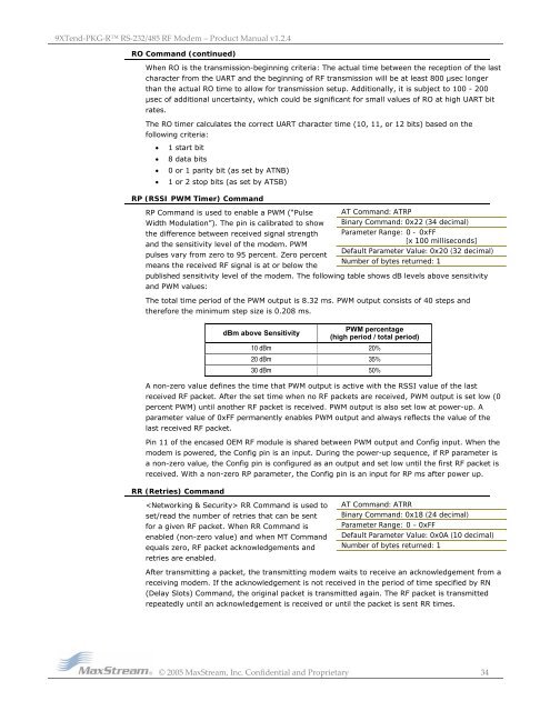
<strong>9XTend</strong>‐<strong>PKG</strong>‐R <strong>RS</strong>‐<strong>232</strong>/<strong>485</strong> <strong>RF</strong> <strong>Modem</strong> – Product Manual v1.2.4RO Command (continued)When RO is the transmission-beginning criteria: The actual time between the reception of the lastcharacter from the UART and the beginning of <strong>RF</strong> transmission will be at least 800 µsec longerthan the actual RO time to allow for transmission setup. Additionally, it is subject to 100 - 200µsec of additional uncertainty, which could be significant for small values of RO at high UART bitrates.The RO timer calculates the correct UART character time (10, 11, or 12 bits) based on thefollowing criteria:• 1 start bit• 8 data bits• 0 or 1 parity bit (as set by ATNB)• 1 or 2 stop bits (as set by ATSB)RP (<strong>RS</strong>SI PWM Timer) CommandRP Command is used to enable a PWM (“PulseWidth Modulation”). The pin is calibrated to showthe difference between received signal strengthand the sensitivity level of the modem. PWMpulses vary from zero to 95 percent. Zero percentmeans the received <strong>RF</strong> signal is at or below thepublished sensitivity level of the modem. The following table shows dB levels above sensitivityand PWM values:AT Command: ATRPBinary Command: 0x22 (34 decimal)Parameter Range: 0 - 0xFF[x 100 milliseconds]Default Parameter Value: 0x20 (32 decimal)Number of bytes returned: 1The total time period of the PWM output is 8.32 ms. PWM output consists of 40 steps andtherefore the minimum step size is 0.208 ms.dBm above SensitivityPWM percentage(high period / total period)10 dBm 20%20 dBm 35%30 dBm 50%A non-zero value defines the time that PWM output is active with the <strong>RS</strong>SI value of the lastreceived <strong>RF</strong> packet. After the set time when no <strong>RF</strong> packets are received, PWM output is set low (0percent PWM) until another <strong>RF</strong> packet is received. PWM output is also set low at power-up. Aparameter value of 0xFF permanently enables PWM output and always reflects the value of thelast received <strong>RF</strong> packet.Pin 11 of the encased OEM <strong>RF</strong> module is shared between PWM output and Config input. When themodem is powered, the Config pin is an input. During the power-up sequence, if RP parameter isa non-zero value, the Config pin is configured as an output and set low until the first <strong>RF</strong> packet isreceived. With a non-zero RP parameter, the Config pin is an input for RP ms after power up.RR (Retries) Command RR Command is used toset/read the number of retries that can be sentfor a given <strong>RF</strong> packet. When RR Command isenabled (non-zero value) and when MT Commandequals zero, <strong>RF</strong> packet acknowledgements andretries are enabled.AT Command: ATRRBinary Command: 0x18 (24 decimal)Parameter Range: 0 – 0xFFDefault Parameter Value: 0x0A (10 decimal)Number of bytes returned: 1After transmitting a packet, the transmitting modem waits to receive an acknowledgement from areceiving modem. If the acknowledgement is not received in the period of time specified by RN(Delay Slots) Command, the original packet is transmitted again. The <strong>RF</strong> packet is transmittedrepeatedly until an acknowledgement is received or until the packet is sent RR times.© 2005 MaxStream, Inc. Confidential and Proprietary 34


