MULTI S400 - Seatronic
MULTI S400 - Seatronic
MULTI S400 - Seatronic
- No tags were found...

Create successful ePaper yourself
Turn your PDF publications into a flip-book with our unique Google optimized e-Paper software.
Warning<strong>S400</strong> advanSea instruments comply with regulations in force.ImportantIt is the owner’s sole responsibility to ensure that this appliance is installed and usedin such a way that will not cause any accidents, personal injury or property damage.The user of this appliance is solely responsible for observing safe boating practices.Installation: if not installed correctly, the appliance will not operate to the best ofits ability. In the event of doubt, please contact your advanSea retailer. Ensure thatall holes made to mount the appliance are drilled in places without risk and that theydo not weaken the structure of the boat. If in doubt, contact a qualified boatbuilder.PLASTIMO SHALL NOT BE HELD LIABLE IN THE EVENT THE USE OF THISAPPLIANCE CAUSES ACCIDENTS, DAMAGE OR INFRINGEMENT OF THE LAW.Reference language: this statement, instruction and user manuals and otherinformation documents regarding the appliance, hereinafter referred to as"documentation", may be translated into other languages. In the event of a disputeregarding interpretation of the documentation, the French version shall be binding.This manual presents the procedures for installing and operating the appliance atthe date of printing. AdvanSea reserves the right to modify the technicalcharacteristics of the appliance without notice.Copyright © 2009 Plastimo, France, all rights reserved. AdvanSea TM is aregistered trademark of Plastimo.
Table of contents1. Introduction1.1. General presentation ........................................ p.41.2. Components supplied with your Multi<strong>S400</strong> ......... p.51.3. Technical characteristics ................................... p.52. General operation2.1. Powering on ..................................................... p.72.2. Operation in normal mode ................................ p.72.2.1. Selecting information on the upper display2.2.2. Selecting information on the lower display2.2.3. Selecting units of measurement2.2.4. Resetting data2.2.5. Countdown timer2.2.6. Backlighting2.3. Alarms ............................................................. p.102.3.1. Setting the echo sounder alarm thresholds2.3.2. Setting the speed alarm thresholds2.3.3. Setting the battery alarm threshold2.4. Configuration.................................................... p.122.4.1. Keel offset2.4.2. Speed damping2.4.3. Calibrating the water temperature2.4.4. Calibrating by speed2.4.5. Calibrating by log2.4.6. Configuring the countdown timer2.4.7. Simulation mode2.4.8. Key beeps2.4.9. Resetting data in the memory2.5. Standby ........................................................... p.152.6. Network operation (Bus AS-1) ........................... p.162.7.1. Displaying multiple data2.7.2. Remote access2.7. Messages ......................................................... p.17Installation and Operation Manual <strong>S400</strong> series 2
3. Installation3.1. NMEA 0183 interfacing...................................... p.183.1.1. NMEA 0183 input interface3.1.2. NMEA 0183 output interface3.2. Mounting and connections................................. p.193.2.1. Mounting the Multi <strong>S400</strong> unit3.2.2. Description of electrical connections3.2.2.1. Bus connection3.2.2.2. Speed connection3.2.2.3. Sounder connection3.2.2. Connections4. Troubleshooting ...................................... p.22Installation and Operation Manual <strong>S400</strong> series 3
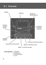
1 IntroductionThank you for choosing an AdvanSea product. We are convinced your <strong>S400</strong>instrument will provide you with many safe and happy years of navigation. Thismanual describes how to install and operate the Multi <strong>S400</strong> AdvanSea.1.1. General presentationDescription of the display:The <strong>S400</strong> unit is equipped with a large screen, and large characters for optimumreadability from all angles of vision. The screen is treated against condensation toprevent the formation of mist. The screen and its keys are backlit with adjustablelevel.Upper line(32mm characters)Lower line(22mm characters)- Menusalarms andconfiguration- Backlightingsetup- Validation- Standby-Lower display- Decrease- Change units- Upper display- Increase- Change unitsThe LCD screen on your Multi <strong>S400</strong> is designed to: display the surface speed of the boat display the water temperature display the depth display the battery voltage acquire data through its NMEA input send data via its NMEA output exchange data on the AS-1 AdvanSea bus activate external lights and buzzersInstallation and Operation Manual <strong>S400</strong> series 4
To do so, it is supplied with 3 connection cables: 1 connector-free cable for the power supply, the bus, the NMEA IN & OUT, the alarmoutput 1 LT8 cable for connection to the speedometer sensor 1 RCA cable for connection to the sounder sensorThe Multi <strong>S400</strong> is part of the <strong>S400</strong> advanSea family of navigation instruments,including instruments for measuring speed, depth, and wind. They may beconnected together to form an integrated data system for a boat (see chapter 2.7).<strong>S400</strong>1.2. Components supplied with your MultiThe Multi <strong>S400</strong> comes with (as standard):- protective cover- user manual- warranty card- adhesive rear sealing joint for flush mountingThe Multi <strong>S400</strong> does not come with sensors. You can order complete kits, orconsult our website www.advanSea.com.You will also find a complete list of accessories at www.advanSea.com1.3. Technical characteristicsMeasurement characteristicsSounder:Speed:Trip log:Total log:Measurement range: from 0.5 to 199 metersOperating frequency: 200 kHzAccuracy: ±0.1 meter up to 5.0 meters and 2% beyond 5.0meters (this accuracy is given for a constant sound speed inwater of 1490 m/s)Resolution: 0.1 from 0 to 19.9 and 1 beyondConfigurable offset: ±9.9 metersMeasurement range: from 0.0 to 60.0 knotsSpeed ratio: fixed at 6.1 Hz/knotsAccuracy: ±1.0 knots up to 20.0 knots and ±5% beyond 20.0knots.Resolution: 0.01 from 0 to 19.99 and 0.1 beyondCalibration possible on 2 measurement points (Slope and Offset)Measurement range: from 0.00 to 655.35 kilometresResolution: 0.01Measurement range: from 0 to 65535 kilometresResolution: 1Installation and Operation Manual <strong>S400</strong> series 5
Battery voltage: Measurement range: from 10.0V to 16.5VAccuracy: ±0.2VResolution: 0.1VElectrical specificationsBuzzer output(green wire):NMEA 0183:Switched to ground, open collector, 30 V DC and 300 mA max.It is recommended to protect this output with a 300 mA fuse.Version 3.01, asynchronous 4800 baud, 8 bit link, withoutparity, 1 stop bit. The electrical levels used on the NMEA outputare referenced to the ground and vary according to the system’svoltage supply.On powering on, a proprietary NMEA frame $PNKEV,<strong>MULTI</strong>V0.10*4A is sent to identify the transmitter.Communicationbus:Half-Duplex 38400 baud link on one wire. Words are sent on 8bits, without parity with 1 stop bit. The number of devicesconnected to the bus is limited to 20.Power supply: 9 volts to 16.5 volts / Consumption
2 General operation2.1. Powering onThe <strong>MULTI</strong> <strong>S400</strong> display does not include an integrated switch. The unit is poweredby a 12 V DC supply on the red (+) and black (-) wires. When stopped, all settingsare memorized.2.2. Operation in normal mode2.2.1. Selecting information on the upper displayThekey is used to select various data in the upper line. Key operation:DepthDEPTHSpeed over ground (if connected to a GPS)SOGBoat speedSPEEDAv erage speedAVG SPEE DMax speedMAX SPEEDTemperatureTEMPInstallation and Operation Manual <strong>S400</strong> series 7
2.2.2. Selecting information on the lower displayThekey is used to select various data in the lower line. Key operation:Regatta stopwatchCHRONOBattery voltageBATTrip logLOGTotal logTotal LOGTemperatureTEMPDepthDEPTHBoat speedSPEEDAverage speedAVG SPEEDMaximum speedMAX SPEEDInstallation and Operation Manual <strong>S400</strong> series 8
2.2.3. Selecting units of measurementTo change the unit of measurement for some data in the upper line, press at least 2seconds on the key.To change the unit of measurement for some data in the lower line, press at least 2seconds on the key.The following table summarizes the various units displayed according to the dataselected:DataUnit of measurementTemperature °Fahrenheit °CelsiusDepth Feet MetresSpeed over groundBoat speedAverage speedKnots km/h Miles/hMax speedTrip logTotal logNautical Miles Kilometres MilesIn bold, default units.2.2.4. Resetting dataTo reset the average speed and max speed data on the upper line, first display theparameter to be reset to 0 and press simultaneously at least 2 seconds on the+ keys.To reset the average speed, max speed, Trip log and Total log data on the lowerline, first display the parameter to be reset to 0 and press simultaneously at least 2seconds on the + keys.Installation and Operation Manual <strong>S400</strong> series 9
2.2.5. Countdown timerOnce CHRONO is displayed on the lower line, trigger it by pressing simultaneouslyon the + keys.The countdown starts from the data displayed (which can be configured between 1and 10 minutes, see menu paragraph 2.5.6.). A long beep signals when thecountdown switches to the full minute. The end of the countdown is signalled by ashort beep every second for the last 5 seconds followed by a long beep to mark theend of the countdown.When the countdown is finished, the countdown timer counts the navigation time inhours/minutes (with two points flashing per second).Press again simultaneously for at least 2 seconds on the + keys duringthe countdown to stop it and reset the display to the selected value.2.2.6. BacklightingThe display and the 4 keys are backlit, with 4 levels of intensity. Level"0" corresponds to backlighting switched off.To control backlighting:Press the key to display the backlighting page, then the andkeys to adjust the lighting level from 0 to 4.Pressing again on the key send the lighting level on the bus tocontrol backlighting on other device displays.2.3. AlarmsThe icon is lit when at least one alarm has occurred on one item of datamanaged by the <strong>MULTI</strong> display. A sensor alarm appears when it is activated(different from 0) and the measurement has exceeded the high or low thresholdpreviously defined. This alarm is then shown by: The flashing icon The data concerned by the alarm flashing, Automatic lighting of the LCD backlighting to its highest level, The internal buzzer sounds, The buzzer or the external lights are activated.Installation and Operation Manual <strong>S400</strong> series 10
An alarm can be cancelled and inhibited for 3 minutes by pressing on any key on thekeypad. After this period, a new alarm may be triggered when the measurementsensor once again exceeds the programmed thresholds.Several devices interconnected on the bus, can be used to relay a sensor alarm toother compatible displays present on the network. Example: a boat speed alarm canbe viewed on all "<strong>MULTI</strong>" displays present on board.The Depth and Boat speed data can be monitored by configuring high and low alarmthresholds.The Battery voltage data can be monitored by configuring the low threshold alarm.2.3.1. Setting the depth alarm thresholdsPress menu , then once again on menu to display the "dEEP" highthreshold page for the sounder, then adjust the required value of thethreshold using the and keys.Press to exit setup mode, or time out after 10 seconds.menuPress , then once again on menu to display the "SHAL" lowthreshold page for the sounder, then adjust the required value of thethreshold using the and keys.Press to exit setup mode, or time out after 10 seconds.2.3.2. Setting the speed alarm thresholdsPress menu , then once again on menu to display the "SPEEd " lowthreshold page for the speed, then adjust the required value of thethreshold using the and keys.Pressto exit setup mode, or time out after 10 seconds.Press menu , then once again on menu to display the "SPEEd " highthreshold page for the speed, then adjust the required value of thethreshold using the and keys.Press to exit setup mode, or time out after 10 seconds.Installation and Operation Manual <strong>S400</strong> series 11
2.3.3. Setting the battery alarm thresholdThe battery alarm allows you to monitor the supply voltage to your installation. Thisis important, particularly for good sounder performance.menuPress , then once again on menu to display the "bAt" lowthreshold page, then adjust the required value of the threshold usingthe and keys.Press to exit setup mode, or time out after 10 seconds.2.4. Configuration2.4.1. Keel offsetThe depth displayed on the Multi display represents the distance between the probemounted on the hull and the bottom, plus or minus the keel offset: For a positive offset, the depth is measured from a point located abovethe probe (Depth = distance between probe and bottom + Offset). For a negative offset, the depth is measured from a point located belowthe probe (Depth = distance between probe and bottom - Offset).To adjust this offset:Press menu for 2 seconds, then on menu until the "kEEL offset page isdisplayed, then adjust the required value using the andkeys.Press to exit setup mode, or time out after 10 seconds.2.4.2. Speed dampingA damping coefficient is available to the user for boat speed. Depending onnavigation conditions, this parameter can be adjusted to between 1 and 30.Press menu for 2 seconds, then on menu until the "dAMP" setup pageis displayed, then adjust the required value using the andkeys.Pressto exit setup mode, or time out after 10 seconds.Installation and Operation Manual <strong>S400</strong> series 12
2.4.3. Calibrating the water temperatureThe water temperature is calibrated in the calibration menu, by replacing the watertemperature displayed with the water temperature estimated by the user, ormeasured using another source.Press menu for 2 seconds, then on menu until the "tEMP" setup pageis displayed, then adjust the required value using the andkeys.Pressto exit setup mode, or time out after 10 seconds.2.4.4. Calibrating by speedThe speedometer sensor can be calibrated by speed or by distance.The boat speed is calibrated in the calibration menu, by replacing the boat speeddisplayed with the boat speed estimated by the user, or measured using anothersource.We recommend you navigate at constant speed. Note the speed displayed on a GPSreceiver (it should be greater than 5 kts) or measure the time taken to cover a givendistance (speed between 5 and 20 kts, in calm seas, with little current).Press menu for 2 seconds, then on menu until the "SPEEd" setup pageis displayed, then adjust the required value using the andkeys.Press to exit setup mode, or time out after 10 seconds.2.4.5. Calibrating by logAfter resetting the Trip log to "0", cover a specific set distance (identified on achart). To partly compensate for current and tide effects, cover the distance in bothdirections, parallel to the current.In the calibration menu, replace the distance displayed for the Trip log with the realdistance covered.Press menu for 2 seconds, then on menu until the "LOG" setuppage is displayed, then adjust the required value using theand keys (max. ±50% adjustment of the value measured bythe Trip log).Press to exit setup mode, or time out after 10seconds.Installation and Operation Manual <strong>S400</strong> series 13
2.4.6. Configuring the countdown timerThe duration of the countdown can be configured to the nearest minute, between 1and 10 minutes.Press menu for 2 seconds, then on menu until the "tIME" setup pageis displayed, then adjust the required value using the andkeys.Pressto exit setup mode, or time out after 10 seconds.2.4.7. Simulation modeSimulation mode can be accessed via the Configuration menu. This mode is shownby the iconflashing on the LCD and remains active after power has beencut off. It may be used for sales demonstrations of the product and features thefollowing functions:Displays a coherent bottom profile (in distance and variation),Displays a coherent boat speed (in absolute value and in acceleration),Displays a speed over ground related to the simulated boat speed,Displays a coherent water temperature,Displays the real supply voltage,Transmits simulated data via the NMEA output.Transmits simulated data via the communication bus.menuPress for 2 seconds, then menuuntil the "SIMUL" page isdisplayed, then activate (on) or deactivate (OFF) simulation using theand keys.Pressto exit setup mode, or time out after 10 seconds.2.4.8. Key beepsThe key beeps can be activated or deactivated.menuPress for 2 seconds, then menuuntil the "bIP" page isdisplayed, then activate (on) or deactivate (OFF) the beep using theand keys.Pressto exit setup mode, or time out after 10 seconds.Installation and Operation Manual <strong>S400</strong> series 14
2.4.9. Resetting data in the memoryAt any time, the memory of the Multi display can be returned to factory settings. Todo so, a memory reset command is accessible in the menu. The followingparameters are restored in the memory: Speed unit: Knots Depth unit: Metres Distance unit: Nautical Miles Temperature unit: °Celsius Speed damping: 10 seconds Speed calibration coeff.: Slope at 1.0 Temp. calibration coeff.: Offset to 0 Keel offset: 0 Depth alarms: deactivated, high and low threshold at0 Speed alarms: deactivated, high and low threshold at0 Temperature alarms: deactivated, high and low threshold at0 Battery alarm: deactivated, low threshold at 0 Countdown timer init.: 10 minutes Trip log: 0 Total log: 0 Simulation mode: deactivated Backlighting level: 0 (OFF)Press menu for 2 seconds, then menu until the "rESEt" page isdisplayed, then activate (on) or deactivate (OFF) the reset usingthe and keys.Pressto exit setup mode, or time out after 10 seconds.2.5. StandbyTo save energy on board, the "<strong>MULTI</strong>" display can be placed on standby by pressingfor 5 seconds on the key.Standby mode switches off backlighting, the screen, stops sensor measurement andprocessing of NMEA input and output interfaces. Only the vital bus management andkeyboard functions remain active. Active displays present on the bus indicatemeasurement impossible with an OFF icon instead of the data.Installation and Operation Manual <strong>S400</strong> series 15
Standby mode is not saved. At any time, simply pressing one of the four keysor cutting off the power stops standby mode and returns all devicefunctions to normal.2. 6. Network operation (Bus AS-1)The AS-1 bus is used to connect products in the advanSea family via a rapid andreliable exchange protocol. Only the bus wires need to be connected. No start-upsettings are required.The communication protocol allows for multiple data exchange at previously definedtransmission speeds.Thus, it is possible: to exchange several similar measurements on the same bus, forexample: several speedometer sources. to change the units, the alarm threshold values or to calibrate from asingle instrument. to activate or deactivate alarms from a single instrument.The protocol allows exchange of similar data from different sources (directmeasurement from the sensor, or from the bus or via NMEA).2.6.1. Displaying multiple dataIn order to display multiple data, a repeater instrument (without a sensor) should bedifferentiated from a measurement instrument (with a sensor or receiving NMEAdata).A repeater instrument can display maximum 2 multiple data available on the bus(for example: port speed and starboard speed). If there are more than 2 multipledata present on the bus (for example 3 speed sensors), the repeater will only readthe information from the 2 measurement instruments with the lowest serialnumbers.A measurement instrument (with a sensor or receiving NMEA data) will only displaythe data from its own sensor or from the NMEA source received, even if othersimilar data are available on the bus.2.6.2. Remote accessA repeater instrument (without a sensor) can read and write, via AS-1 bus, all thecalibration parameters or the alarm thresholds from the same type of measuringinstrument. Thus, it is possible to calibrate the speed from the <strong>MULTI</strong> displayconnected to the bus.Installation and Operation Manual <strong>S400</strong> series 16
System limitation:For complex installations, with several similar measurement instruments, it isimpossible to calibrate alarms from a repeater instrument. In this case, thesesettings can only be adjusted from the measurement unit (display to which thesensor is connected).2.7. MessagesThere are 3 event messages which automatically disappear after 5 minutes or simplyby pressing a key:Err Bat Displayed each time a power drop near the 9V threshold is detected(safety threshold). Returns to normal if the battery exceeds this security level after afew seconds.Err MEM Displayed on powering on if a memory malfunction occurs.Err Bus Displayed at the first detection, after powering on, if a bus wire ispinched (incorrect wiring).Installation and Operation Manual <strong>S400</strong> series 17
3 Installation3.1. NMEA 0183 interfacingThe Multi <strong>S400</strong> display has one NMEA 0183 input and one output, non shielded. TheNMEA 0183 frame format recognized by the Multi display complies with the V3.01standard of January 2002.3.1.1. NMEA 0183 input interfaceThe NMEA 0183 input interface can simultaneously acquire the 5 physicalmeasurements listed in the table below. To avoid confusing the same data fromdifferent frames, a 3-levl priority management algorithm is used to prioritize someframes over others. Example: if the frames VTG and RMC are received, only the VTGframe will be decoded to receive the SOG data.NoNMEA dataFrames usedPriority 1 Priority 2 Priority 31 Boat speed VHW -- --2 Speed over ground VTG RMC --3 Depth DPT DBT --4 Log VLW -- --5 Water temperature MTW -- --Note: The data from the NMEA input are displayed with the icon.3.1.2. NMEA 0183 output interfaceThe Multi <strong>S400</strong>’s NMEA output emits at a speed of 1 Hz the 5 frames below:No NMEA frames Data transmitted1 VHW Boat speed --2 VLW Total log Trip log3 MTW Temperature --4 DBT Depth --5 DPT Depth --Note: The NMEA 0183 output does not repeat the frames received on its input.Installation and Operation Manual <strong>S400</strong> series 18
3.2. Mounting and connections3.2.1. Mounting the Multi <strong>S400</strong> unitThe Multi unit must be mounted in a visible location and protected from any risk ofshocks. It should be placed more than 10cm from a compass and more than 50cmfrom radio or radar antenna, far from all engines, fluorescent light, alternators andradio or radar transmitters. It should be accessible from the rear; minimum depthcabin side 50mm. The rear panel of the unit should be protected from humidity. Themounting surface should be flat and of thickness less than 20mm.Drill a hole 50mm in diameter at the chosen locationUnscrew the nut located on the rear of the unitRemove the adhesive protection around the unitInsert and position the unit in the mounting holeScrew back the nut3.2.2 . Description of electrical connections3.2.2.1. Bus connectionThe bus link is provided by a 7-wire shielded cable, arranged as follows: Red +12V DC Black GND / NMEA (-) Input and Output Orange bus Yellow NMEA input (+) White NMEA output (+) Green Buzzer and external light Blue NC3.2.2.2. Speed connectionThe connection with the speed sensor is provided by a 30 cm shielded cable, fittedwith an 8-pin connector with bayonet locking.Connector pins:1: Bare Ground2: Red +12V DC3: White Thermistor -4: Brown Thermistor +5: Yellow Sensor presence6: Green Paddlewheel7: Bare Sounder ground8: Colourless Sounder excitationInstallation and Operation Manual <strong>S400</strong> series 19
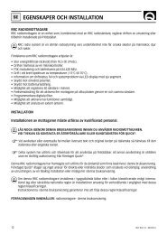
This connection is used to connect a multifunction sensor:Speed/Sounder/Temperature3.2.2.3. Sounder connectionConnection to the sounder sensor is via a 30 cm coaxial cable and an overmouldedRCA connector.3.2.3. ConnectionsConnect the sounder sensor to the RCA connectorConnect the speedometer sensor to the LT8 connectorConnect the - power to the black wire without connector and the redwire to the + power via a switch and a 1A fuse.For a system comprising several "Advansea" instruments, connect all theorange bus wires from each instrument together.Connect an NMEA source (GPS for example) to the yellow wire for the+nmea and the black for the – nmeaSee diagram below:Installation and Operation Manual <strong>S400</strong> series 20
Alimentation 12V power supply 12 volts + -menuBusme nuBuzzer ouBuzzer lampe or light+ -- +Entrée NMEA NMEA input+-Sortie NMEA NMEAoutputCapteur Depth sondeur transducerCapteur Speed speedo transducerInstallation and Operation Manual <strong>S400</strong> series 21
4. TroubleshootingThis troubleshooting guide assumes that you have read and understood this manual.It is possible in many cases to solve difficulties without the need for the after-salesservice. Please read this chapter carefully before contacting your AdvanSea retailer.1. The unit will not power on: Fuse melted or circuit breaker triggered. Voltage too low Power cable disconnected or damaged.2. Wrong or incoherent speed reading: Calibration incorrect Speed sensor cable disconnected or damaged Speed/temperature sensor damaged. Check thepaddlewheel. Incorrect mounting or sensor not sufficiently immersed.Review the installation. Electrical interference. Review the installation.3. Wrong or incoherent depth reading: The unit cannot detect the sea bottom momentarily,because the depth is too high or too low, due to lack ofwater clarity, reverse manoeuvring or rough seas. Sensor cable disconnected or damaged. Dirty or damaged sensor. Check that the sensor is notcovered with too thick a coat of paint. Sensor incorrectly mounted or not sufficiently immersed. Ultrasound signal interference from another sensor. Electrical interference. Review the installation.It is recommended to do a test with another working sensor (hold itunder water near the boat) to check if the sounder and the on-boardsensor are working correctly.4. Wrong temperature reading: Calibration incorrect. Speed/temperature sensor cable damaged.5. SIMU flashing on the screen, with incoherent readingsdisplayed. Unit in simulation mode (see 2.5.7).If the problems continue, we recommend you contact your advanSea retailer or ourcustomer support department. All contacts can be found at www.advansea.com.Installation and Operation Manual <strong>S400</strong> series 22
FRANCE & SWITZERLANDPlastimo France15 rue Ingénieur Verrière56100 LORIENT - FRANCETél : +33 (0)2 97 87 36 36Fax : +33 (0)2 97 87 36 49e-mail : plastimo@plastimo.fr UNITED KINGDOMNavimo UK LtdHamilton Business ParkBotley road – Hedge EndSouthampton, Hants. SO30 2HEPh: +44 1489 778 850Fax: +44 870 751 1950E-mail: sales@navimo.co.uk GERMANYNavimo Deutschland15 rue Ingénieur Verrière56100 LORIENT - FRANCETél : +33 (0)2 97 87 36 11Fax : +33 (0)2 97 87 36 29e-mail:sales.international@plastimo.fr ITALIANavimo Italia /Nuova Rade SpaVia del Pontasso 516015 Casella Scrivia (GE)Ph: +39 010 968 011Fax: +39 010 968 0150E-mail: info@nuovarade.com SWEDEN/DENMARK/NORWAY / FINLANDNavimo Nordic ABLundenvägen 2473 31 HENÅN - SWEDENPh: +46 (0)304 360 60Fax: +46 (0)304 307 43E-mail: info@navimo.se NETHERLANDS & BELGIUMNavimo Holland BvIndustrieweg 42871 JE SCHOONHOVENTHE NETHERLANDSPh: +31 (0)182 320522Fax: +31 (0)182 320519E-mail: info@plastimo.nl SPAINNavimo España SAPolígono industrial de CabreraCalle Industria s/n08349 CABRERA DE MAR BarcelonaPh: +34 93 750 75 04Fax: +34 93 750 75 34E-mail: plastimo@plastimo.es PORTUGALSiroco Representacôes Náuticas S.A.Zona industrial da Abrunheira,Armazem 22710-089 ABRUNHEIRA SINTRAPh: +351 21 915 4530Fax: +351 21 915 4540e-mail: Plastimo@plastimo.co.pt GREECEPlastimo Hellas1, 28th Octovriou str.& Kalogeropulou str.20 200 KIATO KORINTHIASTel/Fax: +30 27420 20 644E-mail : plastimo.hellas@plastimo.fr OTHER COUNTRIESPlastimo International/Export15 rue Ingénieur Verrière56100 LORIENT -FRANCETél : +33 (0)2 97 87 36 36Fax : +33 (0)2 97 87 36 49e-mail : sales.international@plastimo.frwww.advansea.com
<strong>S400</strong> SeriesGPS ComboadvanSea TM is a registered trademark of<strong>S400</strong> Series www.advansea.cominstruments – <strong>MULTI</strong> - Ref. 58111 – April 2009 – Rev. 1