OAA sound control-EN_mar15.qxd - SCHL
OAA sound control-EN_mar15.qxd - SCHL
OAA sound control-EN_mar15.qxd - SCHL

Create successful ePaper yourself
Turn your PDF publications into a flip-book with our unique Google optimized e-Paper software.
s<br />
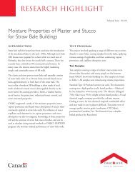
OBJECTIVES<br />
This article helps the reader to better<br />
understand:<br />
• The properties of <strong>sound</strong><br />
• The importance of <strong>sound</strong> <strong>control</strong><br />
to building quality and occupant<br />
satisfaction<br />
• Code requirements for <strong>sound</strong> <strong>control</strong><br />
• Airborne <strong>sound</strong> <strong>control</strong><br />
• Impact <strong>sound</strong> <strong>control</strong><br />
• Flanking <strong>sound</strong> <strong>control</strong><br />
OUND CONTROL IN MULTI-FAMILY<br />
WOOD-FRAME BUILDINGS<br />
by John Burrows and Barry Craig<br />
ABSTRACT<br />
Sound <strong>control</strong> in multi-unit residential construction affects occupant privacy and well-being. Insufficient <strong>sound</strong><br />
isolation can lead to lawsuits against architects and builders.<br />
This article explains how <strong>sound</strong> moves through buildings, and how designers can <strong>control</strong> airborne, impact and<br />
flanking noise transmission. It suggests ways to <strong>control</strong> <strong>sound</strong> in wood-frame, multi-family buildings and best<br />
practices for acoustic isolation.<br />
• Best design practices for <strong>sound</strong> <strong>control</strong><br />
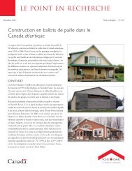
Source—Photo by Sandra Marshall<br />
March 2005<br />
Ontario<br />
Association<br />
of Architects
SOUND CONTROL IN MULTI-FAMILY WOOD-FRAME BUILDINGS<br />
INTRODUCTION<br />
Architects must consider many interacting factors in designing a building, including structural integrity,<br />
fire safety, energy efficiency and noise <strong>control</strong>. Understanding and implementing <strong>sound</strong> <strong>control</strong> has<br />
a major impact on occupants’ comfort, concentration and happiness, not to mention neighbourly<br />
relations. Sound <strong>control</strong> is particularly important in multi-unit residential construction.This article<br />
focuses on wood-frame construction in many Canadian multi-unit residences and briefly discusses<br />
masonry party walls.<br />
The rigid assemblies required to resist high wind loads or earthquakes make noise <strong>control</strong> difficult<br />
because they are pathways for <strong>sound</strong> vibrations. On the positive side, the sealing of penetrations to<br />
resist the spread of fire also blocks movement of certain kinds of <strong>sound</strong>. Some <strong>sound</strong> details reduce<br />
the spread of odours and pests and improve comfort and durability.<br />
This article examines airborne <strong>sound</strong>, such as loud music and impact <strong>sound</strong>, such as the thud of a dropped<br />
object. It describes the hidden routes that <strong>sound</strong> vibrations follow, such as leaks and flanking paths.<br />
The article summarizes information from the Best Practice Guide: Fire and Sound Control in Wood-Frame Multi-<br />
Family Buildings, published by Canada Mortgage and Housing Corporation (CMHC). 1 This guide brings<br />
together years of research from numerous sources, including the National Research Council of<br />
Canada’s Institute for Research in Construction (NRCC/IRC) and the experience of acoustic<br />
consultants.<br />
Sound transmission can be effectively <strong>control</strong>led in multi-family buildings by isolating neighbouring units<br />
from one another with proper walls and floors between suites.An architect should select wall or floor<br />
assemblies in multi-family housing for both resistance to fire spread—the fire-resistance rating—and<br />
resistance to the transmission of <strong>sound</strong> vibrations.Three indices—<strong>sound</strong> transmission class (STC), impact<br />
insulation class (IIC), and outdoor–indoor transmission class (OITC)—help designers select the suitable<br />
assemblies.<br />
However, choosing a good floor or wall assembly doesn’t guarantee acoustic privacy.To ensure the<br />
desired level of <strong>sound</strong> reduction, designers and builders must avoid any leaks and flanking paths, which<br />
are the gaps or short-circuits through which <strong>sound</strong> may travel.<br />
THE PROPERTIES OF SOUND<br />
Sound is defined as:<br />
“. . . vibrations which travel through the air or another medium and are sensed by the ear.” 2<br />
A vibrating object, such as a plucked guitar string, often initiates the fluctuations.The outwardly moving<br />
layers of compression and rarefaction of the air particles produce <strong>sound</strong> wave motion. Sound energy<br />
radiates in waves through an elastic medium, such as air, until it hits an obstruction and is transmitted,<br />
deflected, absorbed or dissipates through friction.<br />
As <strong>sound</strong> vibrations strike the eardrum and cause it to vibrate, hearing takes place.Annoying <strong>sound</strong>s in<br />
buildings are caused by:<br />
• People walking, talking and working<br />
• Televisions, audio systems and other entertainment equipment<br />
• Appliances, tools and equipment<br />
• HVAC equipment<br />
• Water and wastewater piping<br />
• Elevators and refuse chutes.<br />
1 Warnock,A.C.C., J.D. Quirt and M. Lio. Fire and Sound Control in Wood-Frame Multi-Family Buildings, Canada Mortgage and<br />
Housing Corporation, 2002. http://www.cmhc.ca/en/imquaf/himu/fisoco_001.cfm<br />
2 Pearsall, J. (Ed). Concise Oxford English Dictionary,Tenth Edition, Revised. Oxford University Press, 2002.<br />
2
SOUND CONTROL IN MULTI-FAMILY WOOD-FRAME BUILDINGS<br />
Frequency is a measure of the number of oscillations per second of particles set in motion by a <strong>sound</strong><br />
source.The more rapidly a <strong>sound</strong> source vibrates, the higher the <strong>sound</strong> pitch it makes. For example, a<br />
piccolo’s highest note has a frequency of approximately 5,000 Hz, whereas an upright bass can play as<br />
low as 40 Hz.<br />
Virtually all sources of <strong>sound</strong> produce several different frequencies simultaneously.To our ears,<br />
discordant or unwanted <strong>sound</strong> is noise.Young, healthy people can hear <strong>sound</strong> frequencies as low<br />
as 20 Hz and as high as 20,000 Hz.<br />
Low-frequency <strong>sound</strong>s are much more difficult to <strong>control</strong> in buildings and can be a major cause<br />
of complaints in multi-family buildings. Low-frequency <strong>sound</strong> vibrations move more easily through<br />
lightweight materials than heavy materials.A heavier wall or floor with the same <strong>sound</strong> rating as<br />
a lighter one may often absorb, or attenuate, more low-frequency <strong>sound</strong> than the lighter assembly.<br />
Conversely, high-frequency <strong>sound</strong> vibrations travel more freely through heavy materials, but are<br />
attenuated by lighter assemblies.<br />
The pressure that a <strong>sound</strong> wave exerts on a surface is measured in decibels (dB) as its <strong>sound</strong> pressure<br />
level.The larger the vibration of the source, and thus the disturbance of the air, the greater the <strong>sound</strong><br />
pressure level and the louder a <strong>sound</strong> is perceived by the ear.<br />
The human ear can perceive a range of <strong>sound</strong>s whose pressures vary by a factor of one million.<br />
Few people can discern a change in <strong>sound</strong> pressure less than 3 dB. Humans also perceive loudness<br />
differently at different frequencies. For these reasons, a logarithmic scale that corresponds to the<br />
human assessment of overall loudness was developed to measure the energy associated with a <strong>sound</strong><br />
wave.The units on the dBA scale are exponential. For example, an increment of 10 dBA is a doubling<br />
of perceived <strong>sound</strong> level.Table 1 shows typical <strong>sound</strong> levels for some common sources.<br />
Noise source Decibels (dBA)*<br />
Jet takeoff, artillery fire 120 or more<br />
Rock band or home theatre system 100–120<br />
Unmuffled truck or motorcycle 80–100<br />
Average radio or TV 70–90<br />
Human voice at 1m (3.2 ft.) 55–60<br />
Background in private office 35–40<br />
Quiet home 25–35<br />
Buzzing insect at 1 m (3.2 ft.) 15–25<br />
Threshold of hearing 0<br />
* Apparent loudness varies with the distance from the source<br />
Source—Warnock,A.C.C. , J.D. Quirt and M. Lio, Fire and Sound Control<br />
in Wood-frame Multi-family Buildings.<br />
Table 1—Sound pressure levels for common <strong>sound</strong><br />
When <strong>sound</strong> waves strike one side of a partition, pressure variations cause the face of the partition to<br />
vibrate as some of the power in the waves is transferred into the partition.A portion of this vibration<br />
energy reappears at the opposite side of the partition, where it is re-radiated as <strong>sound</strong>.The materials<br />
in the partition absorb part of the vibration energy, preventing some of the <strong>sound</strong> from re-radiating<br />
on the other side.This is the <strong>sound</strong> transmission loss of the assembly.<br />
3
SOUND CONTROL IN MULTI-FAMILY WOOD-FRAME BUILDINGS<br />
Sound vibrations from impact, such as those caused by a hammer dropped on a floor, can also pass<br />
through a building assembly. By understanding how <strong>sound</strong> behaves within a building, the designer can<br />
devise strategies to <strong>control</strong> it.<br />
AIRBORNE SOUND<br />
Sources such as voices and music produce airborne <strong>sound</strong>. It can originate in neighbouring rooms or from<br />
outside from sirens, machinery or traffic. Heavy layers that are not solidly connected at any point and<br />
that are separated by the thickest cavity possible effectively attenuate airborne <strong>sound</strong> in wall and floor<br />
assemblies. Attenuation improves when the cavity is filled with <strong>sound</strong>-absorbing material, such as insulation.<br />
The effectiveness of a wall or floor assembly in attenuating airborne <strong>sound</strong> transmission depends on<br />
the frequency of the <strong>sound</strong>. Most assemblies attenuate high-frequency <strong>sound</strong>s more effectively than<br />
low-frequency <strong>sound</strong>s.<br />
An assembly’s <strong>sound</strong> transmission class (STC) is a single numerical rating derived from <strong>sound</strong><br />
attenuations at various frequencies, which approximately describe a wall’s ability to attenuate the typical<br />
frequency content of speech. STC is a measure of the average noise reduction in decibels for speechlike<br />
<strong>sound</strong>s that pass through an assembly. An assembly with a high STC rating has good <strong>sound</strong><br />
attenuation characteristics.Table 2 shows how the STC ratings for walls relate to their ability<br />
to attenuate different types of <strong>sound</strong>.<br />
STC Noise source<br />
45<br />
50<br />
55<br />
Loud or amplified speech audible<br />
Loud music audible, bass notes particularly strong<br />
Loud or amplified speech faintly audible<br />
Loud music barely audible, but bass notes quite noticeable<br />
Loud music not generally audible, but bass notes<br />
still heard<br />
60 Loud music inaudible except for very strong bass notes<br />
Source—Warnock,A.C.C. , J.D. Quirt and M. Lio, Fire and Sound Control<br />
in Wood-frame Multi-family Buildings.<br />
Table 2—Effect of STC rating on audibility of speech<br />
and music<br />
Transportation noise from road traffic, trains and aircraft has greater low-frequency content than<br />
speech.The outdoor-indoor transmission class (OITC) is a single number rating of the attenuation of<br />
floor, wall and ceiling that better indicates the ability to attenuate transportation noise than the STC<br />
rating. Use OITC when considering intrusion of noise into a building from roads, trains or aircraft.<br />
STC ratings are available for most common assemblies as well as for windows and doors. NRC’s<br />
Laboratory Measurements of the Sound Insulation of Building Facade Elements 3 has OITC and STC ratings<br />
for common walls, roofs and windows.<br />
3 Bradley, J.S. and J.A. Birta. Laboratory Measurements of the Sound Insulation of Building Facade Elements, IRC Internal<br />
Report, IRCIR-818, 2000.<br />
4
SOUND CONTROL IN MULTI-FAMILY WOOD-FRAME BUILDINGS<br />
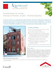
Assembly being tested<br />
Source room Receiving room<br />
Source—Warnock,A.C.C., J.D. Quirt and M. Lio. Fire and Sound<br />
Control in Wood-Frame Multi-Family Buildings<br />
Figure 1—Measuring <strong>sound</strong> transmission loss in the<br />
laboratory 4<br />
STC ratings are determined by<br />
testing assemblies under <strong>control</strong>led<br />
laboratory conditions. Noise is<br />
generated in the source room and<br />
the <strong>sound</strong> pressure levels are<br />
measured in both the source room<br />
and the receiving room over a range<br />
of frequencies (see Figure 1). Unlike<br />
real buildings, the only <strong>sound</strong><br />
transmission path between<br />
laboratory rooms is through the<br />
test wall or floor assembly, making<br />
it possible to accurately measure<br />
their <strong>sound</strong> attenuation properties.<br />
Sound pressure levels are measured<br />
and corrected to account for the<br />
acoustical properties of the receiving<br />
room. Floor assemblies are tested in<br />
a similar way, and there may also be<br />
impact tests to measure their<br />
impact insulation.<br />
The (STC) rating from these tests does not account for low-frequency <strong>sound</strong> transmission (below<br />
125 Hz), which may come from mechanical systems, elevators and the lower frequencies of amplified<br />
music.<br />
STC ratings cannot be simply added or subtracted.A 10 dB increase in the rating of a wall actually<br />
means it reduces the <strong>sound</strong> energy passing through the wall by 10 times, which the human ear<br />
perceives as being about half as loud.A wall with STC 45 will allow about 10 times more <strong>sound</strong> to<br />
pass than a wall with STC 55: this <strong>sound</strong>s about twice as loud in the receiving room.<br />
STC ratings of floors and walls can be measured in the field and given a field <strong>sound</strong> transmission class<br />
(FSTC) rating.To verify the intended acoustical privacy in a building, a field test can be done at an<br />
early stage in construction when all the essential components that make up the assembly are in place.<br />
It is useful for finding problems during construction, so that improvements can be made and errors can<br />
be avoided.<br />
The National Building Code of Canada (NBCC) now only regulates airborne <strong>sound</strong> transmission for<br />
interior wall and floor assemblies enclosing suites in multi-family buildings. It does not provide for<br />
protection from the transmission of impact <strong>sound</strong>s between suites or protection from outside airborne<br />
<strong>sound</strong>.The NBCC requires that walls and floors have an STC rating of:<br />
• 55 to separate residential suites from adjacent elevator shafts and refuse chutes (Sentences<br />
3.3.4.6.(3) and 9.11.2.1.(2)).<br />
• 50 to separate residential suites from every other space in a building (Sentences 3.3.4.6(2) and<br />
9.11.2.1.(1)).<br />
Tables A-9.10.3.1.A. and A-9.10.3.1.B. in Appendix A of the NBCC (1995) illustrate common assemblies<br />
for walls and floors, ceilings and roofs and their STC and fire ratings.The values assigned to the<br />
different assemblies can be used where a proposed design exactly replicates the listed assembly.This<br />
is important, since small construction differences may adversely affect expected performance.<br />
4 Bradley, J.S. and J.A. Birta. Laboratory Measurements of the Sound Insulation of Building Facade Elements, IRC Internal<br />
Report, IRCIR-818, 2000.<br />
5
SOUND CONTROL IN MULTI-FAMILY WOOD-FRAME BUILDINGS<br />
Nonetheless, some minor variance in ratings will always exist between actual field performance and<br />
laboratory-rated performance. Historically, provincial and local authorities have accepted ratings listed<br />
by the NBCC. However, the designer should confirm with the building officials in his or her jurisdiction<br />
that they accept these ratings.<br />
The most common situations requiring STC ratings are:<br />
• Party walls between residential suites<br />
• Walls between public corridors and residential suites<br />
• Floor assemblies between residential suites, mechanical rooms and recreation areas<br />
• Walls between residential suites and elevators, refuse chutes and service rooms<br />
IMPACT SOUND<br />
Good STC ratings do not necessarily satisfy occupants. Mechanical vibrations and impacts, such as foot<br />
traffic, dropped objects or objects sliding across a hard floor, also cause <strong>sound</strong> to move through<br />
construction materials. Although the code does not actually specify levels for impact ratings, it is<br />
important that architects design to reduce impact noise effects.<br />
A floor or wall being vibrated by direct mechanical contact or impact transmits impact <strong>sound</strong>.The<br />
vibration spreads along or through the wall or floor into the assembly and its cavities, ultimately becoming<br />
<strong>sound</strong> in adjoining spaces. Floor vibrations can also be transmitted through the structure to walls and be<br />
re-radiated as airborne <strong>sound</strong> into adjoining spaces.<br />
Impact <strong>sound</strong>s on concrete slabs finished with a hard surface, such as ceramic tile, are often described as<br />
“clacking” or “tapping.” Most of such <strong>sound</strong> energy occurs at high frequencies. Impact <strong>sound</strong>s on lightweight<br />
joist floors—the result of low-frequency <strong>sound</strong> waves—are usually described as “booming” or “thudding.”<br />
Although airborne and impact <strong>sound</strong> have some things in common, impact transmission is far more<br />
complicated to measure and <strong>control</strong>.The character and level of impact noise generated in a living space<br />
below depends on many factors, including the nature of the object striking the floor, the force of the blow,<br />
the rigidity of the floor assembly and the resilience of the floor covering. NRC is considering including<br />
impact noise requirements in future versions of the NBCC.<br />
The standard test for impact insulation class (IIC) uses a tapping machine that lifts and drops five steel<br />
hammers on a floor 10 times per second. Sound pressure levels are measured in the room below at<br />
specific frequencies.The higher the IIC, the better the attenuation of impact <strong>sound</strong>, with 50 dB usually<br />
considered the minimum for occupant satisfaction in residential buildings. However, the IIC test method<br />
ignores <strong>sound</strong>s generated at the lower frequencies (below 100 Hz). People walking on lightweight joist<br />
floors generate these low-frequency <strong>sound</strong>s, often at frequencies below the range used for the IIC rating.<br />
Thus, while a low IIC rating indicates that there will be annoyance due to impact <strong>sound</strong>, a high IIC rating<br />
does not guarantee there will be no problems from low-frequency <strong>sound</strong> through lightweight floors.<br />
As for airborne <strong>sound</strong>, it is important to understand that field performance can vary considerably because<br />
of factors on-site that are not present in the laboratory. Recommended practice is to specify assemblies<br />
with IIC and STC ratings 5 to 10 points higher than required to compensate for the lower performance<br />
in the field.Table 3 summarizes the minimum STC and IIC <strong>sound</strong> attenuation for various building<br />
assemblies that are recommended in CMHC’s Fire and Sound Control in Wood-Frame Multi-Family Buildings.<br />
The best practice is higher than the NBCC because the <strong>sound</strong> attenuation levels in completed buildings<br />
are often less than those produced in laboratory conditions.<br />
6
SOUND CONTROL IN MULTI-FAMILY WOOD-FRAME BUILDINGS<br />
Assemblies NBCC-required STC Best practice STC Best practice IIC<br />
Party walls or corridor walls 50 55 —<br />
Bare party floors 50 55 55<br />
Carpeted party floors 50 55 65<br />
Source—Warnock,A.C.C., J.D. Quirt and M. Lio. Fire and Sound Control in Wood-Frame Multi-Family Buildings<br />
Table 3—Minimum recommended STC and IIC ratings<br />
Impact <strong>sound</strong> insulation ratings depend greatly on the floor covering.The same basic floor structure can<br />
give extremely different IIC ratings depending on the surface layer. A floor design that relies on carpet and<br />
underpadding to <strong>control</strong> impact <strong>sound</strong> will be compromised if future occupants decide to remove the<br />
carpet. Some lightweight floors with an IIC of 55 dB or more may be subject to complaints because of<br />
low frequency and impact noise.Although carpet increases the IIC rating, it will not necessarily reduce<br />
low-frequency noise transmission. Good footstep noise rejection requires fairly heavy floor slabs or<br />
floating floors.<br />
Good detailing reduces impact <strong>sound</strong> transmission. However, the elimination of impact noise is nearly<br />
impossible because paths exist in all buildings that allow <strong>sound</strong> vibrations to bypass <strong>sound</strong> attenuation<br />
measures.These flanking paths have more serious consequences for impact <strong>sound</strong> than for airborne<br />
<strong>sound</strong>, because impacts transmit more vibration energy to the structure.Vibrations at low frequencies are<br />
more difficult to <strong>control</strong> in wood-frame construction because considerable mass is needed to attenuate<br />
this energy. Conversely, high-frequency <strong>sound</strong>s are difficult to <strong>control</strong> in concrete, masonry and steel<br />
structures, which require resilient connections to dissipate this energy.To be effective, <strong>sound</strong> <strong>control</strong><br />
measures must be suited to the type of construction.<br />
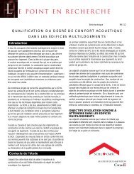
Sound<br />
source<br />
Flanking<br />
<strong>sound</strong><br />
Flanking<br />
<strong>sound</strong><br />
Figure 2—Flanking <strong>sound</strong> transmission<br />
Sound that is transmitted<br />
into an assembly can<br />
short–circuit the cavity<br />
through continuous layers<br />
of material at the top,<br />
bottom and side of the<br />
assembly<br />
Source—Warnock,A.C.C., J.D. Quirt and M. Lio. Fire and Sound<br />
Control in Wood-Frame Multi-Family Buildings<br />
FLANKING SOUND<br />
TRANSMISSION<br />
Flanking transmission consists of<br />
<strong>sound</strong> vibrations that bypass the<br />
<strong>sound</strong> attenuation components in<br />
wall or floor assemblies between<br />
rooms or suites to emerge as<br />
noise on the opposite side of the<br />
separation. Flanking exists in all<br />
buildings and its effect on apparent<br />
<strong>sound</strong> insulation (that perceived by<br />
the occupants) is influenced by the<br />
rigidity of the connections between<br />
walls, floors and their junctions.<br />
Indirect or flanking <strong>sound</strong> transmission<br />
occurs where the parts of a building<br />
are rigidly connected in hollow walls<br />
or floors and where continuous<br />
lightweight surfaces extend between<br />
apartments (see Figure 2). Flanking<br />
can undermine efforts to improve<br />
<strong>sound</strong> insulation and seriously reduce<br />
the apparent <strong>sound</strong> attenuation of<br />
walls and floors.<br />
7
SOUND CONTROL IN MULTI-FAMILY WOOD-FRAME BUILDINGS<br />
For the <strong>sound</strong> performance of the partition or floor to be fully realized, flanking transmission should not<br />
be permitted to be greater than direct transmission through the separating wall or floor assembly.<br />
Sound travels as vibrations along surfaces and through walls, ceilings and floors to adjacent rooms. Many<br />
paths other than the direct one through the party wall or floor may be involved.The use of gaps between<br />
sheathing surfaces, double stud walls, resilient metal channels and floating floors are some of the<br />
techniques for <strong>control</strong>ling flanking <strong>sound</strong> that will be presented later in this article.<br />
BARRIERS TO THE PASSAGE OF SOUND<br />
This section describes the main, proven-effective techniques for reducing airborne, impact and flanking<br />
<strong>sound</strong> transmission. A <strong>sound</strong> barrier must be impervious to air, non-porous, solid and reasonably<br />
heavy—materials such as gypsum board, glass, plywood, OSB and concrete are commonly used to<br />
reduce <strong>sound</strong> transmission in buildings.<br />
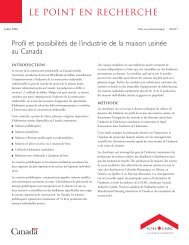
Heavy materials<br />
The density of materials has a large affect on <strong>sound</strong> transmission. Heavier, denser, building materials<br />
tend to block <strong>sound</strong> better than lightweight building materials (see Figure 3). A double-layer of gypsum<br />
wallboard or floor sheathing, for instance, provides better <strong>sound</strong> isolation than a single layer.<br />
Absorptive materials<br />
Heavy layers in wall assemblies do not<br />
vibrate as readily in response to <strong>sound</strong><br />
waves compared to lightweight layers.<br />
Source—Warnock,A.C.C., J.D. Quirt<br />
and M. Lio. Fire and Sound Control in Wood-<br />
Frame Multi-Family Buildings<br />
Figure 3—Heavy materials transmit less <strong>sound</strong><br />
Because wood-frame construction is<br />
relatively light, a combination of<br />
techniques is required to <strong>control</strong><br />
<strong>sound</strong>. An STC of 50 cannot be<br />
obtained with a single layer of<br />
gypsum board on each side of 89-mm<br />
wood studs because the combination<br />
of mass per unit area, cavity depth<br />
and stud stiffness is not sufficient to<br />
produce the required transmission<br />
loss. Doubling the mass of gypsum<br />
board on both sides of the stud wall<br />
increases the STC by about 9 dB<br />
(see NBCC Table A-9.10.3.1.A. (8)).<br />
The cavities inherent in wood-frame construction are a convenient space for absorptive material, such<br />
as fibrous insulation. Installing <strong>sound</strong>-absorbing material that fills at least two-thirds of the wall cavity<br />
can increase <strong>sound</strong> transmission loss by 8 to 10 dB if the surface layers are properly isolated.The<br />
insulation is only effective in absorbing <strong>sound</strong> waves within the cavity, so other measures are needed to<br />
reduce the <strong>sound</strong> passing through the framing.<br />
Absorptive materials are normally quite porous.They interact with <strong>sound</strong> passing through them,<br />
converting the vibrations into heat. Absorptive materials are not <strong>sound</strong> barriers.They reduce <strong>sound</strong><br />
energy in an enclosed cavity as <strong>sound</strong> repeatedly reflects between the enclosing surfaces and passes<br />
through the <strong>sound</strong>-absorbing material many times. Each pass-through causes a small decrease in energy,<br />
with the cumulative effect being significant. A single pass provides very little <strong>sound</strong> attenuation unless<br />
the absorbent material is very thick.Thus, adding a carpet or acoustic tiles directly to a surface will not<br />
significantly improve the <strong>sound</strong> insulation of the separation.<br />
8
SOUND CONTROL IN MULTI-FAMILY WOOD-FRAME BUILDINGS<br />
Vibration breaks and resilient connections<br />
In wood-frame construction, materials and techniques that isolate or decouple layers of materials can<br />
reduce both airborne and impact <strong>sound</strong>. Gypsum board that is solidly fastened to wood framing allows<br />
much of the <strong>sound</strong> to be transmitted through the frame.Therefore, it is beneficial to interrupt the solid<br />
connections between the gypsum board and the wall framing. Using flexible fasteners between the<br />
gypsum board and the framing will reduce the <strong>sound</strong> transmitted through the assembly.<br />
Staggered or double-stud walls (see Figure 4) are another way of isolating layers of materials. Staggered<br />
studs can increase the STC rating of a basic wood-frame wall by 10, and double studs can increase the<br />
STC rating of a basic wall by 20.<br />
Resilient connections in walls<br />
Resilient channels are flexible fasteners.They are commonly used to improve the <strong>sound</strong> insulation of<br />
walls and floors where the finish surfaces are attached to either side of the structural members. Adding<br />
resilient metal channels to at least one face of a single row of studs reduces <strong>sound</strong> transmission<br />
considerably and makes <strong>sound</strong>-absorbing material in the cavity more effective.<br />
Most resilient channels have a “Z” profile, and there is some variation in the design of the web that<br />
connects the two parallel attachment surfaces<br />
and the gauge of sheet metal used.Their purpose<br />
is to detach the drywall membrane from its<br />
supporting frame, so that <strong>sound</strong> vibrations<br />
cannot pass directly through the structure and<br />
wall surface. Because some <strong>sound</strong> will pass<br />
through the resilient channels, spacing them<br />
further apart results in greater <strong>sound</strong> reduction.<br />
Staggered Studs<br />
Double Studs<br />
Source—Warnock,A.C.C., J.D. Quirt and M. Lio. Fire and<br />
Sound Control in Wood-Frame Multi-Family Buildings<br />
Figure 4—Staggered and double-stud walls<br />
Resilient connections in floors<br />
Resilient materials used in floor assemblies can<br />
also reduce airborne and impact <strong>sound</strong>. Resilient<br />
channels on a ceiling reduce both airborne and<br />
impact <strong>sound</strong>. Coverings, such as carpet and<br />
underpad or floating floors, also <strong>control</strong> impact<br />
<strong>sound</strong>.<br />
Resilient channels are usually attached to the<br />
underside of floor joists at 400-mm (16-in.) or<br />
600-mm (24-in.) centres.The drywall ceiling<br />
membrane should be fastened to the resilient<br />
channels using screws long enough to penetrate<br />
the metal furring, but not so long that they<br />
penetrate the wood frame. Most channels will<br />
adequately support up to two layers of drywall<br />
with proper fastening. Because only a small<br />
amount of vibration energy passes through the<br />
channels, the <strong>sound</strong> attenuation of the floor<br />
assembly improves with increased resilient<br />
channel spacing.<br />
9
SOUND CONTROL IN MULTI-FAMILY WOOD-FRAME BUILDINGS<br />
Fibreboard<br />
spacer<br />
Caulking<br />
Floating slab<br />
Resilient material<br />
(felt, foam rubber<br />
or other proprietary<br />
material<br />
Source—Warnock,A.C.C., J.D. Quirt and M. Lio. Fire and Sound Control<br />
in Wood-Frame Multi-Family Buildings<br />
Figure 5. Resilient acoustic floor slab<br />
SEPARATION OF USES<br />
Building layouts should be designed<br />
with sensible vertical and horizontal<br />
separations between noise-generating<br />
spaces and spaces sensitive to transmitted<br />
<strong>sound</strong>. For example, elevators, garbage<br />
chutes, garage doors, plumbing, fans and<br />
heat pumps are common noise sources<br />
in buildings. Place them as far as possible<br />
from sensitive living areas, especially<br />
bedrooms.When it is practical to group<br />
kitchens and bathrooms together,<br />
concentrate plumbing noise in areas that<br />
are less sensitive.Avoid placing bedrooms<br />
above common-use automatic garage<br />
doors, or use <strong>sound</strong>-dampening<br />
components to isolate the door-opener<br />
and rollers from the building frame.<br />
Floor joist<br />
Plywood<br />
subfloor<br />
SOUND LEVELS (dB)<br />
A floating floor consists of a finish<br />
floor separated from the subfloor<br />
by a resilient material (see Figure 5).<br />
The floating floor can be a concrete<br />
topping, a laminated-gypsum concrete<br />
board or a lighter wood flooring,<br />
while the resilient layer can be a<br />
continuous blanket or pads. It is<br />
very important that there be no<br />
solid contact between the floating<br />
floor or wood raft and the subfloor,<br />
or the walls around their periphery.<br />
A resilient spacer or a gap with<br />
sealant between the floating floor<br />
and walls avoids direct <strong>sound</strong><br />
transmission.<br />
0<br />
Note: This data illustrates improvements in <strong>sound</strong> isolation for a<br />
specific building using proprietary components.These results may<br />
not necessarily be replicated in other buildings.<br />
Source—Cité BellevuePhase III, Quieter Condominiums<br />
Figure 6—Example of <strong>sound</strong> level improvements<br />
using resilient materials<br />
Vibrating parts should be isolated from the building structure with resilient materials, such as neoprene<br />
or rubber. Figure 6 shows how the retrofit of a multi-family building in Montréal used resilient <strong>sound</strong>proofing<br />
materials to improve <strong>sound</strong> <strong>control</strong>. 5<br />
SEALING<br />
The perimeters of all demising walls should be air-sealed to reduce airborne <strong>sound</strong> transmission<br />
through the assembly (see Figure 7), using a non-hardening, permanently resilient caulking on both sides<br />
of the partition. It is important to place the caulking where it can be seen and inspected before applying<br />
5 Cité BellevuePhase III, Quieter Condominiums, Canada Mortgage and Housing Corporation, http://www.cmhcschl.gc.ca/en/imquaf/himu/buin_016.cfm<br />
45<br />
40<br />
35<br />
30<br />
25<br />
20<br />
15<br />
10<br />
5<br />
Washer<br />
With Neoprene Pads<br />
Dryer<br />
With Neoprene Pads<br />
Dishwasher<br />
With Neoprene Pads<br />
Toilet<br />
With GLH Toilet Bowl<br />
Soundproofing Device<br />
10
SOUND CONTROL IN MULTI-FAMILY WOOD-FRAME BUILDINGS<br />
Gypsum board<br />
Subfloor<br />
Gypsum board<br />
Resilient metal furring<br />
Subfloor<br />
Source—Adapted from Warnock,A.C.C., J.D. Quirt and M. Lio. Fire and Sound Control in Wood-Frame Multi-Family Buildings<br />
Figure 7—Application of sealant to prevent <strong>sound</strong> leaks<br />
the drywall. Debris under the plate impairs effective sealing and must be cleared away before applying<br />
the sealant. Even small holes can seriously affect the performance of the wall. The bottom and top of<br />
drywall applied over block or solid concrete walls must also be sealed.<br />
The STC ratings shown in NBCC Table A-9.10.3.1. are for concrete block walls whose surfaces are<br />
sealed by at least two coats of paint or other finish, to prevent <strong>sound</strong> leakage.<br />
DESIGNING FOR SOUND CONTROL<br />
This section describes best practices for the selection of materials and installations that <strong>control</strong> the<br />
transmission of airborne and impact <strong>sound</strong>, and reduce noise transmitted by flanking paths. It is<br />
important to note that the <strong>sound</strong> attenuation provided by even the best assemblies for airborne and<br />
impact <strong>sound</strong> can be negated by inadequate <strong>control</strong> of flanking transmission.<br />
Airborne <strong>sound</strong><br />
Demising walls<br />
Wall assemblies designed to attenuate airborne <strong>sound</strong> should incorporate:<br />
• Two or more layers that are not connected at any point by solid materials and provide a degree<br />
of air-tightness<br />
• The heaviest layers that are practical<br />
• The deepest cavity that is practical, filled with <strong>sound</strong>-absorbing material<br />
• Airtight construction, especially at penetrations<br />
Wood-frame walls<br />
Wood studs<br />
Sealant<br />
Wood studs<br />
Resilient<br />
fibreboard spacer<br />
Sealant<br />
Gypsum board<br />
Concrete block<br />
Resilient metal<br />
furring<br />
Resilient fibreboard<br />
spacer<br />
Sealant<br />
Subfloor<br />
Ledger<br />
Ledger bolt<br />
Joist hanger<br />
Wood-frame walls can provide STC ratings of 35 to 55 for a single row of studs, depending on the<br />
number of layers of gypsum board and method of attachment. Ratings of 50 to 60 are achievable with<br />
staggered and double-stud walls, depending on the thickness and number of layers of gypsum board and<br />
method of attachment. Refer to NBCC Appendix A Table A-9.10.3.1 for typical wood wall assemblies<br />
and their STC ratings.<br />
11
SOUND CONTROL IN MULTI-FAMILY WOOD-FRAME BUILDINGS<br />
Where possible, avoid rigid contact between the gypsum wallboard and the wood-framing members<br />
within the demising wall, which would allow <strong>sound</strong> vibrations to pass from the drywall to the studs.The<br />
use of resilient supports to attach the gypsum wallboard is a practical and economical approach to<br />
decrease the number of rigid connections found in typical wood-frame walls, and thus to reduce <strong>sound</strong><br />
transmission through studs.<br />
The correct installation of resilient channels can produce a significant improvement in <strong>sound</strong> insulation.<br />
They should be placed on wall framing with their unsupported edges facing upwards, so the weight of<br />
the wall finish ensures the maximum spacing from the studs. Oversized or improperly installed drywall<br />
screws can result in direct contact between the gypsum board and the framing that can short-circuit<br />
the <strong>sound</strong> <strong>control</strong> measures. Sound insulation improves when the spacing between framing members,<br />
such as studs, or between resilient channels is increased because there are fewer paths by which the<br />
<strong>sound</strong> vibrations can be transmitted.<br />
Wood-frame construction usually contains a cavity between wall surfaces, which, when filled with<br />
<strong>sound</strong>-absorbing material, is an important means to <strong>control</strong> airborne <strong>sound</strong>. Staggered or double rows<br />
of studs provide generous cavities that can accommodate <strong>sound</strong>-absorbing material.<br />
Sound transmission through wood-frame walls can be decreased by the following measures:<br />
• Increasing mass by adding layers of gypsum board to each side<br />
• Increasing the depth of the cavity<br />
• Filling the cavity with insulation<br />
• Spacing studs further apart<br />
• Spacing resilient channels further apart<br />
• Using staggered or double-stud walls, (with or without resilient channels).<br />
Walls between apartments should provide <strong>sound</strong> attenuation of at least 55 dB—more than the<br />
minimum required by the NBCC—to ensure true acoustic privacy. Designers should specify assemblies<br />
in which the STC exceeds 55, in order to account for the degradation of <strong>sound</strong> insulation from<br />
construction and design conditions that introduce flanking transmission.<br />
Masonry block walls<br />
Masonry and concrete construction is often used in wood-frame multi-family buildings for firewalls, and<br />
where higher levels of acoustic privacy and fire protection are required. Like wood-stud wall<br />
assemblies, the <strong>sound</strong> transmission of masonry and concrete walls is affected by a number of system<br />
characteristics. NBCC Table A-9.10.3.1. gives fire resistance ratings (FRRs) and STC ratings for several<br />
concrete block wall assemblies.<br />
The most important characteristic affecting the STC of a single-wythe, concrete-block wall is its mass<br />
per unit area.The higher the density of the materials, the better the <strong>sound</strong> performance of the wall.<br />
Table 4 shows that a single-wythe, concrete-block wall is heavy enough to provide STC ratings of about<br />
40 to 50, depending on the density and thickness of the block.<br />
Achieving an STC rating much greater than 50 with single-wythe walls requires the addition of gypsum<br />
board mounted on studs or furring. If the furring supporting the gypsum board is rigid, <strong>sound</strong> may<br />
travel directly through it from the gypsum board to the block. Sound transmission can be attenuated if<br />
the furring is sufficiently resilient or if the gypsum board is supported on standoff studs. Resilient metal<br />
furring may be used on its own or in combination with wood furring. Filling the core of the blocks with<br />
sand or grout can also improve the transmission loss by increasing the mass of the blocks. However,<br />
adding absorbent materials in the cores will not improve the <strong>sound</strong> insulation because the <strong>sound</strong><br />
transmission in this case is primarily through the solid structure of the block.<br />
12
SOUND CONTROL IN MULTI-FAMILY WOOD-FRAME BUILDINGS<br />
Lightweight blocks are more<br />
porous than normal-weight<br />
blocks.The sealing of moreporous<br />
blocks can achieve greater<br />
transmission-loss reduction than<br />
the sealing of less-porous blocks.<br />
The STC of lightweight blocks<br />
may improve by 5 to 10 dB when<br />
the surface is sealed. Normalweight<br />
blocks usually show little<br />
or no improvement after sealing.<br />
Lightweight block walls can<br />
provide STC ratings comparable<br />
to those of heavier blocks when<br />
finished as follows:<br />
Thickness<br />
mm (in.)<br />
Lightweight<br />
(not less than<br />
50% solid)<br />
Kg (lbs)/<br />
STC<br />
block<br />
Normal weight<br />
(not less than –50%<br />
solid)<br />
Kg (lbs)/<br />
STC<br />
block<br />
90 (4) 8 (17.6) 42 10 (22.1) 44<br />
140 (6) 10 (22.1) 44 15 (33.1) 46<br />
190 (8) 14 (30.9) 48 18 (39.7) 50<br />
240 (10) 17 (37.5) 48 21 (46.3) 50<br />
290 (12) 20 (44.1) 49 25 (55.1) 51<br />
Source—Warnock,A.C.C., J.D. Quirt and M. Lio. Fire and Sound Control<br />
in Wood-Frame Multi-Family Buildings<br />
Table 4—Typical STC ratings for single-wythe, hollow<br />
concrete-block walls with sealed units<br />
• Apply paint, plaster or block<br />
sealer to one side only. If a<br />
gypsum-board finish is required<br />
on this side, it should be glued or screwed directly to the block or attached to stand-off studs<br />
with absorptive material in the stud space.<br />
• On the opposite side of the wall, use independent studs to support the gypsum board. Put <strong>sound</strong>absorbing<br />
material in the cavity. For normal-weight blocks, the larger the cavity depth the better.<br />
• Avoid narrow spaces, such as the 12.7 mm (1/2 in.) gap created by attaching drywall to a resilient<br />
channel on the block.A narrow cavity like this causes acoustic coupling that will actually reduce<br />
the assembly’s <strong>sound</strong> attenuation.<br />
Double-wythe, masonry-block cavity walls can provide very high <strong>sound</strong> insulation because they have<br />
features that make an ideal wall assembly—two independent heavy layers separated by a cavity.<br />
Table 5 shows STC ratings for double-wythe, block-cavity walls. Note that double-wythe walls have<br />
considerably higher STC ratings than the single-wythe walls in Table 3.<br />
Thickness of first block<br />
layer—normal weight,<br />
50% solid<br />
190 mm (8 in.)<br />
90 mm (4 in.)<br />
90 mm (4 in.)<br />
Cavity<br />
65 mm (2<br />
Thickness of second block<br />
layer—normal weight,<br />
50% solid<br />
STC<br />
1 ⁄2 in.) glass fibre<br />
panels in 135 mm (5 1 ⁄2 in.)<br />
air space<br />
90 mm (4 in.) split rib 79<br />
65 mm (2 1 ⁄2 in.) glass fibre<br />
panels in 125 mm<br />
(5 in.) air space<br />
50 mm (2 in.) expanded<br />
polystyrene panels in 125 mm<br />
(5 in.) air space<br />
Table 5—STC rating for double, structurally isolated, block-cavity walls 1<br />
90 mm (4 in.) split rib 77<br />
90 mm (4 in.) split rib 69<br />
90 mm (4 in.) 125 mm (5 in.) 90 mm (4 in.) split rib 69<br />
Source—Warnock,A.C.C., J.D. Quirt and M. Lio. Fire and Sound Control in Wood-Frame Multi-Family Buildings<br />
13
SOUND CONTROL IN MULTI-FAMILY WOOD-FRAME BUILDINGS<br />
In practice, constructing two block walls in close proximity that are structurally isolated—not solidly<br />
connected—requires care.This is because flanking <strong>sound</strong> can be transmitted along masonry ties, mortar<br />
bridges, along the floor, ceiling and walls abutting the periphery of the double-wythe wall or through<br />
other parts of the structure. Flexible ties and physical breaks in the floor, ceiling, and abutting walls can<br />
reduce this flanking transmission.<br />
Mortar droppings (fins) or other debris can also bridge the cavity and increase <strong>sound</strong> transmission,<br />
especially when cavities are less than 40 mm (1-1 ⁄2 in.) deep. Such construction oversights are usually<br />
concealed and nearly impossible to fix after the wall is complete. In one laboratory test, a cavity wall<br />
that was expected to attain an STC greater than 70 only provided STC 60 because of mortar fins that<br />
connected the two wythes of the wall.<br />
Floors<br />
Strategies for <strong>control</strong>ling airborne<br />
<strong>sound</strong> transmission through floors<br />
are similar to those used for walls.<br />
Airborne-<strong>sound</strong> transmission is best<br />
attenuated when the assembly<br />
includes two heavy layers that are<br />
not solidly connected at any point,<br />
are separated by the thickest cavity<br />
possible and filled with <strong>sound</strong>absorbing<br />
material.<br />
Floors should be designed to <strong>control</strong><br />
impact <strong>sound</strong> from people walking<br />
and objects being dropped or<br />
moved.The tests setting IIC ratings<br />
do not take into account lowfrequency<br />
noises from footsteps.This<br />
low-frequency phenomenon is true<br />
even for wood-frame floors with<br />
carpeting.While carpet improves a<br />
floor’s STC rating, it does little to<br />
attenuate low-frequency impact<br />
<strong>sound</strong>s.<br />
Wood-frame floors<br />
Number of layers Rating<br />
Subfloors + topping Ceiling STC IIC*<br />
1 + no topping 1 51 45<br />
1 + no topping 2 56 49<br />
2 + no topping 1 55 48<br />
2 + no topping 2 58 52<br />
1 + 35 mm (1-3/8 in.) concrete 1 67 40<br />
1 + 25 mm (1 in.) gypsum concrete 1 65 28<br />
Floor construction: 15 mm OSB subfloor, 240 mm deep joists @ 406 mm<br />
o.c., 152 mm glass fibre batts, resilient metal channels @ 610 mm o.c. and<br />
15.9 mm gypsum board.<br />
*These ratings are for bare subfloors. STC and ITC ratings can be improved<br />
with the addition of a suitable floor finish.<br />
Source—Warnock,A.C.C., J.D. Quirt and M. Lio. Fire and Sound Control in<br />
Wood-Frame Multi-Family Buildings<br />
Table 6—STC and IIC ratings for wood-frame floors<br />
To meet code airborne-<strong>sound</strong> requirements, typical wood-frame floor assemblies require a double<br />
gypsum board ceiling resiliently attached to the underside and an additional floor layer (other than<br />
resilient flooring) applied over the basic subfloor.The following general rules apply:<br />
• Joist floors without resilient channels do not achieve STC 50 in any practical configuration.<br />
• Adding <strong>sound</strong>-absorbing material to the cavity of a joist floor with a ceiling that is not<br />
resiliently suspended provides no significant increase in <strong>sound</strong> insulation.<br />
• The type of structural member used in a floor assembly (solid wood joist, wood I-joist, or<br />
metal plate-connected wood truss) does not significantly affect the STC or the IIC of the<br />
assembly.<br />
Table 6 shows the interrelationship of STC and IIC ratings for some typical wood-frame floors.<br />
14
SOUND CONTROL IN MULTI-FAMILY WOOD-FRAME BUILDINGS<br />
Impact <strong>sound</strong><br />
Two very important strategies for <strong>control</strong>ling impact <strong>sound</strong> in wood-frame construction are:<br />
1. Using resilient metal channels to support the gypsum board ceiling<br />
2. Applying <strong>sound</strong>-absorbing batts in the cavities<br />
Table 6 shows that the IIC for a single-layer subfloor (plywood or OSB) with no topping is 45 dB. In<br />
simple joist floors, the total mass of the subfloor and the ceiling layers is the most important influence<br />
on the impact of <strong>sound</strong> attenuation. Doubling the mass of the subfloor gives an IIC of 47 dB; doubling<br />
that of the ceiling gives an IIC of 49 dB; and doubling the mass of both gives IIC 52 dB. Increasing the<br />
spacing between resilient metal channels or the thickness of the <strong>sound</strong>-absorbing material increases<br />
the IIC by one or two points.<br />
Attaching gypsum board directly to the underside of the joists gives very poor impact <strong>sound</strong><br />
attenuation. Mounting the gypsum board on wood or stiff metal furring gives a slight improvement<br />
relative to direct attachment, but the impact <strong>sound</strong> attenuation provided by the floor is still<br />
unsatisfactory. Resilient support or separate framing for the gypsum board ceiling is essential. Spring<br />
hangers or separate joists can be used, but resilient metal channels are less expensive and are adequate<br />
in most cases.<br />
Occupants often complain about excessive “booming” or “thumping” when people walk on joist floors<br />
even when the IIC rating is greater than 50. Most of the energy is at lower frequencies than those used<br />
to determine the IIC, and the IIC rating does not fully reflect the annoyance caused by these <strong>sound</strong>s.<br />
A carpet and pad on top of the subfloor can give high IIC values with lightweight joist construction.<br />
These floors may still draw complaints about low-frequency impact <strong>sound</strong> if the total mass of the layers<br />
is too low.Although the IIC rating may be high, the floor can still have a low airborne STC.<br />
Attaching ceramic tiles directly to the subfloor significantly reduces the IIC because the hardness of the<br />
tiles increases the high-frequency component of the <strong>sound</strong>.The same effect occurs to a lesser degree when<br />
hardwood flooring is laid on top of the subfloor. In both cases, a resilient interlayer should be between<br />
the finished floor and subfloor to reduce impact noise transmission.The material above the resilient<br />
layer must be rigid enough to support the finish flooring.This is discussed in detail in the following section.<br />
Subfloor toppings and floating floors<br />
Adding layers of OSB or plywood, gypsum cement, lightweight concrete and regular concrete can<br />
increase the mass of a floor assembly and its attenuation of airborne and impact <strong>sound</strong>. Subfloor<br />
toppings usually vary in depth from about 15.9 mm ( 5 ⁄8 in.) for OSB or plywood to 38 mm (1- 1 ⁄2 in.) for<br />
concrete.Thicker toppings, such as gypsum and concrete, require doubling the sole plate to provide<br />
backing for drywall and trim.<br />
A National Research Council study 6 demonstrated the benefits of increasing both the mass and<br />
compliance of the floor layers over wood joists.Three classifications of toppings were examined:<br />
• bonded toppings applied directly over and mechanically attached to the subfloor framing<br />
• unbonded toppings applied directly over the subfloor without mechanical attachment<br />
• floating floors separated from the subfloor by a resilient cushion, or interlayer<br />
The tests measured airborne and impact <strong>sound</strong> transmitted between four rooms separated by a<br />
vertical demising wall capable of producing STC 52 and a floor capable of producing STC 55.The OSB<br />
floor sheathing extended unbroken across the demising wall in the test assembly so that the effects of<br />
flanking transmission could be measured. Figure 8 shows the toppings.<br />
6 Nightingale,T.R.T., R.E. Halliwell and J. D. Quirt. Flanking Transmission in Multi-Family Dwellings, Phase II, National Research<br />
Council Final Report:A1080.4, 2002<br />
15
SOUND CONTROL IN MULTI-FAMILY WOOD-FRAME BUILDINGS<br />
Reference Floor:<br />
Bare OSB Subfloor<br />
32 mm Wood raft, on<br />
“QuietZone” interlayer<br />
Source—Nightingale,T.R.T., R.E. Halliwell and J. D. Quirt.<br />
Flanking Transmission in Multi-Family Dwellings, Phase II<br />
Figure 8—Reference floor and tested floor toppings<br />
Although all the toppings improved the apparent airborne <strong>sound</strong> insulation of a bare OSB floor, the<br />
compliant and floating toppings also improved impact <strong>sound</strong> isolation, while the bonded cementitious<br />
topping decreased it in one instance. Comparing the test results leads to the following observations:<br />
1. Airborne and impact <strong>sound</strong> moving both vertically and horizontally through the floor structure<br />
can be attenuated by applying various toppings to the subfloor.<br />
2. Toppings that are bonded to the subfloor (stapled OSB and bonded LevelRock) transmit more<br />
impact noise than similar toppings that float on resilient interlayers (wood raft on “QuietZone”<br />
and LevelRock on “QuietZone”).<br />
3. Cementitious toppings must be accompanied by resilient floor finishes or “interlayers” for their<br />
full potential to reduce impact <strong>sound</strong> transmission to be realized.<br />
4. The attenuating effect of the interlayer is much less pronounced for compliant floor toppings<br />
(OSB), which will reduce impact <strong>sound</strong> transmission without an interlayer.<br />
The IIC value provided by unbonded toppings depends on the resilient material used. Shredded or<br />
foamed rubber, foamed plastic, mesh or cork mats are effective at reducing impact noise. Increasing the<br />
thickness of the resilient material usually, but not always, increases the IIC. In all cases, the impact<br />
ratings attributed to floating floor<br />
systems should be supported by<br />
accredited laboratory testing.<br />
Acoustic sealant<br />
Resilient material<br />
(felt, foam rubber or other<br />
proprietary material)<br />
Finish floor<br />
Fibreboard spacer<br />
Acoustic sealant<br />
Floor joist<br />
Figure 9—Installation and edge<br />
details for floating floors and slabs<br />
18 mm OSB, stapled 25 mm LevelRock, bonded<br />
25 mm FibeRock raft,<br />
on subfloor<br />
38 mm LevelRock, on<br />
“QuietZone” interlayer<br />
Double sole plate for nailing<br />
Acoustic sealant<br />
Resilient material (felt, foam<br />
rubber or other proprietary<br />
material)<br />
Floating slab<br />
Plywood subfloor<br />
Fibreboard spacer<br />
Acoustic sealant<br />
In addition to the composition of the<br />
floating floor or topping, attention<br />
must also be paid to the floor–wall<br />
interface (see Figure 9).A resilient<br />
edge-strip prevents the transmission<br />
of vibrations from the subfloor<br />
topping to the walls, and acoustic<br />
caulking prevents the entry of debris<br />
or fluids.The baseboard should not<br />
contact the floor finish, as this also<br />
provides a path for <strong>sound</strong> energy to<br />
bypass the floating floor.<br />
16
SOUND CONTROL IN MULTI-FAMILY WOOD-FRAME BUILDINGS<br />
In designing and building a floating floor, consider the following:<br />
• Avoid penetrations of the floating floor by pipes, ducts, etc.Where a penetration such as a<br />
drainage pipe is essential, ensure that it does not form a rigid connection between the floating<br />
floor and the structure.<br />
• To avoid a short-circuit connection of the floating topping to the structure caused by debris,<br />
ensure the structural floor is clean and smooth before laying down the resilient supports.<br />
• Ensure that the finished floor levels are compatible in all parts of the building. Position elevator<br />
and suite doors, trims, stair landings and guards to correspond to the heights of the floor<br />
finishes to avoid steps, slopes and raised thresholds. Note that this amount of co-ordination<br />
may not be possible when floating floors and toppings are offered as options to purchasers and<br />
tenants, or introduced late in design.<br />
Controlling flanking <strong>sound</strong><br />
Flanking <strong>sound</strong> transmission may severely compromise even the best efforts to achieve acoustic isolation<br />
in multi-family dwellings.Although designers may select appropriate assemblies to provide the required<br />
<strong>sound</strong> ratings, poor attention to detail and rigid connections in the structure will negate some of the<br />
<strong>sound</strong> <strong>control</strong> capabilities of the assemblies.A typical flanking path might include the floor sheathing,<br />
joists, wall plates and drywall finish. Flanking noise is a particular concern with wood-frame construction<br />
because of the large number of rigid connections between walls, floors and ceilings. Figure 10 is a<br />
schematic showing how airborne and impact <strong>sound</strong> can bypass <strong>sound</strong> <strong>control</strong> assemblies.<br />
D - Direct path (airborne <strong>sound</strong> transmission)<br />
F - Flanking path (vibrational <strong>sound</strong> transmission)<br />
Figure 10—Controlling flanking <strong>sound</strong><br />
Horizontal flanking paths<br />
Suspended ceiling provides limited flanking<br />
noise <strong>control</strong><br />
Floating floor more effectively <strong>control</strong>s<br />
flanking noise, particularly from impacts<br />
Source—Warnock,A.C.C., J.D. Quirt and M. Lio. Fire and Sound Control in Wood-Frame Multi-Family Buildings<br />
Exterior walls are common paths for the passage of flanking noise in multi-family buildings. Rigid<br />
structural connections needed to resist wind and seismic loads, and continuous membranes acting as<br />
fire stops provide pathways for the movement of <strong>sound</strong> vibrations from one dwelling to the next.The<br />
walls between apartments and common corridors may also conduct flanking noise.<br />
Except where required for resisting wind and seismic loads, building elements, such as floor sheathing,<br />
gypsum board, joists, and so on, should not be continuous across or under a partition as these can be<br />
major flanking paths. For a situation where the floor sheathing, joists, or both, are continuous under the<br />
partition wall separating two rooms, the dominant flanking path is from the floor in one room to the<br />
floor in the other room.<br />
Figure 11 shows how flanking transmission can occur where party walls meet exterior walls or<br />
corridor walls in multi-family buildings. It illustrates how to introduce a break to interrupt the flanking<br />
path along the corridor or exterior wall. Careful construction should introduce a resilient break in the<br />
flanking path while keeping a continuous barrier to air leakage and maintaining a fire stop.<br />
17
SOUND CONTROL IN MULTI-FAMILY WOOD-FRAME BUILDINGS<br />
Plan<br />
Flanking transmission along<br />
continuous gypsum board<br />
Plan<br />
Elimination of the flanking path<br />
while retaining the integrity of<br />
the air barrier<br />
Source—Warnock,A.C.C., J.D. Quirt and M. Lio. Fire and Sound<br />
Control in Wood-Frame Multi-Family Buildings<br />
Figure 11—Plan: Eliminating flanking paths around wall<br />
intersections 1<br />
Vertical flanking paths<br />
Figure 12 shows how flanking <strong>sound</strong><br />
can move through wall and floor<br />
framing to reach rooms above or<br />
below. Even though double studs are<br />
used for the party wall, there may be<br />
flanking transmission between<br />
vertically separated units that can be<br />
reduced by using resilient channels<br />
to attach the gypsum wallboard on<br />
each side of the partition in the<br />
lower unit.<br />
The first defence against flanking is<br />
proper construction details that<br />
eliminate unnecessary connections<br />
between occupancies.A correctly<br />
designed and applied floor topping can also help to <strong>control</strong> the flanking paths between horizontally and<br />
vertically separated rooms.The designer must be aware that the optimal physical properties of the topping<br />
system are different for airborne <strong>sound</strong> than for impact insulation.<br />
Flanking <strong>sound</strong><br />
Unit A<br />
Unit B<br />
Plan<br />
Elimination of the flanking path<br />
by introducing a construction<br />
break. Firestopping is required<br />
at the wall intersection.<br />
Flanking <strong>sound</strong><br />
25.4 mm or less<br />
A possible<br />
vertical flanking<br />
path in a building<br />
Unit A<br />
Unit B Unit B<br />
Reduction of<br />
vertical flanking<br />
using resilient<br />
metal channes<br />
Figure 12—Use of resilient channels to eliminate<br />
vertical flanking paths 1<br />
Flexible seal<br />
Unit A<br />
Flanking <strong>sound</strong><br />
25.4 mm or less<br />
Source—Warnock,A.C.C., J.D. Quirt and M. Lio. Fire and Sound Control<br />
in Wood-Frame Multi-Family Buildings<br />
For resisting airborne flanking, the<br />
most important factor is the mass of<br />
the floor topping. For impact <strong>sound</strong><br />
insulation, there are two important<br />
factors—the mass, and the hardness<br />
of the exposed topping surface.A<br />
significant increase in mass is<br />
required to improve low-frequency<br />
impact <strong>sound</strong> insulation. High<br />
frequency impact <strong>sound</strong> is reduced if<br />
the topping material is harder than<br />
the subfloor material.<br />
The full benefit of a concrete or<br />
gypsum concrete topping to <strong>control</strong><br />
impact <strong>sound</strong> is achieved only when<br />
the topping is used in conjunction<br />
with a resilient material.This may be<br />
an interlayer (used to isolate the topping and subfloor) or it may be a floor covering such as carpet.<br />
The effectiveness of a topping to <strong>control</strong> flanking <strong>sound</strong> depends on the orientation of the joists with respect<br />
to the wall junction.With a plywood or OSB subfloor, flanking <strong>sound</strong> transmission between two rooms on<br />
the same level will be greater when the joists are perpendicular to the demising wall.This is because the<br />
floor sheathing is rigidly supported on top of the joists, yet has a tendency to flex between the joists,<br />
causing more of the vibration energy to move in the direction of the joists.These effects are explained by<br />
examining structure borne attenuation in the floor surface.A saw cut or gap in the floor sheathing at the<br />
center of a party wall will eliminate a horizontal and a vertical flanking path between adjacent apartments.<br />
Flanking from air leakage can also be reduced in wood-frame construction by using sealants to close<br />
openings and gaskets to provide a resilient cushion between assemblies (Figure 13). It is recommended<br />
that a continuous bead of acoustic sealant be placed around the perimeter of the stud party wall where<br />
it abuts the floor and wall framing, before the drywall is applied. In this way, the sealant is visible and<br />
can be properly inspected prior to completion of the wall. Leaks can also occur where <strong>sound</strong> absorbing<br />
material has been omitted, such as behind electrical boxes and ducts.<br />
18
SOUND CONTROL IN MULTI-FAMILY WOOD-FRAME BUILDINGS<br />
Service penetrations<br />
Careful planning, design and<br />
construction is required to ensure<br />
that STC and IIC ratings are not<br />
compromised by noise moving<br />
through and around penetrations in<br />
walls and floors. Special attention to<br />
detail is critical for providing an<br />
effective barrier.This includes the<br />
proper location and installation of<br />
access doors, electrical outlets,<br />
heating ducts and mechanical<br />
equipment.<br />
A number of techniques may be used<br />
to reduce the likelihood of electrical,<br />
mechanical and plumbing services<br />
becoming undesirable sources of<br />
noise.The following are the most<br />
common items that require<br />
attention. Figure 15 shows how<br />
some of these techniques are used to isolate noise transmission through service penetrations.<br />
Heating, cooling and ventilating ducts<br />
• Avoid oversized and undersized HVAC equipment that can cause unnecessary noise.<br />
• Use duct wrap material to reduce sidewall transmission and fan noise in the duct. (A heavy<br />
duct wrap will significantly reduce breakout noise in ducts. Drywall ceilings under ducts are<br />
more effective barriers than acoustic tiles.)<br />
• Use good quality, quiet equipment.<br />
• Use vibration isolators when attaching fans, motors and ducts to framing.<br />
• Seal all joints in ducts.<br />
Plumbing<br />
• Install pipe runs with hangers or resilient sleeves so expansion and contraction can occur<br />
without binding.<br />
• Isolate piping from surrounding structures with resilient pads.<br />
• Provide air chambers at each outlet to eliminate water hammer due to the abrupt stopping of<br />
the moving water.<br />
• Use oversized pipes and reduced water pressures where possible.<br />
• Size all penetrations to permit gaskets or caulking to be placed around pipes.<br />
• Use cast iron waste piping to provide better <strong>sound</strong> attenuation than PVC or ABS.<br />
• Locate common plumbing in insulated pipe chases where possible.<br />
sawcut<br />
A sawcut in a continuous subfloor eliminates a<br />
serious flanking path<br />
Caulk face of stud wall at floor, partitions<br />
Source—Warnock,A.C.C., J.D. Quirt and<br />
M. Lio. Fire and Sound Control in Wood-Frame<br />
Multi-Family Buildings<br />
Figure 13—Sealants and cuts eliminate vertical flanking<br />
paths<br />
19
SOUND CONTROL IN MULTI-FAMILY WOOD-FRAME BUILDINGS<br />
Source—Photo by Sandra Marshall<br />
Figure 14—Water pipes isolated with<br />
resilient sleeves<br />
Exterior and corridor walls<br />
Electrical services<br />
• Offset light switches and outlets<br />
at least 400 mm (16 in.) horizontally<br />
on opposite sides of demising<br />
walls between suites.<br />
• Place <strong>sound</strong> insulation behind<br />
electrical outlets.<br />
• Install surface-mounted, not<br />
recessed, ceiling fixtures in floor<br />
assemblies separating suites. Seal<br />
the openings around associated<br />
electrical boxes.<br />
• Do not place electrical panels,<br />
telephone, doorbell, intercom and<br />
built-in audio on walls separating<br />
suites or on corridor walls.<br />
• Separate wiring to each suite to<br />
avoid <strong>sound</strong> transmission through<br />
wiring from one suite to another.<br />
• Use flexible wiring connections to<br />
equipment that vibrates.<br />
The NBCC does not regulate walls or roofs subject to exterior noise sources. Regardless, for some<br />
building locations, designers may need to provide <strong>sound</strong> <strong>control</strong> for walls (for example, close to major<br />
highway traffic) or for walls and roofs (for example, close to airport flight paths 7 ). Use OITC ratings,<br />
if available, to assess <strong>sound</strong><br />
transmission for exterior wall and<br />
roof assemblies. Because the solid<br />
portions of exterior walls usually<br />
have high OITC ratings, the windows<br />
and doors are likely to provide the<br />
least <strong>sound</strong> attenuation.These, and<br />
other penetrations through the<br />
exterior wall, require particular<br />
attention, in order to assure effective<br />
<strong>sound</strong> <strong>control</strong> for noise from<br />
external sources. (see Table 1).<br />
Provincial or municipal authorities<br />
may require noise studies for<br />
proposed residential developments<br />
near busy roads, railways and<br />
airports.These studies may result<br />
in minimum requirements for the<br />
<strong>sound</strong> transmission ratings of facade<br />
materials, windows and doors to<br />
meet indoor noise standards.They<br />
may also result in restrictions on<br />
window areas facing noisy directions.<br />
Source—Adapted from Building Regulations Division of the City<br />
of Calgary. Fire Stopping Service Penetrations in Buildings: Explanatory<br />
material to the Alberta Building Code 1997, Calgary, 2003<br />
Figure 15—Toilet penetrations through wood-frame<br />
assembly<br />
7 Birta, J., J. S. Bradley and T. Estabrooks. IBANA-Calc User’s Manual, National Research Council Canada, November 2001.<br />
(IBANA-Calc software estimates of indoor <strong>sound</strong> levels for given levels of aircraft noise.)<br />
20
SOUND CONTROL IN MULTI-FAMILY WOOD-FRAME BUILDINGS<br />
Windows<br />
Windows generally provide less <strong>sound</strong> insulation than the surrounding walls. Carefully placing and sizing<br />
windows may reduce outdoor noise. Double- and triple-glazing, perimeter sealing and weatherstripping<br />
also improve <strong>sound</strong> transmission loss.<br />
The most common types of standard operable windows now being installed in residential construction<br />
are casements, horizontal sliders, vertical sliders and awnings. In an open position, casements and<br />
awnings can deflect external noise into the living space.They should be planned to open away from the<br />
dominant noise direction so there is some noise reduction from deflection.<br />
Until relatively recently, acoustical data about windows typically assumed that the composition of the<br />
glazing was the primary influence on <strong>sound</strong> transmission properties.The data did not consider that the<br />
type of operable window could also influence <strong>sound</strong> transmission.<br />
Recent research shows that window STC ratings are affected by:<br />
• Type (fixed, casement, sliding or awning,) physical characteristics, and cost of window<br />
• Window size<br />
• Composition of the glazing unit (type of glazing; width of airspace between panes; thickness of<br />
the glass; type of spacer)<br />
• Leakage through and around the window unit<br />
Table 7 shows examples of STC ratings for some fixed and operating windows with different glazing<br />
configurations.Typical STC ratings for windows vary from 25 to 40 depending on type, glazing, frame<br />
and airspace.<br />
Window type<br />
Thermopane installed<br />
directly in test<br />
opening and sealed<br />
at perimeter<br />
Casement window,<br />
2 sashes (1 fixed 1<br />
operable)<br />
Sliding window,<br />
4 sashes sliding<br />
horizontally<br />
Sliding window,<br />
4 sashes sliding<br />
horizontally<br />
Type of<br />
frame–sash<br />
No frame; no sash<br />
(not operable)<br />
PVC sash; wood<br />
frame covered<br />
with PVC<br />
Sash and frame<br />
made out of vinylcovered<br />
pine<br />
Aluminum sash<br />
and frame<br />
Thermal<br />
glazing<br />
composition<br />
Notes<br />
Non-operable (fixed) windows<br />
Glass 3 mm;<br />
airspace 19 mm;<br />
glass 3 mm<br />
Glass 5 mm;<br />
airspace 38 mm;<br />
glass 5 mm<br />
Glass 6 mm;<br />
airspace 9 mm;<br />
glass 8 mm<br />
Operable windows<br />
Glass 3 mm;<br />
airspace 16 mm;<br />
glass 3 mm<br />
Glass 5 mm;<br />
airspace 34 mm;<br />
glass 5 mm<br />
Glass 3 mm;<br />
airspace 108 mm;<br />
glass 3 mm<br />
Standard thermopane<br />
used in aluminium<br />
casement windows<br />
Glazing composition<br />
designed for a sealed<br />
window or for the<br />
most economical<br />
sliding window<br />
Maximizes acoustical<br />
performance of<br />
aluminium, wood,<br />
PVC windows<br />
Standard PVC<br />
casement window<br />
Most economical<br />
four-sash sliding<br />
windows<br />
Standard aluminium<br />
sliding window<br />
Weight/<br />
thickness<br />
STC<br />
62 lbs/24.5 mm 27<br />
104 lbs/48 mm 32<br />
146 lbs/23 mm 34<br />
98 lbs/22 mm 28<br />
120 lbs/44 mm 32<br />
95 lbs/114 mm 41<br />
Source—Adapted from: Morin, M. Noise Isolation Provided by Windows in Residential Projects, CMHC, Ottawa, 1997<br />
Table 7—Examples of noise isolation provided by residential windows<br />
21
SOUND CONTROL IN MULTI-FAMILY WOOD-FRAME BUILDINGS<br />
A window rating of STC 30 is usually acceptable for dwellings on residential streets with low to<br />
moderate traffic volumes. Ratings of STC 40 are recommended for high-noise locations, such as arterial<br />
roads, factories and airports. Specialty acoustic windows can be manufactured to produce transmissionloss<br />
ratings ranging from the mid-40s to the low-50s.The high performance results from<br />
a larger airspace separation between the panes (about 38 mm or 1-1 ⁄2 in.) and an acoustically absorbent<br />
perimeter material between the panes of glass to absorb the <strong>sound</strong> waves.<br />
In addition, acoustical isolation is needed to separate the glazing units from each other and from the<br />
surrounding wall or frame. Low air infiltration through the operational crack space on any window is<br />
also critical, because air leaks transmit <strong>sound</strong>.Acoustic windows usually have low air infiltration.<br />
Exposure to exterior noise can be affected by site design and building orientation. For example, berms<br />
or noise barriers can reduce <strong>sound</strong> reaching a building.Trees and shrubs may serve as visual screens,<br />
but are not effective as acoustical barriers.<br />
Suite doors<br />
Suite doors in multiple-unit buildings provide moderate fire resistance and <strong>sound</strong> <strong>control</strong>, although<br />
gaps around their frames or at their thresholds allow a significant amount of noise to enter a dwelling.<br />
Compressible weather stripping at the top and sides of the door frame will improve the STC of the<br />
door.Threshold closures or air seals also reduce <strong>sound</strong> transmission, but they may reduce the supply<br />
of air into the apartment.<br />
Corridors are often pressurized with fresh air in multi-family buildings to keep smoke and odours<br />
inside the suites, and to compensate for the air exhausted by bathroom and kitchen fans and clothes<br />
dryers. However, the space that is usually provided below the door to permit airflow from the corridor<br />
to the dwelling greatly diminishes the door’s <strong>sound</strong>proofing ability. If corridor pressurization is a<br />
requirement, the adverse affects on <strong>sound</strong> <strong>control</strong> can be reduced by placing the gap above the door<br />
and covering it with a section of lined duct or a silencer that provides a transmission loss consistent<br />
with the noise isolation provided by the door.<br />
STC ratings for standard doors range from 27 to 32.With improvements to gaskets, the ratings may<br />
be increased by up to 5 dB.Table 8 compares the <strong>sound</strong> insulation of some conventional suite doors.<br />
Door type Surface weight<br />
Kg/m 2 psf<br />
STC<br />
(with<br />
gaskets)<br />
Filled metal door 29.5 6.5 27<br />
Solid-core wood 45-57 mm<br />
(1- 3 ⁄4 in.–2- 1 ⁄4 in.)<br />
23-28.6 5.2-6.3 28<br />
Sound-rated door 36.3 8 32<br />
Source—Birta, J., J. S. Bradley and T. Estabrooks. IBANA-Calc User’s Manual<br />
Table 8—Examples of <strong>sound</strong> insulation provided by<br />
conventional doors<br />
Note that the STC ratings for doors<br />
are considerably lower than for<br />
conventional walls.<br />
Specialty acoustical doors are<br />
available with STC levels of more<br />
than 50 dB.They are much heavier<br />
than conventional doors, and have<br />
frames and hinges built to support<br />
the additional weight. Particular<br />
attention is paid to the design of the<br />
perimeter seals to obtain optimum<br />
<strong>sound</strong> reduction.<br />
An entry consisting of an external<br />
door, vestibule and internal door can<br />
achieve <strong>sound</strong> insulation levels of 50<br />
STC or more with standard building<br />
components and doors.<br />
22
SOUND CONTROL IN MULTI-FAMILY WOOD-FRAME BUILDINGS<br />
CASE STUDY: ACOUSTIC RETROFIT IN A HERITAGE APARTM<strong>EN</strong>T BUILDING<br />
Introduction<br />
This case study describes the strategies and outcomes of one renovation project and is not meant as a<br />
guide for other retrofit projects.<br />
Several units in a five-story, 1927 apartment building in Ottawa were recently renovated.The original<br />
walls and ceilings were finished with lath and plaster. Some walls were balloon-framed, with vertical<br />
framing continuous for two or more floors.<br />
The owner tested the noise reduction of the floor between two apartments of identical floor plans,<br />
one above the other, and wanted to improve the <strong>sound</strong> isolation between the apartments.The NBCC8 has test data on STC and IIC ratings for new materials and construction. However, there is little data<br />
available on the <strong>sound</strong> transmission characteristics of lath and plaster construction.<br />
Hugh Williamson Associates provided acoustical advice on the selection of retrofit methods, and<br />
evaluated and documented the case study. CMHC supported the project.<br />
The project’s aim was to test and document the acoustical effectiveness of several retrofit techniques<br />
for the floor-ceilings in the apartment and evaluate the effectiveness on technical merit, cost, airborne<br />
<strong>sound</strong> and impact isolation.<br />
Selection of retrofit details<br />
Source—Williamson, H. Case Study: Retrofit Acoustic Treatments in a Heritage Apartment Building,<br />
Canada Mortgage and Housing Corporation, 2004<br />
Figure 16—Original floor-ceiling construction<br />
HARDWOOD FLOORING: 6.4 mm thick, t and g<br />
SUB-FLOOR: 25 mm x 150 mm planks, w/ gaps<br />
“PUGGING”: lightweight concrete (30 mm thick<br />
approx.), on 12 mm boards<br />
WOOD JOISTS: 240 mm x 45 mm, 400 mm o.c.<br />
LATH AND PLASTER CEILING<br />
Figure 16 shows the floor–ceiling construction before renovation. It consisted of<br />
• 6 mm ( 1 ⁄4 in.) hardwood tongue-and-groove flooring<br />
• 25 mm x 150 mm (1 in. x 6 in.) plank subfloor, with 3 mm ( 1 ⁄8 in.) gaps between the planks<br />
• 240 mm x 45 mm (9.5 in. x 1.75 in.) wood joists on 400 mm (16 in.) centres<br />
• “pugging”: 12 mm ( 1 ⁄2 in.) boards covered with approximately 30 mm (1.25 in.) of lightweight<br />
concrete set 75 mm (3 in.) below the top of the joists (see Figure 16). Note that the pugging<br />
was not a solid continuous layer. Holes and gaps were common<br />
• lath and plaster ceiling<br />
Because it would be too costly to replace the floor, it was decided to replace the existing lath and<br />
plaster ceiling with two layers of 12.7 mm ( 1 ⁄2 in.) gypsum board suspended from the joists on resilient<br />
channels, and to provide acoustic insulation in the cavity space above the gypsum board.<br />
The pugging was left in place because there was no obvious benefit in removing it.The extra mass of<br />
the pugging, approximately 20 kg/m2 , could be of some acoustic benefit. Having four rooms available for<br />
testing, including the living–dining room and three bedrooms, meant that four variants of the above<br />
approach could be evaluated (see Table 9).<br />
8 National Commission on Building and Fire Codes, National Building Code of Canada, 1995<br />
23
SOUND CONTROL IN MULTI-FAMILY WOOD-FRAME BUILDINGS<br />
Original<br />
construction<br />
All rooms<br />
6 mm hardwood<br />
flooring<br />
25 mm planking<br />
subfloor, with gaps<br />
240 mm by 45 mm<br />
wood joists<br />
“pugging”:<br />
lightweight concrete<br />
on boards<br />
no insulation<br />
lath and plaster<br />
ceiling<br />
Living–dining<br />
room<br />
Table 9—Ceiling construction, before and after retrofit<br />
Retrofitted construction<br />
Bedroom 1 Bedroom 2 Bedroom 3<br />
as original as original as original as original<br />
as original as original as original as original<br />
as original as original as original as original<br />
as original as original as original as original<br />
100 mm mineral<br />
wool bats<br />
lath and plaster<br />
ceiling removed<br />
(approx. free area:<br />
100%)<br />
no sheeting<br />
resilient channels<br />
on 400 mm centres<br />
two layers of<br />
gypsum board<br />
12.7 mm,Type X,<br />
fire rated<br />
blow-in cellulose,<br />
about 100 mm thick<br />
hammer holes in<br />
lath and plaster<br />
ceiling, approx. 100<br />
mm dia., on 400 mm<br />
grid (approx. free<br />
area: 15%)<br />
polyethylene sheet<br />
to hold blow-in<br />
insulation<br />
resilient channels<br />
on 400 mm centres<br />
two layers of<br />
gypsum board<br />
12.7 mm,Type X,<br />
fire rated<br />
blow-in cellulose,<br />
about 100 mm thick<br />
hammer holes in<br />
lath and plaster<br />
ceiling, approx. 100<br />
mm dia., on 800 mm<br />
grid (approx. free<br />
area: 8%)<br />
polyethylene sheet<br />
to hold blow-in<br />
insulation<br />
resilient channels<br />
on 400 mm centres<br />
two layers of<br />
gypsum board<br />
12.7 mm,Type X,<br />
fire rated<br />
Source—Williamson, H. Case Study: Retrofit Acoustic Treatments in a Heritage Apartment Building<br />
blow-in cellulose,<br />
about 100 mm thick<br />
drilled holes in<br />
lath and plaster<br />
ceiling, 25 mm<br />
dia., on 400 mm<br />
grid (approx.<br />
free area: 0.3%)<br />
polyethylene sheet<br />
to hold blow-in<br />
insulation<br />
resilient channels<br />
on 400 mm centres<br />
two layers of<br />
gypsum board<br />
12.7 mm,Type X,<br />
fire rated<br />
Testing has shown that leaving an existing ceiling in place and adding one or two layers of gypsum<br />
board on resilient channels results in poor acoustical performance.The small air space between the<br />
old ceiling and the new gypsum board causes <strong>sound</strong> resonance, defined as:<br />
“. . . the reinforcement or prolongation of <strong>sound</strong> by reflection or synchronous vibration.” 9<br />
This leads to poor <strong>sound</strong> isolation and can increase <strong>sound</strong> transmission, especially at low frequencies.<br />
It was decided to completely remove the lath and plaster ceiling and to install batt insulation, resilient<br />
channels and two layers of gypsum board in the living–dining room ceiling (see Fig. 17.)<br />
9 Pearsall, J. (Ed). Concise Oxford English Dictionary,Tenth Edition, Revised, Oxford University Press, 2002<br />
24
SOUND CONTROL IN MULTI-FAMILY WOOD-FRAME BUILDINGS<br />
Source—Williamson, H. Case Study: Retrofit Acoustic Treatments in a Heritage<br />
Apartment Building, Canada Mortgage and Housing Corporation, 2004<br />
Figure 17—Retrofit floor–ceiling construction in living–dining room<br />
A different strategy was used for each bedroom.Varying patterns of holes were made in the lath and<br />
plaster ceilings of bedrooms 1, 2 and 3 (see Table 9). Figure 18 shows the retrofit construction in the<br />
bedrooms. In bedroom 1, 100 mm (4 in.) diameter holes were made in the lath and plaster ceiling at<br />
approximately 400 mm (16 in.) centres in a grid pattern.A hammer was used to punch the holes into<br />
the ceiling. However, because of the crude technique, the holes were irregular and extended further in<br />
the direction parallel to the lath.<br />
HOLES IN EXISTING CEILING<br />
Spacing varies, see text<br />
Source—Williamson, H. Case Study: Retrofit Acoustic Treatments<br />
in a Heritage Apartment Building<br />
Figure 18—Retrofit floor–ceiling construction in bedrooms<br />
HARDWOOD FLOORING: 6.4 mm thick, t and g<br />
SUB-FLOOR: 25 mm x 150 mm planks, w/ gaps<br />
“PUGGING”: lightweight concrete (30 mm thick<br />
approx.), on 12 mm boards<br />
WOOD JOISTS: 240 mm x 45 mm, 400 mm o.c.<br />
INSULATION: 100 mm mineral wool bats<br />
RESILI<strong>EN</strong>T CHANNELS on 400 mm centres<br />
2 LAYERS OF 12.7 mm GYPSUMBOARD<br />
fire rated,Type X<br />
HARDWOOD FLOORING: 6.4mm thick, t and g<br />
SUB-FLOOR: 25 mm x 150 mm planks, w/ gaps<br />
“PLUGGING”: light weight concrete (30 mm thick approx.),<br />
on 12 mm boards<br />
WOOD JOISTS: 240 mm x 45 mm, 400 mm o.c.<br />
BLOW-IN CELULLOSE INSULATION<br />
LATH AND PLASTER CEILING<br />
RESILI<strong>EN</strong>T CHANNELS on 400 mm centres<br />
2 LAYERS OF 12.7 mm GYPSUMBOARD fire rated,Type X<br />
In bedroom 2, nominal 100 mm (4 in.) diameter hammer holes were spaced on an 800 mm (32 in.) grid<br />
pattern.<br />
In bedroom 3, 25 mm (1 in.) diameter drill holes were spaced on a 100-mm (16-in.) grid.<br />
In all three bedrooms, the ceiling cavity was filled with blown-in cellulose insulation.Test data suggests<br />
that different types of cavity insulation, such as fibreglass and mineral wool batts or blown-in cellulose,<br />
provide a comparable improvement to the acoustic performance of a wall or ceiling. A sheet of<br />
polyethylene was stapled to the ceilings of bedrooms 1 and 2 before blowing in the insulation.This<br />
prevented the insulation from falling through the large holes during the installation of the resilient<br />
channels and gypsum board layers.<br />
Care was taken to ensure that there were no direct air paths between the apartments. After an air-seal<br />
test, all leaks were sealed with caulking.<br />
25
SOUND CONTROL IN MULTI-FAMILY WOOD-FRAME BUILDINGS<br />
Test methodology and results<br />
Testing standards<br />
Sound insulation tests and impact insulation tests were conducted between upper and lower rooms<br />
using the American Society of Testing Materials (ASTM) standard for determining Field Sound<br />
Transmission Class (FSTC) and Field Impact Insulation Class, (FIIC).<br />
Field-measured FSTC and FIIC results will often be less than the laboratory-determined STC and IIC<br />
ratings for a wall or floor–ceiling of the same construction because a field test includes <strong>sound</strong><br />
transferred between the rooms by flanking paths in addition to the direct airborne <strong>sound</strong> transmission<br />
through the wall or floor–ceiling being tested.<br />
Testing procedure<br />
When possible, before and after <strong>sound</strong> transmission and impact tests were conducted in each of the<br />
four sets of rooms (see Table 10).<br />
It was not possible to conduct before-retrofit tests on the living–dining room because the lath and<br />
plaster ceiling was removed before the case study started.The before results are from tests of living–dining<br />
rooms of other nominally identical apartments in the same building. Because construction work had<br />
already commenced in bedroom 3 before the case study started, the before tests for this bedroom<br />
could not be done.<br />
Room State<br />
Table 10—STC and IIC test results<br />
FSTC–<br />
improvement<br />
FIIC–<br />
improvement<br />
Bedroom 1 Before—lath and plaster ceiling 42 41<br />
After—large holes on 400 mm<br />
centres in old lath and plaster ceiling,<br />
blow-in insulation, resilient channels,<br />
2 layers of 12.7 mm gypsum board<br />
52/+10 48/+7<br />
Bedroom 2 Before—lath and plaster ceiling 42 43<br />
After—large holes on 800 mm<br />
centres in old lath and plaster ceiling,<br />
blow-in insulation, resilient channels,<br />
2 layers of 12.7 mm gypsum board<br />
50/+8 47/+4<br />
Bedroom 3 Before—not available for testing — —<br />
After—drilled 25 mm holes on<br />
400 mm centres in old lath and<br />
plaster ceiling, blow-in insulation, resilient<br />
channels, 2 layers of<br />
12.7 mm gypsum board<br />
46/estimate +4 46/estimate +3–5<br />
Living–dining room Before—lath and plaster ceiling* 39 39<br />
After—old lath and plaster ceiling<br />
removed, 100 mm mineral wool insulation<br />
bats, resilient channels,<br />
2 layers of 12.7 mm gypsum board<br />
*Measured in another set of apartments of identical floor plan in the same building.<br />
Source—Williamson, H. Case Study: Retrofit Acoustic Treatments in a Heritage Apartment Building<br />
46/+7 45/+6<br />
26
SOUND CONTROL IN MULTI-FAMILY WOOD-FRAME BUILDINGS<br />
Discussion<br />
The improvements in FSTC from the retrofit measures vary from 4 to 10 points and in FIIC from 3 to<br />
7 points (see Table 9). An improvement of only 3 points in these measures is considered just noticeable,<br />
but improvements of 6 or more are considered significant and useful.<br />
The smallest improvements were in bedroom 3, where only small holes were drilled in the old lath and<br />
plaster ceiling.The percentage of open area for the drilled holes in bedroom 3 is much lower than that<br />
produced by the larger hammer holes in bedrooms 1 and 2 (see Table 9).This suggests that the number<br />
and size of holes placed in the old ceiling may not have been adequate to remove the acoustic coupling.<br />
However, the differences in acoustic isolation of the bedroom ceilings might also be influenced by<br />
hidden leaks and flanking paths.<br />
In the rooms where the old lath and plaster ceiling was removed or breached with large holes of about<br />
100 mm (4 in.) diameter, the FSTC improvements are very significant (7 to 10 points), while<br />
improvements in FIIC are moderately significant (4 to 7 points). Impact <strong>sound</strong>s are less affected by the<br />
retrofits than airborne <strong>sound</strong>s because impact transmission is more strongly affected by the structure<br />
of the floor, which was not changed.<br />
In absolute terms, best results were in bedrooms 1 and 2 while poorest results were in the<br />
living–dining room and in bedroom 3.<br />
The following construction, comparable to the retrofitted floor–ceiling construction in the apartment,<br />
achieves STC 56 and IIC 50 in laboratory tests10 .<br />
• Floor: 15-mm thick OSB<br />
• Wood joists: 235 mm depth, on 406-mm centres<br />
• 153-mm glass fibre cavity insulation<br />
• Resilient channels on 510-mm centres<br />
• Two layers of gypsum board 12.7 mm,Type X, fire rated<br />
Given that the testing of the apartment floor–ceilings was done under field conditions, the results in<br />
bedrooms 1 and 2, FSTC 52 and 50, FIIC 48 and 47, are comparable and satisfactory.The lower values<br />
in the field test may be due to minor amounts of flanking (for example, transmission along walls) and<br />
differences in the construction of the floors. For example, the apartment floor (6 mm [ 1 ⁄4 in.] hardwood<br />
plus 25 mm [1 in.] planks with gaps) is probably less of a noise barrier than the 15 mm of OSB in the<br />
laboratory tests.<br />
On the other hand the FSTC 46 and FIIC 45 results of the retrofit in the living–dining room are<br />
considerably below the laboratory test results, and below the results in bedroom 1 and 2. As the<br />
construction details of the retrofit were carefully executed, the test results suggest that there may be a<br />
major flanking path in the living–dining room, such as balloon framing that extends into the upper and<br />
lower apartment, which prevents the achievement of higher acoustic insulation values.<br />
10 Morin, M. Noise Isolation Provided by Windows in Residential Projects, Canada Mortgage and Housing Corporation, 1997<br />
27
SOUND CONTROL IN MULTI-FAMILY WOOD-FRAME BUILDINGS<br />
Conclusions<br />
The results of this case study might not be effectively applied to other buildings due to differences in<br />
materials and construction.The results show that:<br />
• Both airborne and impact <strong>sound</strong> insulation were significantly improved by adding fibrous cavity<br />
insulation, and replacing the lath and plaster ceiling with two layers of 12.7 mm ( 1 ⁄2 in.) fire<br />
rated,Type X gypsum board suspended on resilient channels.<br />
• It appears to be unnecessary to completely remove the lath and plaster ceiling. Good results<br />
were obtained when large holes equivalent to approximately 10 per cent of the ceiling area<br />
were made in the original ceiling prior to applying the resilient channels and gypsum board.<br />
Poor results were obtained when a series of small holes were drilled in the original ceiling.<br />
• In two cases, <strong>sound</strong> and impact transmission values were obtained which are close to laboratory<br />
test values for similar modern construction. In another case, where it appears that <strong>sound</strong> was<br />
being carried between floors by flanking paths, lower isolation results were obtained.<br />
• In an existing building, it is difficult to determine the significance of flanking before a planned<br />
renovation.The effectiveness of an acoustic renovation applied to a wall or ceiling may be<br />
significantly reduced by the presence of flanking paths. During a renovation, all reasonable steps<br />
should be taken to reduce flanking transmission.<br />
28
SOUND CONTROL IN MULTI-FAMILY WOOD-FRAME BUILDINGS<br />
SUGGESTIONS FOR FURTHER READING<br />
Controlling the Transmission of Impact Sound through Floors, Construction Technology Update No. 35,<br />
Institute for Research in Construction, National Research Council, (http://irc.nrccnrc.gc.ca/ctus/ctu35e.pdf),<br />
1997.<br />
Control of Sound Transmission through Gypsum Board Walls, Construction Technology Update No. 1,<br />
Institute for Research in Construction, National Research Council, (http://irc.nrccnrc.gc.ca/ctus/ctu01e.pdf),<br />
1997.<br />
Controlling Sound Transmission through Concrete Block Walls, Construction Technology Update No. 13,<br />
Institute for Research in Construction, National Research Council, (http://irc.nrccnrc.gc.ca/ctus/ctu13e.pdf),<br />
1998.<br />
Warnock,A.C.C. Controlling the Transmission of Airborne Sound through Floors, National Research Council<br />
Canada, Construction Technology Update No. 25, 1999.<br />
Quirt, J.D.,A.C.C.Warnock and J. Birta. Summary Report for Consortium on Gypsum Board Walls: Sound<br />
Transmission Results, National Research Council Report IRC-IR-693, 1995.<br />
Warnock,A.C.C. and J. Birta. Summary Report for Consortium on Fire Resistance and Sound Insulation of Floors:<br />
Sound Transmission Class and Impact Insulation Class Results, National Research Council Report IRC-IR-776,<br />
April 1998.<br />
Morin, M.J., MJM Acoustical Consultants Inc. Research Project on Plumbing Noise in Multi-Dwelling Buildings,<br />
Canada Mortgage and Housing Corporation, Ottawa, 1993.<br />
Morin, M.J., MJM Acoustical Consultants Inc. Noise Isolation Provided by Windows in Residential Projects,<br />
Canada Mortgage and Housing Corporation, Ottawa, 1997.<br />
Morin, M.J., MJM Acoustical Consultants Inc. Research Project on Noise Isolation Provided by Floor/Ceiling<br />
Assemblies in Wood Construction, Canada Mortgage and Housing Corporation, Ottawa, 1990.<br />
29
SOUND CONTROL IN MULTI-FAMILY WOOD-FRAME BUILDINGS<br />
QUESTIONS<br />
1. List two ways that <strong>sound</strong> can move between suites in multi-unit residential construction, and<br />
provide three examples of each.<br />
2. There are several material and material arrangement techniques that are barriers to <strong>sound</strong><br />
transmission. List five of these.<br />
3. What is the NBCC-required STC rating for walls between suites? What is the Best Practice<br />
STC rating?<br />
4. Explain what impact noise is and name three techniques that might be used to reduce impact<br />
noise transmission.<br />
5. In addition to noise <strong>control</strong> between suites, what other factors should the designer consider<br />
for good acoustic comfort?<br />
6. Give three reasons why field <strong>sound</strong> transmission class (FSTC) may differ from the <strong>sound</strong><br />
transmission class (STC) measured in a laboratory.<br />
7. Explain whether the addition of a concrete topping over an OSB subfloor on wood ‘I’ joists be<br />
likely to improve the impact insulation class of the floor assembly.<br />
8. If a builder attaches resilient channels and two layers of gypsum board to the underside of an<br />
existing plaster ceiling, will the STC of the assembly likely be improved? Explain.<br />
9. Will filling the voids in a concrete block wall with cellulose insulation result in a significant<br />
improvement to the STC? Explain.<br />
10. For optimum <strong>sound</strong> attenuation, when should a concrete block wall be sealed? When should it<br />
not be sealed?<br />
30