
You also want an ePaper? Increase the reach of your titles
YUMPU automatically turns print PDFs into web optimized ePapers that Google loves.
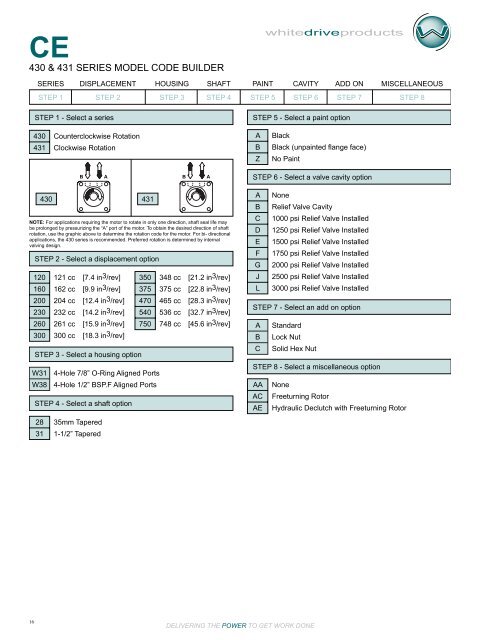
<strong>CE</strong><br />
430 & 431 SERIES mOdEL COdE BUILdER<br />
16<br />
DELIVERING THE POWER TO GET WORK DONE<br />
whitedriveproducts<br />
SERIES DISPLA<strong>CE</strong>MENT HOUSING SHAFT PAINT CAVITY ADD ON MIS<strong>CE</strong>LLANEOUS<br />
STEP 1 STEP 2 STEP 3 STEP 4 STEP 5 STEP 6 STEP 7 STEP 8<br />
STEP 1 - Select a series<br />
430<br />
431<br />
Counterclockwise Rotation<br />
Clockwise Rotation<br />
STEP 2 - Select a displacement option<br />
120<br />
160<br />
200<br />
230<br />
260<br />
300<br />
STEP 3 - Select a housing option<br />
W31<br />
W38<br />
121 cc [7.4 in3/rev]<br />
162 cc [9.9 in3/rev]<br />
204 cc [12.4 in3/rev]<br />
232 cc [14.2 in3/rev]<br />
261 cc [15.9 in3/rev]<br />
300 cc [18.3 in3/rev]<br />
350<br />
375<br />
470<br />
540<br />
750<br />
4-Hole 7/8” O-Ring Aligned Ports<br />
4-Hole 1/2” BSP.F Aligned Ports<br />
STEP 4 - Select a shaft option<br />
28<br />
31<br />
430 431<br />
NOTE: For applications requiring the motor to rotate in only one direction, shaft seal life may<br />
be prolonged by pressurizing the “A” port of the motor. To obtain the desired direction of shaft<br />
rotation, use the graphic above to determine the rotation code for the motor. For bi- directional<br />
applications, the 430 series is recommended. Preferred rotation is determined by internal<br />
valving design.<br />
35mm Tapered<br />
1-1/2” Tapered<br />
348 cc [21.2 in3/rev]<br />
375 cc [22.8 in3/rev]<br />
465 cc [28.3 in3/rev]<br />
536 cc [32.7 in3/rev]<br />
748 cc [45.6 in3/rev]<br />
STEP 5 - Select a paint option<br />
A<br />
B<br />
Z<br />
Black<br />
Black (unpainted flange face)<br />
No Paint<br />
B A<br />
B A<br />
STEP 6 - Select a valve cavity option<br />
A<br />
B<br />
C<br />
D<br />
E<br />
F<br />
G<br />
J<br />
L<br />
STEP 7 - Select an add on option<br />
A<br />
B<br />
C<br />
Standard<br />
Lock Nut<br />
Solid Hex Nut<br />
STEP 8 - Select a miscellaneous option<br />
AA<br />
AC<br />
AE<br />
None<br />
Relief Valve Cavity<br />
1000 psi Relief Valve Installed<br />
1250 psi Relief Valve Installed<br />
1500 psi Relief Valve Installed<br />
1750 psi Relief Valve Installed<br />
2000 psi Relief Valve Installed<br />
2500 psi Relief Valve Installed<br />
3000 psi Relief Valve Installed<br />
None<br />
Freeturning Rotor<br />
Hydraulic Declutch with Freeturning Rotor