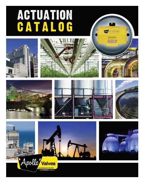
Apollo Valves - Actuator Control - Wainbee Limited
Apollo Valves - Actuator Control - Wainbee Limited
Apollo Valves - Actuator Control - Wainbee Limited
- No tags were found...
Create successful ePaper yourself
Turn your PDF publications into a flip-book with our unique Google optimized e-Paper software.
<strong>Actuator</strong>s and <strong>Control</strong>sACTUATORSINDEXPAGEI) Pneumatic <strong>Actuator</strong>s . . . . . . . . . . . . . . . . . . . . . . . . . . . . . . . . . . . . . . . . . . . . . . . . . . . . . . . . . 3-21<strong>Apollo</strong> ® Pneumatic Rack and Pinion <strong>Actuator</strong>s . . . . . . . . . . . . . . . . . . . . . . . . . . . . . . . . . 3-10<strong>Apollo</strong> ® <strong>Actuator</strong> Parts List Model A0025-A1600. . . . . . . . . . . . . . . . . . . . . . . . . . . . . . . . . . . 4<strong>Apollo</strong> ® <strong>Actuator</strong> Parts List Model A2500-A4000. . . . . . . . . . . . . . . . . . . . . . . . . . . . . . . . . . . 5<strong>Apollo</strong> ® <strong>Actuator</strong> Dimensions Models A0025-A4000 . . . . . . . . . . . . . . . . . . . . . . . . . . . . . . 6-7<strong>Apollo</strong> ® <strong>Actuator</strong> Dimensions Model 32 . . . . . . . . . . . . . . . . . . . . . . . . . . . . . . . . . . . . . . . . . . 8<strong>Apollo</strong> ® Double Acting Torque . . . . . . . . . . . . . . . . . . . . . . . . . . . . . . . . . . . . . . . . . . . . . . . . . . 8<strong>Apollo</strong> ® Spring Return Torque. . . . . . . . . . . . . . . . . . . . . . . . . . . . . . . . . . . . . . . . . . . . . . . . . . 9<strong>Apollo</strong> ® <strong>Actuator</strong> Technical Data . . . . . . . . . . . . . . . . . . . . . . . . . . . . . . . . . . . . . . . . . . . . . . . 10<strong>Apollo</strong> ® Acutorque SS <strong>Actuator</strong>s. . . . . . . . . . . . . . . . . . . . . . . . . . . . . . . . . . . . . . . . . . . . 11-16G Series <strong>Actuator</strong>s. . . . . . . . . . . . . . . . . . . . . . . . . . . . . . . . . . . . . . . . . . . . . . . . . . . . . . . 17-21II) Electric <strong>Actuator</strong>s. . . . . . . . . . . . . . . . . . . . . . . . . . . . . . . . . . . . . . . . . . . . . . . . . . . . . . . . 22-30AE <strong>Actuator</strong> . . . . . . . . . . . . . . . . . . . . . . . . . . . . . . . . . . . . . . . . . . . . . . . . . . . . . . . . . . . . 22-25AE <strong>Actuator</strong> Wiring Diagram. . . . . . . . . . . . . . . . . . . . . . . . . . . . . . . . . . . . . . . . . . . . . . . . . . 25CS and CL Electric <strong>Actuator</strong>s . . . . . . . . . . . . . . . . . . . . . . . . . . . . . . . . . . . . . . . . . . . . . . 26-27LB Series Electric <strong>Actuator</strong>s . . . . . . . . . . . . . . . . . . . . . . . . . . . . . . . . . . . . . . . . . . . . . . . 28-30III) Accessories . . . . . . . . . . . . . . . . . . . . . . . . . . . . . . . . . . . . . . . . . . . . . . . . . . . . . . . . . . . . 31-38<strong>Apollo</strong> ® Solenoids. . . . . . . . . . . . . . . . . . . . . . . . . . . . . . . . . . . . . . . . . . . . . . . . . . . . . . . . 31-32Stonel Limit Switch Assemblies . . . . . . . . . . . . . . . . . . . . . . . . . . . . . . . . . . . . . . . . . . . . . . . 33VRC Positioners . . . . . . . . . . . . . . . . . . . . . . . . . . . . . . . . . . . . . . . . . . . . . . . . . . . . . . . . . . . 34PMV Positioners. . . . . . . . . . . . . . . . . . . . . . . . . . . . . . . . . . . . . . . . . . . . . . . . . . . . . . . . . 35-36Proximity Valve Position Monitoring Systems . . . . . . . . . . . . . . . . . . . . . . . . . . . . . . . . . . . . 37OSHA Lockout Tagout Device . . . . . . . . . . . . . . . . . . . . . . . . . . . . . . . . . . . . . . . . . . . . . . . . 38IV) <strong>Apollo</strong> ® Ball Valve Information . . . . . . . . . . . . . . . . . . . . . . . . . . . . . . . . . . . . . . . . . . . . . . 39-44V) <strong>Apollo</strong> ® Butterfly <strong>Valves</strong> . . . . . . . . . . . . . . . . . . . . . . . . . . . . . . . . . . . . . . . . . . . . . . . . . . . 45-46NOTES . . . . . . . . . . . . . . . . . . . . . . . . . . . . . . . . . . . . . . . . . . . . . . . . . . . . . . . . . . . . . . . . . . . . . . . 47GENERAL INFORMATION2Conbraco Industries, Inc. certifies that the published torque values are the minimum values to be expected froma new actuator. A properly applied and maintained actuator should produce the published torque valuesthroughout its service life. Conbraco Industries Inc. reserves the right without notice to alter designs, specificationsor availability of the products described herein. Mounting brackets should only be made from certified dimensionaldrawings.CONBRACO INDUSTRIES STATEMENT OF WARRANTY ANDLIMITATIONS OF LIABILITYConbraco Industries, Inc. warrants, to its initial purchaseronly, that its products which are delivered to thisinitial purchaser will be of the kind described in theorder or price list and will be free of defects in workmanshipor material for a period of TWO years from thedate of delivery to you, our initial purchaser.Should any failure to conform to this warranty appearwithin two years after the date of the initial delivery toour initial purchaser, Conbraco will, upon written notificationthereof and substantiation that the goods havebeen stored, installed, maintained and operated in accordancewith Conbraco's recommendations and standardindustry practice, correct such defects by suitablerepair or replacement at Conbraco's own expense.New For April 2009: Extension of Warrantyfor <strong>Apollo</strong> products manufactured in theUSA. Conbraco warrants those products that aremanufactured in our USA facilities for an additional 3years; making the total warranty FIVE years. This extendedwarranty applies to <strong>Apollo</strong> brand productwith”Made in the USA” markings only.THIS WARRANTY IS EXCLUSIVE AND IS IN LIEU OFANY IMPLIED WARRANTY OF MERCHANTABILITY, FIT-NESS FOR A PARTICULAR PURPOSE OR OTHERWARRANTY OF QUALITY, WHETHER EXPRESSED ORIMPLIED, EXCEPT THE WARRANTY OF TITLE ANDAGAINST PATENT INFRINGEMENT. Correction of nonconformities,in the manner and for the period of timeprovided above, shall constitute fulfillment of allliabilities of Conbraco to our initial purchaser, with respectto the goods, whether based on contract, negligence,strict tort or otherwise. It is the intention ofConbraco Industries, Inc. that no warranty of any kind,whether expressed or implied shall pass through ourinitial purchaser to any other person or corporation.LIMITATION OF LIABILITY: Conbraco Industries, inc.SHALL NOT UNDER ANY CIRCUMSTANCES BE LIABLEFOR SPECIAL OR CONSEQUENTIAL DAMAGES SUCHAS, BUT NOT LIMITED TO, DAMAGES OR TO LOSS OFOTHER PROPERTY OR EQUIPMENT, LOSS OF PROFITSOR REVENUE, COST OF CAPITAL, COST OF PUR-CHASED OR REPLACEMENT GOODS, OR CLAIMS OFCUSTOMERS OF OUR INITIAL PURCHASER. THEREMEDIES OF OUR INITIAL PURCHASER, AND ALLOTHERS, SET FORTH HEREIN, ARE EXCLUSIVE, ANDTHE LIABILITY OF CONBRACO WITH RESPECT TOSAME SHALL NOT, EXCEPT AS EXPRESSLY PROVIDEDHEREIN, EXCEED THE PRICE OF THE GOODS UPONWHICH SUCH LIABILITY IS BASED.
<strong>Actuator</strong>s and <strong>Control</strong>sA2500 to A4000Parts List01 (1) Body 10* (1) Upper Bearing 21* (1) Thrust Washer02 (2) Piston 14* (2) Piston Guide 23 (2 or 4) Rack Capscrew03 (2) D-A End Cap 15* (2) Heel Guide 24 (8 or 20) DA End Cap Bolt04 (2) S-R End Cap 16* (2) Piston O-ring 25 (8 or 20) SR End Cap Bolt05 (1) Pinion 17* (2) End Cap O-ring 26 (2) Port O-ring06 (2) Gear Rack 18* (1) Lower Pinion O-ring08 (0 to 14) Coil Spring 19* (1) Upper Pinion O-ring09* (1) Lower Bearing 20* (1) Spring Clip* Contained in Repair Kit5
<strong>Actuator</strong>s and <strong>Control</strong>sDimensionalDataRack & Pinion <strong>Actuator</strong> Envelop DimensionsOverall Overall Body Body Solenoid Port Adjustable Adjustable Stop Stop(Inches) Length Length Height Width Pad Offset Location Closed Stop Closed Stop Size ProtrusionA (DA) B (SR) C H I J J1* L* Y* X max.*A0025 6.26 6.77 3.15 2.91 1.81 1.26 1.11 0.45 1/4”-20 1.63A0040 7.09 8.03 3.66 3.39 2.09 1.32 1.38 0.61 5/16”-18 1.91A0065 7.83 9.80 4.13 3.86 2.26 1.54 1.57 0.61 5/16”-18 1.91A0100 8.70 10.51 4.65 4.25 2.48 1.59 1.72 0.73 3/8”-16 2.30A0150 10.00 12.20 5.51 4.76 2.76 1.59 1.92 0.97 3/8”-16 2.64A0200 11.40 14.17 5.63 5.04 2.87 1.99 2.12 0.97 1/2”-13 2.91A0350 12.01 15.24 7.13 6.81 3.71 2.85 2.85 0.97 1/2”-13 3.31A0600 15.24 18.78 8.66 8.15 4.45 3.33 3.50 1.63 5/8”-11 4.51A0950 16.69 20.35 10.20 9.09 4.96 4.15 4.03 1.63 5/8”-11 4.51A1600 20.31 25.08 11.69 10.43 5.59 4.74 4.50 1.87 3/4”-10 4.88A2500 14.88 22.40 14.02 13.78 7.28 7.01 N/A N/A N/A N/AA4000 19.76 32.83 14.96 14.96 7.87 7.48 N/A N/A N/A N/A6*Applies to double stop versions only
<strong>Actuator</strong>s and <strong>Control</strong>sDimensionalDataRack & Pinion <strong>Actuator</strong> Drive DetailsBottom Valve Insert or Standard Standard Across(Inches) Pinion Stem Adapter Pinion Square Square CornersDiameter Clearance Height Recess Output Output DiameterK M1 M3 N O max O min P1A0025 0.94 1.36 0.67 0.04 0.437 0.433 0.555A0040 1.30 1.36 0.67 0.04 0.555 0.551 0.713A0065 1.30 1.36 0.67 0.04 0.556 0.551 0.713A0100 1.50 1.36 0.79 0.06 0.753 0.748 0.992A0150 2.17 1.97 0.79 0.04 0.753 0.748 1.004A0200 2.17 1.97 1.16 0.06 0.871 0.866 1.100A0350 2.17 1.97 1.16 0.06 1.068 1.063 1.425A0600 2.68 2.05 1.16 0.06 1.068 1.063 1.425A0950 2.95 2.52 1.95 0.06 1.424 1.417 1.898A1600 3.74 3.23 2.30 0.06 1.817 1.811 2.370A2500 3.35 2.60 N/A 0.12 1.817 1.811 2.370A4000 4.72 3.03 N/A 0.06 2.173 2.165 2.843Rack & Pinion <strong>Actuator</strong> Mounting DimensionsPrimary Primary Secondary(Inches) ISO “F” Bolt Primary ISO “F” Secondary SecondaryPattern Circle Fastener Pattern Bolt Circle FastenerV W V1 W1A0025 F04 1.65 1/4”-20 x .39” N/A N/A N/AA0040 F05 1.969 1/4”-20 x .39” F07 2.756 5/16”-18 x .39A0065 F05 1.969 1/4”-20 x .39” F07 2.756 5/16”-18 x .39A0100 F05 1.969 1/4”-20 x .39” F07 2.756 5/16”-18 x .39A0150 F07 2.756 5/16”-18 x .39 F10 4.016 3/8”-16 x .63”A0200 F07 2.756 5/16”-18 x .39 F10 4.016 3/8”-16 x .63”A0350 F07 2.756 5/16”-18 x .39 F10 4.016 3/8”-16 x .63”A0600 F10 4.016 3/8”-16 x .63” F12 4.921 1/2”-13 x .79”A0950 F10 4.016 3/8”-16 x .63” F14 5.512 5/8”-11 x .98”A1600 F16 6.496 3/4”-10 x 1.14” N/A N/A N/AA2500 F16 6.496 3/4”-10 x 1.14” N/A N/A N/AA4000 F16 6.496 3/4”-10 x 1.14” F25 10.000 5/8”-11 x .98”Rack & Pinion <strong>Actuator</strong> Mounting DetailsNamur Namur Thrust Namur(Inches) Shaft Shaft Bearing Namur Shaft Flat Namur Bolt Namur BoltExtension Diameter Diameter Flats Length Pattern PatternD E E2 F G T1 U1A0025 0.79 0.63 0.91 0.39 0.47 3.15 1.181A0040 0.79 0.87 1.18 0.55 0.47 3.150 1.181A0065 0.79 0.87 1.18 0.55 0.47 3.150 1.181A0100 0.79 0.87 1.18 0.55 0.47 3.150 1.181A0150 0.79 1.42 1.77 0.75 0.47 3.150 1.181A0200 0.79 1.42 1.77 0.75 0.47 3.150 1.181A0350 0.79 1.42 1.77 0.75 0.47 3.150 1.181A0600 1.18 2.17 2.56 1.42 0.39 5.118 1.181A0950 1.18 2.17 2.56 1.42 0.39 5.118 1.181A1600 1.18 2.52 2.95 1.42 039 5.118 1.181A2500 1.18 2.17 2.56 1.42 0.39 5.118 1.181A4000 1.18 2.52 3.15 1.42 0.39 5.118 1.1817
<strong>Actuator</strong>s and <strong>Control</strong>sDimensionsModel32Torque Output (in-lb)ModelSupply Pressure (psi)40 50 60 70 80 90 100 115DA32 34 43 55 64 71 82 87 101Double Acting<strong>Actuator</strong>8Sizing <strong>Apollo</strong> ® Rack & PinionTorque Output of Double Acting <strong>Actuator</strong>s (in-lb)<strong>Actuator</strong>SizeSupply Pressure (psi)40 45 50 55 60 70 75 80 90 100 120AD0012 58.9 66.4 73.9 81.4 88.9 104 111 119 134 149 179AD0025 109 123 137 151 165 193 206 220 248 276 332AD0040 205 231 257 283 309 361 387 413 466 518 622AD0065 312 352 392 431 471 551 590 630 709 789 948AD0100 461 520 578 637 696 813 872 930 1048 1165 1400AD0150 739 833 927 1021 1115 1303 1397 1491 1680 1868 2244AD0200 1011 1140 1269 1398 1527 1784 1913 2042 2299 2557 3072AD0350 1757 1981 2205 2428 2652 3100 3323 3547 3994 4442 5337AD0600 2986 3366 3747 4127 4507 5267 5647 6028 6788 7548 9069AD0950 4458 5025 5593 6160 6728 7862 8430 8997 10132 11267 13537AD1600 7369 8307 9245 10183 11121 12998 13936 14874 16750 18626 22379AD2500 11825 13270 14768 16267 17847 20858 22363 23869 26880 29891 35912AD4000 19962 22495 25035 27576 30127 35210 37751 40293 45375 50458 60623
<strong>Actuator</strong>s and <strong>Control</strong>s<strong>Actuator</strong>SizeSpring SetSpring StrokeTorque Output of Spring Return <strong>Actuator</strong>s (in-lb)Air StrokeSupply Pressure (psi)40 60 80 100 120Start End Start End Start End Start End Start End Start EndAS0012 2 63 40 - - 48 24 80 55 111 87 143 1192 62 39 74 44 130 103 189 162 248 221 306 2803 94 59 48 8 107 67 166 126 225 185 284 244AS0025 4 125 78 - - 85 31 144 90 203 149 262 2085 156 98 - - - - 121 54 180 113 239 1726 188 117 - - - - 99 18 158 77 217 1362 117 73 133 82 243 193 354 303 464 414 575 5243 176 110 91 15 201 125 312 236 422 346 533 457AS0040 4 234 146 - - 159 58 270 169 380 279 491 3905 293 183 - - - - 228 101 338 212 449 3226 351 220 - - - - 185 34 296 144 406 2552 186 117 196 117 365 285 533 454 701 622 870 7903 279 176 129 10 297 178 466 347 634 515 802 683AS0065 4 372 234 - - 230 71 398 240 567 408 735 5765 465 292 - - - - 331 133 500 301 668 4706 558 351 - - - - 264 26 432 194 601 3632 258 161 303 192 552 441 801 690 1050 939 1299 11883 387 242 211 44 460 293 709 542 958 791 1206 1039AS0100 4 516 323 - - 367 144 616 393 865 642 1114 8915 646 403 - - - - 523 245 772 494 1021 7436 775 484 - - - - 430 96 679 345 928 5942 423 259 485 297 884 696 1283 1094 1681 1493 2080 18923 634 388 337 54 735 453 1134 852 1533 1250 1931 1649AS0150 4 845 517 - - 587 210 985 609 1384 1007 1783 14065 1056 647 - - - - 837 366 1235 764 1634 11636 1268 776 - - - - 688 123 1087 522 1485 9202 579 362 656 406 1202 952 1747 1498 2293 2043 2838 25893 868 542 448 74 994 619 1539 1165 2085 1710 2631 2256AS0200 4 1158 723 - - 786 287 1332 832 1877 1378 2423 19245 1447 904 - - - - 1124 500 1669 1045 2215 15916 1736 1085 - - - - 916 167 1462 713 2007 12582 1025 658 1105 684 2053 1632 3001 2580 3949 3528 4897 44763 1537 987 727 95 1675 1043 2623 1991 3571 2939 4519 3887AS0350 4 2049 1317 - - 1297 455 2245 1403 3193 2351 4141 32995 2561 1646 - - - - 1866 814 2814 1762 3762 27106 3074 1975 - - - - 1488 225 2436 1173 3384 21212 1723 1082 1920 1183 3531 2794 5142 4405 6753 6016 8364 76283 2585 1624 1298 193 2909 1804 4520 3415 6131 5026 7742 6637AS0600 4 3446 2165 - - 2287 814 3898 2425 5509 4036 7120 56475 4308 2706 - - - - 3276 1434 4887 3046 6498 46576 5169 3247 - - - - 2654 444 4265 2055 5876 36662 2563 1587 2898 1777 5303 4182 7708 6587 10113 8992 12518 113973 3844 2381 1986 304 4391 2709 6796 5114 9201 7519 11606 9924AS0950 4 5125 3175 - - 3479 1236 5884 3641 8288 6046 10693 84515 6407 3968 - - - - 4971 2168 7376 4573 9781 69786 7688 4762 - - - - 4059 695 6464 3100 8869 55052 4193 2646 4765 2988 8741 6964 12716 10939 16692 14915 20668 188903 6289 3970 3244 578 7220 4554 11196 8530 15171 12505 19147 16481AS1600 4 8385 5293 - - 5699 2145 9675 6120 13650 10096 17626 140715 10481 6616 - - - - 8154 3711 12129 7686 16105 116626 12578 7939 - - - - 6633 1301 10608 5277 14584 92526 7013 4401 6881 4278 12875 10273 18869 16267 24863 22261 30858 282558 9351 5868 5251 1781 11245 7775 17239 13769 23233 19764 29228 25758AS2500 10 11689 7335 - - 9615 5278 15609 11272 21603 17266 27597 2326012 14026 8803 - - 7985 2780 13979 8774 19973 14768 25967 2076314 16364 10270 - - - - 12349 6277 18343 12271 24337 182656 11835 7429 11701 7310 21862 17472 32024 27633 42185 37795 52347 479568 15780 9905 8949 3096 19111 13257 29272 23419 39434 33580 49595 43742AS4000 10 19725 12381 - - 16359 9042 26521 19204 36682 29365 46844 3952712 23670 14857 - - 13608 4828 23770 14989 33931 25150 44093 3531214 27615 17333 - - - - 21018 10774 31180 20936 41341 310979
<strong>Actuator</strong>s and <strong>Control</strong>sTechnical DataDouble ActingAD0012 AD0025 AD0040 AD0065 AD0100 AD0150 AD0200 AD0350 AD0600 AD0950 AD1600 AD2500 AD4000Weight (lbs) 1.3 2.9 4.0 5.3 6.8 10.5 12.8 23.0 43.0 58.0 95.0 125.0 191.0Spring ReturnAS0012 AS0025 AS0040 AS0065 AS0100 AS0150 AS0200 AS0350 AS0600 AS0950 AS1600 AS2500 AS4000Weight (lbs) 1.5 3.7 5.3 7.9 10.1 15.2 20.1 37.0 61.0 85.0 145.0 194.0 291.0Displacement (cu in.) AD0012 AD0025 AD0040 AD0065 AD0100 AD0150 AD0200 AD0350 AD0600 AD0950 AD1600 AD2500 AD4000AS0012 AS0025 AS0040 AS0065 AS0100 AS0150 AS0200 AS0350 AS0600 AS0950 AS1600 AS2500 AS4000Port A CCW 3.1 6.1 9.8 20 21 45 49 110 177 287 445 488 824Port B CW 3.7 6.7 13 22 30 40 61 116 189 299 488 568 1068Air consumption (scf per 90°) = (Displacement/1728)*(Supply Pressure + 14.7)/14.7Operating TimeAD0012 AD0025 AD0040 AD0065 AD0100 AD0150 AD0200 AD0350 AD0600 AD0950 AD1600 AD2500 AD4000AS0012 AS0025 AS0040 AS0065 AS0100 AS0150 AS0200 AS0350 AS0600 AS0950 AS1600 AS2500 AS4000Seconds 0.4 0.5 0.7 1.1 1.2 1.8 2.3 3.6 4.5 5.4 6.9 7 12Selecting/Sizing <strong>Apollo</strong> Rack & Pinion <strong>Actuator</strong>sEstablish the valve operating torque beginning with the torque constants for the appropriate pressure and valve as found on pages 41 or 42. Usethe torque adjustment factors found on page 43 to arrive at an in-service torque figure. Multiple adjustment factors may be required. Do not forgetto include adjustments for graphite stem packings (valve options -21, 24 or 65 for conventional ball valves, BO, BS, EV, FD and FP for TEVs’)For Double Acting <strong>Actuator</strong>sBased on the available air supply select an actuator with torque outputs that exceed the in-service torque by at least 10%.For Spring Return <strong>Actuator</strong>sConsidering the available air supply, select an actuator where both the Spring-Ending torque figure and the Air-Ending torque figure exceeds thein-service torque by at least 10%.Note: Single-Stop actuators are appropriate for use on ball valves. Dual-Stop actuators are required for most butterfly valve applications with afew exceptions but may also be used on ball valves.<strong>Apollo</strong> ® Pneumatic <strong>Actuator</strong> Numbering SystemA X - X X X X - X - X X - X - XACTIOND - Double ActiongS - Spring ReturnK - KitSIZE0012*00250040006501000150020003500600095016002500*4000*SEAL OPTIONN - Nitrile (Normal temprange, -4° to 175°F)H - Fluorocarbon (Hightemp range, -4° to250°F)L - Silicone (Low temprange, -40° to 175°F)SPRING SET00 (DA)0102030405060708101214LIMIT STOP0- None** (Std. onsizes 0012,2500, & 4000)1 -Single AdjustableLimit Stop (Forsizes 0025 thru1600 only)2 -Dual AdjustableLimit Stops (Forsizes 0025 thru1600 only)INSERTA - STDB - Without* Units with no adapters option** Optional double stroke adjustment plate is availablefor 2500 & 4000 (see price list)NOTE: Add suffix “F” for fail open units10
<strong>Actuator</strong>s and <strong>Control</strong>s“Acutorque”Stainless Steel<strong>Actuator</strong>Design andConstruction7593a6241103b1. Investment Cast BodyAssures manufacturing of other special alloys, such as Monel2. Unique Drive PinionOne piece stainless steel alloy shaft, precision machined gearand teeth for precise control3. BearingsReplaceable top and bottom TFE Pinion Bearings to ensure lowfriction, stability above 400°F, and chemical resistance4. Travel StopsProvides +/-4° travel adjustment in outboard direction5. Accessory MountingManufactured to NAMUR to provide international standardizedmounting6. Stainless Steel PistonsPrecision cast pistons are guided through full face engagementwith the pinion and piston guide7. NAMUR Slotted ShaftStandard to provide a self-centering positive drive forpositioners, a variety of switches8. <strong>Actuator</strong> MountingManufactured in accordance with ISO 5211 to ensuremounting the actuator directly on valves9. Pre-loaded CartridgesConverts a standard double acting actuator to a springreturn unit by simply removing the end caps and addingthe spring cartridges10. NAMUR Solenoid MountingInternational standard for direct mounting of solenoidvalves11
<strong>Actuator</strong>s and <strong>Control</strong>sOperationThe <strong>Apollo</strong> ® Acutorque actuator is manufactured with an integraland internal air manifold. The solenoid mounting pad ismanufactured to Namur dimensional standards as to allow forthe direct mounting of various manufacturers’ solenoid valvesand other flow control devices. For applications not requiringa direct mount solenoid valve, ports are tapped to NPT standards(American National Standard taper threads).Reverse RotationWhen required, a clockwise rotation of the drive pinion, bymeans of air to PORT A can be achieved by reversing the pistonsinside the actuator body (rotate 180 degrees).Spring ConfigurationEach Acutorque actuator comes with a complete spring pack(6 springs per side with nylon retainers) unless otherwisespecified. When less than the full spring pack is desired forvarious torque outputs (see torque chart); springs can be removedfrom the actuator end caps. It is very important thatsprings can be arranged in a symmetrical manner (positionedas shown below) so that unwarranted side-load does notoccur between the pistons and actuator body. CAUTION:Refer to operation and maintenance instructions beforedisassembly and removal of springs.Air to PORT A - Pressure applied enters center ofchamber forcing the pistons outward and rotating thedrive pinion in a counter-clockwise direction and forcingexhaust air out of PORT B.Air to PORT B - Air pressure enters the outer chambersforcing the pistons inward and rotating the drive pinionin a clockwise direction while forcing exhaust air out ofPORT A.Loss of air pressure in the center chamber allows energyin the compressed springs to force the pistons inward,resulting in a clockwise rotation of the drive pinionwhile exhaust air leaves via PORT A.12
<strong>Actuator</strong>s and <strong>Control</strong>sFeaturesCorrosion ResistanceAll metal components are cast or machined from Stainless Steelor Monel, which offers excellent resistance to most corrosivechemicals as well as industrial atmospheres.No LubricationAll actuators are factory lubricated for the optimum life of the actuatorunder normal conditions. Teflon ® piston bearings are usedbecause of their self-lubricating properties.Simple MaintenanceEach actuator is designed for ease of maintenance. Should youwish simply to change a spring rating or completely rebuild aunit, total disassembly and reassembly is easily performed injust minutes with standard shop tools.ISO/NAMUR MountingBy using ISO/NAMUR standards, our actuators lend themselvesto a host of various manufacturers’ direct mount accessories.Solenoid valves, limit switches, positioners, etc. bolt directly tothe actuator and in turn reduces the cost of assembly and installationof automated packages. Flexibility for future system modificationsis greatly enhanced.QualityEach part of the actuator must pass a stringent quality test beforeit can be incorporated into an assembly. All materials usedin construction must be certified and tested to prove theirproper composition. Every cast part must pass an X-ray testbefore proceeding to the machining process. After machiningevery part is dimensionally calibrated in order to assure itmeets acceptable tolerance.SafetyAll actuator bodies and end caps are investment cast stainlesssteel, rugged and built to last. It may be argued that the mechanicalproperties of stainless steel permit the ability to usethis wall tubing in the construction of an actuator. However,that is not the case with our actuator. Thick wall castings meanprotection for actuator internal porting and components as wellas maintenance and operating personnel. Our unique drivepinion design ensures blowout proof protection. Spring retainersare incorporated to allow safe removal of end caps duringspring torque rating change or rebuild process.P/N DESCRIPTION QTY MATERIAL P/N DESCRIPTION QTY MATERIAL1 Body 1 304 Stainless Steel 16 O-Ring-End Cap 2 Nitrile2 Piston 2 303 Stainless Steel 17a Bolts-End Cap 8 Stainless Steel3 End Caps-Double Acting 2 Stainless Steel 17b Spring Bearing 8 Stainless Steel4 Drive Pinion 1 17-4 Stainless Steel 18 Adjusting Travel Stop 2 Stainless Steel5 Guide Bearing Plate 2 Nylon 6 19 O-Ring-Travel Stop 2 Nitrile6 Pinion Bearing Top 1 Teflon 20a Washer 2 Stainless Steel7 Pinion Bearing Bottom 1 Teflon 20b Nut-Travel Stop 2 Stainless Steel8 Snap Ring 1 Stainless Steel 21 End Nut-Travel 2 Stainless Steel9 O-Ring-Inner Top 1 Viton 22 Spring Retainer (S) * Nylon 610 O-Ring-Outer Top 1 Viton 23 Spring Retainer (L) * Nylon 611a Washer 1 Stainless Steel 24 Spring * Plated CS11b Bearing 1 Nylon 6 25 Spring Screw * Stainless Steel12 O-Ring-Inner Bottom 1 Viton 26 Spring Nut * Stainless Steel13 O-Ringer-Outer Bottom 1 Viton 27 Positioner Indicator 1 Nylon14 O-Ring-Piston 2 Viton 28 Plug 2 Nylon 615 Bearing-Piston 2 Nylon 6Grade of Stainless SteelBody & End Caps 304Shaft17-4 phPiston 303Bolts 18-813
<strong>Actuator</strong>s and <strong>Control</strong>sDimensionalDataMounting DimensionsMODEL R S T V W X Y Z AA BB CC DD EE FF GG HH3SD045003SS04560mm 24 1/4"NPT M5 11 15 M5 8 42 M5 6 30 80 88.9 31.75 M5 8in 0.95 1/4"NPT M5 0.4 0.59 M5 0.31 1.65 M5 0.24 1.18 3.15 3.5 1.25 M5 0.313SD060003SS060603SD085003SS085603SD105003SS105603SD125003SS125603SD140003SS140603SD170003SS170603SD210003SS21060mm 24 1/4"NPT M5 14 15 M6 8 50 M5 6 30 80 88.9 31.75 M6 8in 0.95 1/4"NPT M5 0.55 0.59 M6 0.31 1.97 M5 0.24 1.18 3.15 3.5 1.25 M6 0.31mm 24 1/4"NPT M5 19 17 M8 12 70 M5 6 30 80 114 38 M8 12in 0.95 1/4"NPT M5 0.75 0.68 M8 0.47 2.75 M5 0.24 1.18 3.15 4.5 1.5 M8 0.47mm 24 1/4"NPT M5 19 20 M8 12 70 M5 6 30 80 114 38 M8 12in 0.95 1/4"NPT M5 0.75 0.79 M8 0.47 2.75 M5 0.24 1.18 3.15 4.5 1.5 M8 0.47mm 24 1/4"NPT M5 22 30 M8 18 102 M5 8 30 130 NA 50.8 NA NAin 0.95 1/4"NPT M5 0.87 1.2 M8 0.71 4.02 M5 0.31 1.18 5.12 2mm 24 1/4"NPT M5 22 27 M10 18 102 M5 8 30 130 NA 50.8 NA NAin 0.95 1/4"NPT M5 0.87 1.06 M10 0.71 4.02 M5 0.31 1.18 5.12 2mm 24 1/4"NPT M5 32 36 M12 24 125 M5 8 30 130 NA 76 NA NAin 0.95 1/4"NPT M5 1.26 1.42 M12 0.95 4.92 M5 0.31 1.18 5.12 3mm 24 1/4"NPT M5 36 43 M20 28 140 M5 8 30 130 NA 76 NA NAin 0.95 1/4"NPT M5 1.42 1.69 M20 1.1 5.51 M5 0.31 1.18 5.12 314
<strong>Actuator</strong>s and <strong>Control</strong>sDouble ActingTorqueACTUATORSIZE3SD045003SD060003SD085003SD10500TORQUE (INCH/LBS) VS. AIR SUPPLY PRESSURE (PSI)40 60 80 100 120 15074 116 152 199 239 289151 234 328 413 499 600365 548 732 915 1097 1315701 1068 1436 1829 2184 2632ACTUATORSIZE3SD125003SD140003SD170003SD21000TORQUE (INCH/LBS) VS. AIR SUPPLY PRESSURE (PSI)40 60 80 100 120 1501355 2069 2759 3449 4115 51682018 3032 4039 5046 6056 66152868 4050 5324 6640 7987 100425328 8462 11188 13884 16709 20929General DimensionsMODEL AS C D E F G H J K L N M Q3SD045003SS04560mm 168 65 52.5 62.5 35 16 4 20 10 12 16 23 32in 6.61 2.56 2.07 2.46 1.38 0.63 0.16 0.79 0.39 0.47 0.63 0.91 1.263SD060003SS060603SD085003SS085603SD105003SS105603SD125003SS125603SD140003SS140603SD170003SS170603SD210003SS21060mm 180 81 60.5 74 39 16 4 20 10 12 16 23 32in 7.09 3.19 2.38 2.91 1.54 0.63 0.16 0.79 0.39 0.47 0.63 0.91 1.26mm 222 108 74 100.5 52 16 4 20 10 12 16 24 32in 8.74 4.25 2.91 3.96 2.05 0.63 0.16 0.79 0.39 0.47 0.63 0.95 1.26mm 290 133 86.5 117 58.5 16 4 20 10 12 16 30 32in 11.42 5.24 3.41 4.61 2.3 0.63 0.16 0.79 0.39 0.47 0.63 1.18 1.26mm 390 155 110.2 136 68 20 4 30.5 10.5 12 16 40 32in 15.5 5.02 3.59 5.65 2.91 0.79 0.16 1.2 0.41 0.47 0.63 1.57 1.26mm 420 176 116.5 156 79 20 4 30.5 10.5 12 16 40 32in 16.54 6.93 4.59 6.14 3.11 0.79 0.16 1.2 0.41 0.47 0.63 1.57 1.26mm 538 210 131.5 193 98 20 4 30.5 10.5 12 16 50 32in 21.18 8.27 5.18 7.6 3.86 0.79 0.16 1.2 0.41 0.47 0.63 1.97 1.26mm 698 258 156 236 120 32 4 30.5 10.5 12 16 68 32in 27.48 10.16 6.14 9.29 4.72 1.26 0.16 1.2 0.41 0.47 0.63 2.68 1.2615
<strong>Actuator</strong>s and <strong>Control</strong>sSpring ReturnTorqueSupply Pressurein PSITORQUE (INCH/LBS) VS. AIR SUPPLY PRESSURE (PSI)ACTUATOR SPRING SET#* 40 60 80 100 120 150 SPRINGSIZESTROKE0 90 0 90 0 90 0 90 0 90 0 90 90 03SS045X02345656 43 98 84 136 121 178 162 220 203 256 230 34 2145 24 88 65 126 93 165 142 204 179 238 204 49 2972 42 115 90 154 126 196 163 218 175 71 43109 76 147 109 182 184 209 156 88 5297 58 135 91 172 103 190 129 107 643SS060X03SS085X03SS105X03SS125X03SS140X03SS170X03SS210X023456234562345623456234562345623456101 79 167 140 237 214 304 278 369 345 435 399 61 3784 48 147 107 219 185 284 248 352 315 405 350 93 55129 77 203 157 268 219 331 276 380 315 124 75110 45 187 131 250 189 315 250 359 272 156 93171 102 233 158 296 218 335 228 186 112275 206 450 369 645 572 821 744 999 919 1175 1065 172 93236 126 403 281 602 493 773 661 949 884 1105 945 257 139354 192 558 414 729 574 901 743 1042 825 343 185516 303 683 490 853 651 975 705 428 232473 258 636 405 800 564 915 580 515 288527 394 852 703 325 182443 246 759 537 1137 939 483 256665 369 1051 790 1374 1099 1703 1413 1975 1570 643 358556 119 974 641 1291 934 1615 1241 1852 1340 805 447888 493 1195 777 1519 1077 1705 1100 964 5371025 730 1724 1435 628 343860 425 1545 1118 2310 1864 945 5101370 806 2068 1480 2720 2158 3333 2450 4166 3062 1259 6871199 483 1875 1160 2545 1835 3157 2185 3947 2728 1579 8651690 850 2371 1528 2915 1846 3628 2310 1895 10401478 1092 2469 2088 905 5201215 642 2210 1639 3195 2620 1355 7801956 1197 2935 2180 3960 3175 5000 4000 6250 5010 1808 10351692 739 2680 1750 3700 2748 4608 3425 5760 4290 2257 13012441 1279 3444 2290 4280 2852 5362 3568 2708 15621985 1494 3411 2923 1227 7381824 1087 3045 2347 3945 3626 1830 10922695 1713 4012 3035 4307 4291 6305 5221 7890 6526 2417 14462329 1104 3647 2417 4934 3700 6000 4608 7495 5760 3044 18113295 1817 4579 3093 5719 3750 7149 4680 3653 21664080 2988 7149 6112 2425 13883388 1831 6456 4899 9205 7626 3640 20805750 3675 8510 6438 11150 9082 9231 12900 16100 12835 4857 27695070 2475 7772 5224 10400 5160 7835 12000 15000 11030 6060 34657125 4010 9700 4238 6616 10909 13650 9150 7270 416516
<strong>Actuator</strong>s and <strong>Control</strong>sG Series• NAMURThe shaft driven accessory interface conforms to theNAMUR standard and is identical on all G-Series actuators,allowing for standardization of accessory mounting hardwareand installation practices• Pneumatic and hydraulic scotch-yoke actuators• Automates ball, butterfly, plug valves and any other 90°rotating mechanisms• Salt Spray Testing per ASTM B117 criteria. Constructionfeatures prevent water ingress, allowing G-Series actuatorsto meet IP 66 and IP 67M specifications and severe highpressure water deluge test• Operating RangesG-Series double acting actuators produce guaranteed minimumtorque outputs from 10,000 lb-in. up to 6,000,000 lb-in.The spring return units produce spring torques from 2,500lb-in. to 3,000,000 lb-in.• Standard operating pressures:Pneumatic — to 200 psig (14 BAR)• Standard operating temperature is -20°F to +200°F(-29°C to +93°C)Optional trims available:0°F to +350°F (-18°C to +177°C)-50°F to +180°F (-46°C to +82°C)• Mechanical and hydraulic manual overridesare available• MSS and ISO Valve MountingThe G-Series valve interface meets the dimensionalrequirements of MSS SP-101 or ISO 5211 defined foreach torque rangeDouble Acting G1 Pneumatic <strong>Actuator</strong> Torque ChartPartNo.3TG1008003TG1009003TG1010003TG1012003TG101400Operating Pressure (psig)<strong>Actuator</strong> Stroke40 50 60 70 80 90 100Model PositionOutput Torque (in-lbs)110 120 150 175 200G01008 Start/End 12465 14543 16620 18698 20775 22853 24930 31163 36356 41550Minimum 6579 7675 8772 9868 10965 12061 13158 16447 19188 21929G01009 Start/End 10593 13241 15890 18538 21186 23835 26483 29131 31779 39724Minimum 5591 6989 8386 9784 11182 12579 13977 15375 16772 20966G01010 Start/End 14046 17557 21069 24580 28092 31603 35115 38626Minimum 7413 9266 11120 1973 14826 16680 18533 20386G01012 Start/End 20133 25166 30199 35232Minimum 10626 13282 15938 18595G01014 Start/End 24482 30603 36723Minimum 12921 16152 1938217
<strong>Actuator</strong>s and <strong>Control</strong>sTorque RatingsG SeriesAll published torques are guaranteed minimum values.G Series Pneumatic Double-Acting <strong>Actuator</strong> Torque ChartPartNo.3TG2009003TG2010003TG2012003TG2014003TG2016003TG3010003TG3012003TG3014003TG3016003TG302000<strong>Actuator</strong>ModelStrokePositionOperating Pressure (psig)40 50 60 70 80 90 100 110 120 150 175 200Output Torque (in-lbs)G2009 Start/End 22441 25647 28852 32058 35264 38470 48087 56102Minimum 11844 13536 15228 16920 18612 20304 25379 29609G2010 Start/End 21254 25504 29755 34006 38257 42507 46758 51009Minimum 11217 13461 15704 17948 20191 22434 24678 26921G2012 Start/End 24371 30464 36556 42649 48742 54835 60927Minimum 12862 16078 19294 22509 25725 28941 32156G2014 Start/End 29636 37046 44455 51864 59273Minimum 15641 19552 23462 27373 31283G2016 Start/End 39118 48897 58677Minimum 20646 25807 30968G3010 Start/End 35888 41015 46142 51269 56396 61523 76903 89721 102538Minimum 18941 21647 24353 27059 29764 32470 40588 47352 54117G3012 Start/End 36847 44216 51585 58955 66324 73693 81063 88432Minimum 19447 23336 27226 31115 35004 38894 42783 46672G3014 Start/End 35887 44859 53831 62803 71775 80747 89719 98690Minimum 18941 23676 28411 33146 37881 42616 47351 52087G3016 Start/End 47430 59288 71145 83003 94860Minimum 25033 31291 37549 43807 50065G3020 Start/End 75266 94082Minimum 39724 49654Spring Return G1 Pneumatic <strong>Actuator</strong> Torque Chart18PartNo.3TG1008043TG1009043TG1010043TG1012043TG1014043TG1008033TG1009033TG1010033TG1012033TG101403Spring TorqueOperating Pressure (psig)<strong>Actuator</strong> (in-lbs) 40 50 60 70 80 90 100 110 120 150 175 200Model Start/Min/EndTorque Output Start/Min/End (in-lbs)G01008-SR4 11614 5551 7628 9706 11783 13861 20093 25287 304815708 2439 3543 4648 5752 6849 10138 12880 1562110015 3783 5861 7938 10016 12093 18326 23520 28713G01009-SR4 11614 4820 7469 10117 12765 15414 18062 20710 286555708 2051 3459 4866 6271 7669 9066 10464 1465710015 3053 5701 8350 10998 13646 16295 18943 26888G1010-SR4 11614 6488 10000 13511 17023 20534 24046 275575708 2938 4804 6664 8518 10371 12224 1407810015 4721 4232 11744 15255 18767 22278 25790G01012-SR4 11614 9063 14096 19130 241635708 4306 6973 9630 1228610015 7296 12329 17362 22395G01014-SR4 11614 13413 19534 256545708 6613 9843 1307310015 11646 17766 23887G01008-SR3 13598 6048 8126 10203 12281 18513 23707 289016605 2523 3631 4735 5839 9143 11884 1462511445 3669 5746 7824 9901 16434 21327 26521G01009-SR3 13598 ` 5889 8537 11185 13834 16482 19130 270756605 2437 3850 5257 6665 8071 9469 1366211445 3509 6157 8806 11454 14102 16751 24695G01010-SR3 13598 4908 8420 11931 15443 18954 22466 259776605 1904 3787 5653 7520 9376 11229 1308211445 2529 6040 9552 13063 16574 20086 23597G01012-SR3 13598 7483 12516 17550 225836605 3289 5964 8634 1129111445 5104 10137 15170 20203G01014-SR3 13598 11833 17954 240746605 5601 8848 1207811445 9453 15574 21695
<strong>Actuator</strong>s and <strong>Control</strong>sG SeriesSpring Return G1 Pneumatic <strong>Actuator</strong> Torque ChartPartNo.3TG1008023TG1009023TG1010023TG1012023TG1014023TG1008013TG1009013TG1010013TG1012013TG101401Spring TorqueOperating Pressure (psig)<strong>Actuator</strong> (in-lbs) 40 50 60 70 80 90 100 110 120 150 175 200Model Start/Min/EndTorque Output Start/Min/End (in-lbs)G01008-SR2 15526 8443 10521 16753 21947 271417352 3692 4796 8109 10857 1359813037 5692 7770 14002 19196 24390G01009-SR2 15526 6777 9425 12074 14722 17370 253157352 2800 4214 5622 7029 8437 1263513037 4026 6674 3923 11971 14619 22564G01010-SR2 15526 6660 10171 13683 17194 20706 242177352 2736 4611 6477 8348 10202 1205513037 3909 7420 10932 14443 17955 21466G01012-SR2 15526 5723 10756 15789 208237352 2228 4922 7597 1026413037 2972 8005 13039 18072G01014-SR2 15526 10073 16194 223147352 4559 7811 1105113037 7322 13443 19563G0108-SR1 18470 8599 14831 20025 252198749 3364 6703 9463 1222314776 4516 10748 15942 21136G0109-SR1 18470 7503 1152 12800 15448 233938749 2764 4207 5623 7030 1125314776 3420 6069 8717 11365 19310G01010-SR1 18470 8249 11761 15272 18784 222958749 3174 5071 6937 8803 1066914776 4166 7678 11189 14701 18212G01012-SR1 18470 8834 13868 189018749 3492 6190 886514776 4752 9785 14818G01014-SR1 18470 8151 14272 203928749 3121 6405 965814776 4068 10189 1630919
<strong>Actuator</strong>s and <strong>Control</strong>sTorque Ratings -G SeriesAll published torques are guaranteed minimum values.Spring-Return <strong>Actuator</strong>PartNo.<strong>Actuator</strong>ModelSpring Torque(in-lbs)Start/Min/EndOperating Pressure (psig)40 50 60 70 80 90 100 110 120Torque Output Start/Min/End (in-lbs)3TG2009023TG2010023TG2012023TG2014023TG2016023TG2009013TG2010013TG2012013TG2014013TG2016013TG2009043TG2010043TG2012043TG2014043TG2016043TG2009033TG2010033TG2012032026818 14072G2009-SR2 12882 596422074 882926818 13859 18810 22361 26611G2010-SR2 12882 5848 8110 10369 1262822074 8616 12866 17117 2136826818 12159 18252 24344 30437 36530G2012-SR2 12882 4926 8185 11423 14661 1789622074 6915 13008 19101 25194 3128626818 12648 20057 27466 34875G2014-SR2 12882 5191 9145 13082 1702022071 7404 14814 22223 2963226818 14720 24500 34279G2016-SR2 12882 6308 11506 1670322074 9477 19256 2903630997G2009-SR1 147422500430997 14871 19122 23373G2010-SR1 14742 5957 8249 1050825004 8248 12498 1674930997 21106 27199 33291G2012-SR1 14742 9303 12541 1577925004 14482 20575 2666830997 16819 24228 31637G2014-SR1 14742 7014 10962 1490025004 10195 17604 2501330997 21261 31041G2016-SR1 14742 9386 1458325004 14638 2441720678 10155 13361 16567 19772G2009-SR4 9903 4185 5900 7603 930716917 5998 9204 12410 1561620678 11058 15308 19559 23810 28061 32311G2010-SR4 9903 4675 6935 9194 11453 13712 1595616917 6901 11152 15402 19653 23904 2815520678 11766 17859 23952 30044 36137 42230G2012-SR4 9903 5052 8290 11528 14760 17975 2119116917 7609 13702 19795 25888 31980 3807320678 10939 18348 25757 33166 40575G2014-SR4 9903 4610 8550 12488 16407 2031816917 6782 14191 21600 29009 3641920678 20420 30200 39979G2016-SR4 9903 9652 14842 2000316917 16264 26043 3582324139 13833 17039G2009-SR3 11457 5833 753919390 8584 1179024139 12575 16826 21077 25327 29578G2010-SR3 11457 5150 7426 9685 11944 1420319390 7326 11577 15828 20078 2432924139 15126 21219 27311 33404 39497G2012-SR3 11457 6522 9760 12998 16236 1946019390 9877 15970 22062 28155 34248
<strong>Actuator</strong>s and <strong>Control</strong>sTorque RatingsG SeriesSpring-Return <strong>Actuator</strong> (cont.)PartNo.<strong>Actuator</strong>ModelSpring Torque(in-lbs)Start/Min/EndOperating Pressure (psig)40 50 60 70 80 90 100 110 120Torque Output Start/Min/End (in-lbs)3TG2014033TG2016033TG3010023TG3012023TG3014023TG3016023TG3020023TG3010013TG3012013TG3014013TG3016013TG3020013TG3010043TG3012043TG3014043TG3016043TG3010033TG3012033TG3014033TG3016033TG30200324139 15615 23024 30433 37842G2014-SR3 11457 6782 10720 14657 1858719390 10366 17775 25184 3259324139 17687 27467 37246G2016-SR3 11457 7883 13081 1827319390 12438 22218 3199749017 20655G3010-SR2 22571 684836975 734649017 25456 32826 40195 47564G3012-SR2 22571 9568 13568 17516 2143336975 12147 19516 26886 3425549017 21936 30907 39879 48851 57823G3014-SR2 22571 7591 12527 17349 22117 2688536975 8626 17598 26570 35542 4451449017 30278 42135 53993G3016-SR2 22571 12185 18548 2484936975 16968 28826 4068349017 34398 53215G3020-SR2 22571 14422 2443636975 21089 3990554045G3010-SR1 253074222454045 27024 34394 41763G3012-SR1 25307 10497 14497 1842042224 13960 21329 2869854045 25106 34078 43050 52022G3014-SR1 25307 9456 14326 19104 2387342224 12041 21013 29985 3895754045 24476 36334 48191G3016-SR1 25307 9107 15535 2183742224 11412 23269 3512754045 28597 47413G3020-SR1 25307 11351 2142342224 15532 3434936568 19695 24822 29949G3010-SR4 17123 7867 10637 1336128566 10851 15978 2110536568 20012 27381 34751 42120 49489 56858G3012-SR4 17123 8038 11996 15913 19830 23746 2766328566 11168 18537 25906 33276 40676 4801436568 22258 31239 40201 49173 58145 67117G3014-SR4 17123 9257 14042 18810 23578 28347 3308928566 13414 22385 31357 40329 49301 5827336568 15857 27714 39572 51429 63287G3016-SR4 17123 5764 12174 18475 24777 3106828566 7013 18870 30728 42585 5444342128 20609 25735G3010-SR3 19573 7746 1052832379 9833 1496042128 23167 30537 37906 45275 52645G3012-SR3 19573 9135 13115 17032 20949 2486532379 12392 19761 27130 34500 4186942128 18044 27016 35988 44960 53931 62903G3014-SR3 19573 6305 11223 16012 20781 25549 3031732379 7268 15240 25212 34184 43156 5212742128 23501 35358 47216 59073G3016-SR3 19573 9315 15678 21980 2828232379 12725 24582 36440 4829742128 39479 58295G3020-SR3 19573 17868 2786832379 28703 4751921
<strong>Actuator</strong>s and <strong>Control</strong>sAE<strong>Actuator</strong>AE Series Numbering SystemAE - X X X - X X - XTORQUE2004006008001000Enter all digits of Torque ValueVOLTAGE1 – 115 vac2 – 24 vac3 – 220 vac4 – 12 vdc5 – 24 vdcOPTIONS0 – StandardA – One extra switch & cam*B – Two extra switches & cams*C – Three extra switches and cams*D – Heater and Thermostat (15 watt)F – Motor Brake (115 VAC & 24 VAC Only)P - Positioner 4-20 mAT - Transmitter 4-20 mANote: AE will always be the first two characters of the part number, all digits from torque value must be entered into part number (i.e. 400, 1000 etc.)Only use one digit for voltage depiction (i.e. 1-5). For the options listing you may use more than one character, up to three, (i.e. O, AD or BD etc.)AE-400-3BF : 400 lb. in.; 220 VAC; 2 extra switches and cam, motor brakeAE-1000-1D : 1000 lb. in.; 115 VAC; Heater and thermostatExample:• 1 Year warranty on positioner & positioner with transmitter• Transmitter available with (P) positioner option only• Positioner & Transmitter are not CSA listed• * Not available with “P” option22
<strong>Actuator</strong>s and <strong>Control</strong>sAE Series<strong>Actuator</strong>sRuggedly built and designed for easy installation,new <strong>Apollo</strong> ® AE Series electric actuatorsdeliver the most standard features and performancein their class. Now CSA listed all sizes asstandard.Five Output Torques, One Housing• 200, 400, 600, 800 and 1,000 inch-pounds• Long Service Life• Newly developed anodized die cast aluminum housing• Fiberglass reinforced nylon cover resists corrosion• Nitrile gasket and seals cover all penetration points in housingand cover• Precision cut and heat treated alloy spur gears• Permanently lubricated enclosed gear train• NEMA 4, 4XEasy To Use• Two separate 1/2” NPT conduit entrances for easier wiring andsignal separation• 12-position pre-wired terminal strip includes standard connectionsfor remote open/closed position indicators; lots of room for wiringoptions• Unrestricted mounting orientation• Built-in thermal overload protection in all AC motor actuators• Limit switches have an 11 amp rating at 115 VAC• High visibility valve position indicator standard on all modelsMany Standard Features• Stainless steel push-and-turn manual override shaft, positionindicator shaft and female output• ISO 5211 F07 drive output reduces inventory of mounting kits• 115 AC & 220 AC models feature a 25% duty cycle below 100˚F(24AC — 20% duty cycle below 100˚F)• 12 and 24 DC — all DC voltage models provide 100% dutycycle for 1 hour after which DC motor is reduced to 80%duty cycle.• Reversible rotationBroad Temperature Range• Operates from -40˚F (when equipped with 15 watt heater andthermostat) to 150˚FAvailable Options• <strong>Actuator</strong>s can be ordered with one, two or three additionallimit switches• For low temperatures: actuators can be equipped with athermostatically controlled heater element• Motor brake is necessary when mounting actuator to abutterfly valve4-20mA Positioner Features (P - Option)Advanced Protection FeaturesA) Stall DetectionMotor will not burn out from stallingB) Fault Signala. Fault LED on DHC-100 front panelC) Duty Cycle Protectiona. Allows actuators rated for 25% duty, or more, to be safelymodulatedb. Activates prior to tripping of thermal overload protector,which prevents long shut down periods due to trippingthermal overload protector; allows the actuator to continueto move to set-point at a 25% duty cycle speedPerformance FeaturesA) High Resolution (± 0.1°)a. 450 points of resolution on a 1/4 turn valveB) Dynamic Brakinga. Stops motor before changing actuator directionb. Stops motor before mechanical brake engages, whichreduces break wearC) Adaptive <strong>Control</strong> - Designed to maintain high resolution andaccuracy by continuously monitoring and compensating foractuator backlash, motor coast, and load changes to eliminatepositioner deadband4-20mA Positioner Features (T - Option)A) High Resolution Feedback Transmittera. Provides voltage or mA output that can be set for anyrange (0 to 10 VDC in 0.0016 V steps or 0 to 20 mA in0.0031 mA steps)B) Auto/Manual Station (Local <strong>Control</strong> Unit - LCU)C) Polarity Detection23
<strong>Actuator</strong>s and <strong>Control</strong>sAE <strong>Actuator</strong>GeneralSpecifications<strong>Actuator</strong> Breakaway Torque Cycle Time Duty Cycle Amperage Draw (max.)Model Output (in.-lbs.) 90˚ Travel Starting or locked rotor current voltage(50% Load) 115 VAC 230 VAC 12 VDC 24 VDCAE200 200 in-lbs 5.0 sec. 25% .74 amp .44 amp 1.6 amp 1.7 ampAE400 400 in-lbs 10.0 sec. 25% .74 amp .44 amp 1.6 amp 1.7 ampAE600 600 in-lbs 15.0 sec. 25% .74 amp .44 amp 1.6 amp 1.7 ampAE800 800 in-lbs 20.0 sec. 25% .74 amp .44 amp 1.6 amp 1.7 ampAE1000 1000 in-lbs 25.0 sec 25% .74 amp .44 amp 1.6 amp 1.7 ampNote: 90˚ Travel = Travel From Closed position to Open position or vice versa.DC current draw is at max. torque24 VAC current draw at locked rotor 4.6 ampMotorLubricationDuty CycleTemperature OperatingRangeThermal ProtectionConduit ConnectionsDirection Of TravelAC models: 120 VAC or 230 VAC, Reversible 3 wire, capacitor run. Self-resetting(thermal) overload protection, Class B insulation, sub-fractional horsepower.DC models: 12 VDC or 24 VDC, Reversible 2 wire, POS & NEG. No thermal overload(external circuit breaker or fuse suggested for protection.)Permanently lubricated gear train and bearingsThe AE-Series actuators are designed to operate at 25% duty cycle at temperaturesbelow 100˚F. See Electrical Operation. (24 AC-20% duty cycle below 100˚F)32˚F to 150˚F Max-40˚F to 150˚F with optional heater & thermostatSelf-resetting (AC Motors Only)(2) 1/2”-NPT femaleClockwise to Close, Counterclockwise to Open (Position indicator shaft only, manualoverride shaft rotates opposite)AE Dimensions24
<strong>Actuator</strong>s and <strong>Control</strong>sAE Series<strong>Actuator</strong>s25
<strong>Actuator</strong>s and <strong>Control</strong>sCS & CLElectric<strong>Actuator</strong>s- Features-Conbraco’s CS and CL electricactuators are split phase reversingAC motors for standardduty or brushless DCMotors for continuous duty.Eight sizes are availablewhich produce breakawaytorques between 150 and3000 lb-in. They are excellentindustrial quality unitscapable of on/off, fail safe, andmodulating applications.The efficient spur geardrive train is supported by permanently-lubricatedbearings making it very secure while eliminating thepotential for side loading of the output shaft.Conbraco offers as standard a 75% duty cycle AC motor. Continuousdutybrushless DC motors are also available for a range of input voltages.All units are rated for use in ambient environments from -40°F (with optionalheater & thermostat) to 150°F (note that units equipped with an internalbattery are rated to 130°F).Hazardous Location EnclosuresThe standard enclosures (CS and CL) are rated for NEMA 4/4X (weathertight and corrosion resistant). The Hazardous Location enclosures arerated for NEMA 4/4X/7 & 9, Class I, Div 1, Groups C&D; Class II, Div. 1,Groups E, F, & G; Class III.(CSA) CertificationsCertification by the Canadian Standards Association of either hazardousor weatherproof locations is standard on all CS & CL models with 75%duty cycles.• Plug-in connectors for the motor, the brake option and theheater/thermostat option• All connectors are coded to prevent mis-wiring.• Limit switch wires are soldered to the board - no more looseconnections.• A six position terminal strip clearly labeled so it can be wiredup in the field without an instruction manual.Other standard features include:- Thermal overload protection (AC motors)- Dual conduit openings; 3/4” (1/2” with supplied bushings)- Visual position indication- All aluminum enclosure- Captive cover bolts on CS Series- Manual override shaft (optional handwheel override with declutchableshaft)Introducing Simplicity for Calibrating Modulating<strong>Actuator</strong>sThe <strong>Control</strong> Board brings a whole new level of simplicity to thefield. It will work with either of the Motor Boards (115VAC or230VAC). Features include:• Switch selector for 4-20mA or 0-10VDC input• Switch selector for 4-20mA or 0-10VDC position readback• Switch selector for either “fail in-place” or “fail to zero” uponloss of control signal (provided input power remains)• On-board push buttons to manually position the actuator• An adjustable pot for Speed <strong>Control</strong> (motor pulsing)• An adjustable pot for deadband adjustment• A “Mode Selector” switch with LEDs, which are used for:• ”No tools” pot calibration• Setting Zero and Span• Manually positioning the actuator• Locked Rotor Protection if the actuator cannot achieve the positioncommanded by the control signal, it will cut power to themotor. Repeated stalls will not damage the actuator.• Reverse acting operation with no rewiring.• Split range operation with no rewiring.CS DimensionsCL Dimensions0.90.861.2026
<strong>Actuator</strong>s and <strong>Control</strong>sCS & CL Extended Duty DataCS & CLSpecificationsand OptionsTECHNICAL DATA—115VAC AND 230VAC Models*Torque Speed Duty VA Max Running Max Effective PeakOutput (seconds Cycle Rating Current at Full Inrush Current(breakaway) per 90˚) Load (True RMS) (=.66 x peak inrush)rotation)115VAC 230VAC 115VAC 230VAC 115VAC 230VAC150 in lb 8 75% 70vA 115vA .6 amps .5 amps 1.25 amps .924 amps300 in lb 15 75% 70vA 115vA .6 amps .5 amps 1.25 amps .924 amps600 in lb 30 75% 70vA 115vA .6 amps .5 amps 1.25 amps .924 amps1000 in lb 25 75% 92vA 161vA .8 amps .7 amps 1.66 amps 1.29 amps1500 in lb 40 75% 92vA 161vA .8 amps .7 amps 1.66 amps 1.29 amps2000 in lb 55 75% 92vA 161vA .8 amps .7 amps 1.66 amps 1.29 amps2500 in lb 70 75% 92vA 161vA .8 amps .7 amps 1.66 amps 1.29 amps3000 in lb 75 55% 92vA 161vA .8 amps .7 amps 1.66 amps 1.29 ampsACTUATOR MODEL#’s/DESCRIPTIONCS & CL Continuous Duty Data230 VAC . . . . . . . . . . . . . . . . . . . 230 VAC MOTOR24 VAC . . . . . . . . . . . . . . . . . . . . 24 VAC MOTOR (1) (Continuous Duty only)12/24 VDC . . . . . . . . . . . . . . . . . 12 OR 24 VDC MOTOR (Continuous Duty only)X. . . . . . . . . . . . . . . . . . . . . . . . . NEMA 4,4X,7, & 9W . . . . . . . . . . . . . . . . . . . . . . . . NEMA 4 & 4XH. . . . . . . . . . . . . . . . . . . . . . . . . TROPICAL HEATERS2. . . . . . . . . . . . . . . . . . . . . . . . TWO AUXILIARY SWITCHES SPDTT . . . . . . . . . . . . . . . . . . . . . . . . . HEATER AND THERMOSTATK. . . . . . . . . . . . . . . . . . . . . . . . . MOTOR BRAKE (2)Z . . . . . . . . . . . . . . . . . . . . . . . . . DECLUTCHABLE HANDWHEEL OVERRIDE(1)NOT AVAILABLE WITH CSA LISTING. CONTACT FACTORY FOR CSALISTING ON OPTION COMBINATIONS(2)NOT REQUIRED ON CONTINUOUS DUTY CYCLE UNITS12VDC 24VDC 24VAC 115VAC 230VACTorque Duty Cycle Time Current Draw Cycle Time Current Draw Cycle Time Current Draw Cycle Time Current Draw Cycle Time Current Draw(in-lbs) Cycle (sec/90°) Amps (sec/90°) Amps (sec/90°) Amps (sec/90°) Amps (sec/90°) Amps150 100% 11 2.2 13 1.2 8 1.8 9 0.4 9 0.4300 100% 17 2.5 13 1.4 12 2.1 13 0.5 13 0.4600 100% 17 2.8 13 1.7 13 2.5 14 0.6 14 0.51000 100% 21 4 14 2.4 15 3.5 15 0.9 15 0.61500 100% 40 4 24 2.4 27 3.5 29 0.9 29 0.62000 100% 40 4.3 33 2.4 28 3.5 29 0.9 29 0.62500 100% 55 3.3 40 2 38 3.1 39 0.8 39 0.63000 100% 60 3.7 42 2.2 40 3.5 42 0.8 43 0.6*Notes:1. The Current Draws stated above include all options. If the brake and/or heater & thermostat are not installed, the actual current draws will be less.2. For Extended Duty Cycle Models, Current Draws are provided at full running torque. If the actuator encounters an overtorque condition, such as a stall condition, theCurrent Draw will be vastly increased.3. “Continuous Duty actuators contain brushless DC motors and are therefore not limited by duty cycle restraints in environments at or below 104°F; in ambient environmentsabove this temperature the duty cycle is de-rated to 80%.”CONTROL OPTIONS FOR CONTINUOUS DUTY CYCLE* (1)R2. . . . . . . . . SINGLE RELAY 2 WIRE CONTROLC. . . . . . . . . . POSITIONER (SPECIFY SIGNAL)**CL2. . . . . . . . POSITIONER WITH FAIL SAFE BACKUP FOR CS SERIES (1)CL3. . . . . . . . POSITIONER WITH FAIL SAFE BACKUP FOR CL SERIES (1)L2. . . . . . . . . FAIL SAFE BATTERY BACKUP FOR CS SERIES*** (1)L3. . . . . . . . . FAIL SAFE BATTERY BACKUP FOR CL SERIES*** (1)NOTE: NO MANUAL OVERRIDE ON FAILSAFE UNITS*CONTACT ACTUATOR ENGINEERING FOR APPLICATIONS NOT COVERED BYINDICATED OPTIONS*OPTION AVAILABILITY AND PRICES ARE SUBJECT TO CHANGE WITHOUTNOTICE**OPTION “C” INCLUDES POSITION TRANSMITTER & CYCLE RATEREGULATOR***OPTION “CL2”,”CL3”,”L2”, &”L3” INCLUDE POSITION TRANSMITTERA BOARD OPTION MUST BE SELECTED WITH CONTINUOUS DUTY CYCLE.ONLY ONE BOARD OPTION CAN BE INSTALLED IN THE ACTUATOR.How To Order ExamplesACTUATOR MODEL TORQUE ENCLOSURE OPTIONS DUTY CYCLE VOLTAGECS XXX 600 W-NEMA IV C (POSITIONER) E - Standard 115VACCL XXX 2500 W-NEMA IV S2 (TWO SWITCHES) E - Standard 230 VAC27
<strong>Actuator</strong>s and <strong>Control</strong>sLB SeriesElectric<strong>Actuator</strong>sThe LB-Series is available in several basic designs with a wide varietyof configurations from which to select torque and speeds to meetspecific application requirements. These rugged and uncomplicatedactuators provide a practical and reliable method for turning anymechanism 90˚. Torques range from 540 inch-pounds to 54,000 inchpounds(6.25 to 625 kilogram-meters). Electrical models are availablein 115 VAC-50/60 Hz single phase, 200 VAC-50/60 single phase;and 220/440 VAC-50/60 Hz three phase. Models areavailable for on/off modulating control.Listed below are performance specifications for a limited sampling of LB-Serieselectric actuators. This product family is available with a such a variety of optionsand features that they can not be represented in this catalog. Options such as positioners,transmitters, special enclosure ratings, extra switches, or motor voltages areoptionally available. Contact Conbraco’s <strong>Actuator</strong> Engineering Department for theproper actuator to fit non standard or unique requirements.LB Series Electric <strong>Actuator</strong> Performance DataL-B Series Torque Rotating Speed Power Requirements 30% Duty CycleModel Output (Sec/90 degree) 115VAC 1 Ph 60Hz 460 VAC 3 Ph 60 HZNumber Lb-In Std Opt RATED START RATED STARTOA8 885 5 1.95 3.3 0.63 1.15OA8 885 25 1.25 2 0.39 0.78OA15 1350 15 25 1.95 3.3 0.39 0.78AT25 2250 15 1.95 3.3 0.63 1.15AT25 2250 25 50 1.95 3.3 0.39 0.78AT50 4500 25 4.6 12 0.63 1.15BT100 10600 50 4.6 12 0.63 1.15Contact factory for part numbers of actuators with options & other voltagesNOTES:• Operating speed is based on an actuator operating at rated output torque. Actual operating speed will vary depending on actual outputtorque.• All torque and speed ratings are based on a plus or minus 10% motor voltage variation.• All torque ratings represent the maximum torque available during both breakaway (start) and run (dynamic) conditions.• Each actuator is supplied, as standard, with a 30% duty cycle, F insulation, TENV design motor rated for 360 starts per hour at 104˚F.• All actuators are NEMA 4 rated as standard. Many are optionally available with additional ratings, such as, explosion proof or submersible,etc., to meet special service requirements.• All actuators utilize a self-locking gear train design and have provision for manual override.• All actuators have both electrical and mechanical travel stop provisions.• FQ Series are Spring Return Failsafe models. Contact factory for model number and price (not listed above).28
<strong>Actuator</strong>s and <strong>Control</strong>sLB Series<strong>Actuator</strong>DimensionsTypes OA8 and OA15Standard specification: WeatherproofNEMA 4, with two adjustable SPDT limitswitches; with built-in motor thermalcutouts, with handwheel for manual operation.Duty rating 30%.Female socketdimension = .748 squareTypes AT25 and AT50Standard specification: Weatherproof toNEMA 4, fitted with two adjustable SPDTtravel limit switches (one for each extremeposition); two SPDT torque limit switches(one for each direction of rotation) and withhandwheel for manual operation.Dutyrating 30%. Net weight: 40 lbs.AT25 female socket dimension = .866 squareAT50 female socket dimension = 1.063 square29
<strong>Actuator</strong>s and <strong>Control</strong>sLB SeriesDimensionsTypes BT100Standard specification: Weatherproof to NEMA 4, fitted with two adjustable SPDTtravel limit switches (one for each extreme position); two SPDT torque limitswitches (one for each direction of rotation) and with handwheel for manual operation.Duty rating 30%.Type D W X Y Z I3 h1BT100 9.84 3.35 3.23 2.36 2.52 2.99 3.01Type h d3 d2f8 d4 h2 Sq. WeightBT100 0.16 5.51 3.94 M16 0.79 1.417 60 lbs.30
<strong>Actuator</strong>s and <strong>Control</strong>sSolenoidsDirect Mounted NAMUR Solenoid <strong>Valves</strong>Solenoid General Specifications:Temperature limits:Media: 0°F to +180°F.Ambient:1: NEMA 4, 4X 0°F to +180°F.2: NEMA 4-4X-7-9, 0°F to +125°F.Coil Ratings:1: NEMA 4, 4X: Continuous duty moldedClass H insulation.2: NEMA 4-4X-7-9: Continuous duty moldedClass FCoil Voltages Available:Coil Voltage Variation: +/-10% of Nominal1: 120 VAC-60 Hz/110 VAC-50 Hz.2: 240 VAC-60 Hz/220 VAC-50 Hz/120 VDC.3: 48 VAC-60 Hz/44 VAC-50 Hz/24 VDC.4: 24 VAC-60 Hz/22 VAC-50 Hz/12 VDC.Power Consumption: 6 WattsMaterials:Valve Body=Aluminum, anodized.Fasteners=Stainless SteelSeals & O-Rings=Nitrile.Cv flow rate = 1.8NEMA 4-4X UL, CSA, PTB&CENEMA 4, 4X, 7 & 9 UL, CSA, PTB&CE31
<strong>Actuator</strong>s and <strong>Control</strong>sSolenoids3-WAY N.C.4-WAY OPERATION3-WAY N.C.4-WAY OPERATIONSolenoid <strong>Valves</strong>AVC NAMUR *Three & Four-way, end mounted coil Solenoids: Cv=1.8For NAMUR Direct MountPart No.Price3T8-411-40A 115 VAC NEMA 4 0012 thru 4000 158.223T8-421-40A 12 VDC/24 VAC NEMA4 0012 thru 4000 158.223T8-431-40A 24 VDC/48 VAC NEMA4 0012 thru 4000 158.223T8-441-40A 220 VAC NEMA4 0012 thru 4000 158.223T8-711-40A 115 VAC NEMA7 0012 thru 4000 255.613T8-721-40A 12 VDC/24 VAC NEMA7 0012 thru 4000 255.613T8-731-40A 24 VDC/48 VAC NEMA7 0012 thru 4000 255.613T8-741-40A 220 VAC NEMA7 0012 thru 4000 255.61Part No.Price3T8-411-20A 115 VAC NEMA 4 052 thru 160 158.223T8-421-20A 12 VDC/24 VAC NEMA4 052 thru 160 158.223T8-431-20A 24 VDC/48 VAC NEMA4 052 thru 160 158.223T8-441-20A 220 VAC NEMA4 052 thru 160 158.223T8-711-20A 115 VAC NEMA7 052 thru 160 255.613T8-721-20A 12 VDC/24 VAC NEMA7 052 thru 160 255.613T8-731-20A 24 VDC/48 VAC NEMA7 052 thru 160 255.613T8-741-20A 220 VAC NEMA7 052 thru 160 255.61All are direct mount NAMUR - no adapter necessarySolenoid <strong>Valves</strong> (cont’d)Part No.Price3T8-411-32A 115 VAC NEMA 4 032, 200 & 270 210.043T8-421-32A 12 VDC/24 VAC NEMA4 032, 200 & 270 210.043T8-431-32A 24 VDC/48 VAC NEMA4 032, 200 & 270 210.043T8-441-32A 220 VAC NEMA4 032, 200 & 270 210.043T8-711-32A 115 VAC NEMA7 032, 200 & 270 255.193T8-721-32A 12 VDC/24 VAC NEMA7 032, 200 & 270 255.193T8-731-32A 24 VDC/48 VAC NEMA7 032, 200 & 270 255.193T8-741-32A 220 VAC NEMA7 032, 200 & 270 255.19All above include adapters to turn "NAMUR 90º"3T8-000-32B Adapter 032, 200 & 270 35.003T8-000-32A Adapter 0025-4000 5.0032
<strong>Actuator</strong>s and <strong>Control</strong>sThe Quarz is available in explosion proof (QX), nonincendive and intrinsicallysafe (QN) and general purpose (QG) versions. The robust epoxy coated anodizedaluminum construction makes this platform extremely durable and wellsuited for use in corrosive, heavy wash down environments. A broad range ofswitching, position transmitter and communication options may be selected toaccommodate most applications.Stonel QuartzLimit SwitchThis versatile platform adapts to a wide variety of valve systems. Attach theQuartz to quarter-turn actuators, manual operators, linear operators and positionersusing readily available stainless steel mounting systems.1. Enclosures Optimized for EnvironmentQX: Explosion proof, water tight and corrosion-proof enclosureis approved for use in div. 1/zone 1 hazardours areas.QN: Nonincendive is approved for all div.2/zone 2 hazardousenvironments with proximity sensors using a clear cover.Intrinsically safe Namur sensors or passive switches areavailable for div. 1/zone 0 applications.QG: General purpose features a clear Lexan cover withmechanical switches. All enclosures are rated NEMA 4,4x, and 6.2. Rapid Enclosure AccessScrew-on cover allows quick enclosure access, saving youvaluable maintenance and set-up time. The cover providesa vapor tight seal and allows entry to internal components inless than five seconds.3. Faster WiringPre-wired and labeled terminal strip enables quick,convientattachment of field wires.4. Wide Variety of Switching & CommunicationSwitching options include dual module sensors and communication,Maxx-Guard proximity switches and mechanical switches.Continuous signal output is available in a 4 to 20 mA positiontransmitter.5. Quick Set Cams are Easy to AdjustTouch and Tune switch settings allow you to make adjustmentsin seconds without the use of tools.Eliminate Seal Fittings in Division 2 and2 AreasFMus ratings certify the Quartz QX series with proximityswitches for use without seal fittings in all hazardous areas.By passing special pressure piling tests, the all aluminumenclosure was certified for this elite distinction. Now, atime-consuming procedure can be safely eliminated indivision 1 and division 2 areas.Consolidate Your Components and MinimizeCostsThe Quartz design offers up to three conduit entries withextra wire terminations. By terminating solenoid valves inthe switch enclosure, significant savings are realized byeliminating a junction box, wiring, conduit materials andlabor.6. Dual Shaft O-ring Seals Eliminate CorrosionTop inner and bottom outer shaft o-rings seal the drive bushingfrom both external corrosives and internal contaminants that enterthe enclosure.7. Special drive bushing assures long cycle lifeThe oil impregnated bronze bushing maintains smooth operationand eliminates the potential for shaft seizure due to actuator shafteccentricity.8. Space Saving Visual IndicationVisual indicator offers excellent viewability without sacrificingaccessibility or adding to space requirements. Indicators are alsoavailable with continuous percentage or three-way indication.33
<strong>Actuator</strong>s and <strong>Control</strong>sVRCPositionersPerformanceConstructionPartMaterialsEnclosure PPA Composite, 300Stainless Steel Port Rings,Cover and Mounting BoltsIndicator Lens LEXANInternalsPPA, PPS and PEEKComposites300 Series Stainless SteelNickel Plated BrassSpool ValveCarpenter 70 GradeStainless SteelI/P Converter (VK02)VE ModelSignal Diaphragm/O-RingsPPA Composite, TEFLONCoated Carbon Steel, NickelPlated Carbon Steel, HighDensity Polyethylene DELRINBUNA NDimensional DiagramsParameterResolutionRepeatabilityHysteresisLinearityGain @80 psigSpecification1.25% Maximum0.10% Typical99.75% Minimum99.90% Typical0.50% Maximum0.25% Typical1.0% Maximum250 Single Acting500 Double ActingAir0.25 SCFM.Consumption Standard Flow Spool Valve@80 psig 0.45 SCFMMaximum Flow Spool ValveTemp. Range -40 to 150˚F/-40 to 65˚CModel Number SpecificationsRequired Selections Optional SelectionsModel Type Position Indicator Characterizing Cam Spool Valve Port Gauges Position Transmitter Limit SwitchVP Flat 90˚ 7 Linear 0 Standard 0 Brass G 4-20 MA T1 Mechanical S1Pneumatic3-15 psig Flat 180˚ 8 Square Root 1 Maximum 1 Stainless Z 1 Kohm T2 (2) SPDTVE Dome 90˚ 9 Square 2 Extreme Service 2 Proximity S2Standard FlowElectro- 0-60˚ 3 Extreme Service 3Pneumatic Max. Flow (2) SPST4-20 MA Equal Percent 4VI Custom 5Electro-Pneumatic Tangent 6General Purpose 0-45˚ 7& HazardousLocationsModel Number Example:A Model VE900-G-T1-S2 is a (Model VE) electro-pneumatic positioner with a (9) DOME style, 2-quadrant positionindicator; (0) linear Cam; and (0) Standard Flow Spool Valve. Optional fields specify (G) Brass Gauges; (T1) 4-20MA position transmitter; and (S2) (2) SPST Proximity Limit Switches.34Note: See Price List for Cii Part Numbers
<strong>Actuator</strong>s and <strong>Control</strong>sPMVPositionersFeatures & BenefitsSimple design makes this product easy to understand,calibrate and repair. Rugged construction providesoperation in a variety of tough applications. Compact sizeminimizes space requirements. A complete packagemeans the user can select the right positioner for his application.A bright indicator makes it easy for operators to visuallycheck valve position. Spool valve design requires very littlemaintenance. Electro-pneumatic unit eliminates theneed for an extra product and additional connections.Recognized product name means a proven product withmany years of service.Product SpecificationsP2000/20 P5/EP5*Connections: 1/4” 1/4”Supply Pressure: 120 psig 145 psigHysteresis: .5% .5%Linearity: 2.0% .5%Repeatability: .5% .5%Sensitivity: .5% .25%Input Signal: 4-20 mA 3-15, 4-20mATemperature - Standard +5 - 175˚F +5 - 185˚FTemperature - Optional +5 - 230˚F +5 - 230˚FWeight 5.9 lbs. 2.9/4.1 lbs.Air Consumption 35/.71 scfm----------------------------------------.75 scfm@ 85 psigAir delivery 12/15.7 scfm 12.6 scfm@ 57 psigGain factor 50/400 10,000*PMV New Modular Unit P5-Pneumatic; EP5 ElectropneumaticValve positioners are an excellent tool for increasing the gain of your valve package, often reducing your actuatorsize due to your increased ability to accurately control higher air deliveries, and the flexibility to add options and accessoriesto complete your control package’s performance.Our standard positioners include both pneumatic and electropneumatic positioners. Electropneumatic Positionersmay be used on either double acting or spring return actuators. The anodized aluminum housing provides excellentproduct integrity and good corrosion resistance. Options including special coatings, stainless steel housings, and avariety of accessory items which provide the flexibility to meet your most demanding control applications.35
<strong>Actuator</strong>s and <strong>Control</strong>sPMVPositionersCont’dPart NumbersCII Part #’s PMV Model #’s Description3T-200-01 P-2000 Double Acting, Electro-Pneumatic, 13T-202-01 P-2020 Double Acting, Electro-Pneumatic, 23T-200-02 P-2000EX Double Acting, Electro-Pneumatic, Intrinsically Safe, 13T-202-02 P-2020EX Double Acting, Electro-Pneumatic, Intrinsically Safe, 23T-500-01 P5 Double Acting, Hi Capacity & Gain3T-250-01 EP5 Electro Pneumatic, Hi Capacity & Gain3T-250-02 EP5-EX Double Acting, Hi Capacity & gain, Explosion ProofNOTE: 1. Normal Capacity2. High Capacity3. Accessories such as pressure gauges, limit switches, transmitters, andpotentiometers are available. Please consult the factory for pricingPMV Mounting Kits for <strong>Apollo</strong> <strong>Actuator</strong>s3T 10 & 20 63-002-01 Stainless Steel3T 30-60 63-001-89 Stainless Steel3T 65-90 63-001-91 Stainless Steel36
<strong>Actuator</strong>s and <strong>Control</strong>sProximity ValvePositionMonitoringSystemsValve Position Monitoring SystemsProximity <strong>Control</strong>s’ flexible Valve Position Monitoring Systems give users the ability to reliably monitor both manual and actuated valves.The durable position monitoring system features mounting hardware available in zinc plated steel, stainless steel, and Namur standardsfor all Proximity indicator models.Proximity Model Switch/TransmitterModel # NEMA Description Specifications42ADM 4,4X 2 SPDT MECH, Clear Plastic Cover 15 amps ac, 5 amps dc42AD0 4,4X,7,9 2 SPDT MECH, Anodized Aluminum Housing 15 amps ac, 5 amps dc42DD0 4,4X,7,9 2 DPDT MECH, Anodized Aluminum Housing 10 amps ac, 10 amps dc42RD0 4,4X,7,9 2 SPDT PROX, Herm Sealed Reed, Anodized Al. 3 amps ac, 2 amps dc42VD0J1 4,4X,7,9 2 SPDT MECH, 3/4” & 1/2” NPT Entry, Anodized Al. 10 amps ac, 10 amps dc42RD0J1 4,4X,7,9 2 SPDT PROX, 3/4” & 1/2” NPT Entry, Anodized Al. 3 amps ac, 2 amps dc44AD0 4,4X,7,9 4 SPDT MECH, Anodized Aluminum Housing 15 amps ac, 5 amps dc45VD0 4,4X,7,9 2 SPDT MECH, & Transmitter, Anodized Aluminum 10 amps / 4-20 mA out45RD0 4,4X,7,9 2 SPDT PROX, & Transmitter, Anodized Aluminum 3 amps / 4-20 mA out62PD0 4,4X,7,9 2 SPST PROX, Anodized Aluminum Housing Herm Sealed Reed (mA)62QD0 4,4X,7,9 2 SPDT PROX, Anodized Aluminum Housing Herm Sealed Reed (mA)35OD0* Mag Coupling MULTI-TURN Transmitter, Anodized Aluminum No Switch / 4-20 mA12AD0** Mag Coupling 2 SPDT MECH, Anodized Aluminum Housing 15 amps ac, 5 amps dc15VD0 Mag Coupling 2 SPDT MECH, & Transmitter, Anodized Aluminum 10 amps / 4-20 mA out12VD0J1 Mag Coupling 2 SPDT MECH, 3/4” & 1/2” NPT Entry, Anodized Al. 10 amps ac, 10 amps dc12AD6 Mag Coupling - ST STL 2 SPDT MECH, 304 Stainless Steel Housing 15 amps ac, 5 amps dc15VD6 Mag Coupling - ST STL 2 SPDT MECH, & Transmitter, 304 Stainless Steel 10 amps / 4-20 mA out*No Visual Indicator Mag (Magnetic) Coupling - Maximum hazard protection and submersible. Prox (Proximity) sensors are allHerm (Hermetically) Sealed Reeds. Anodized aluminum housing is standard. 316 Stainless Steel is optional.When ordering, please specify requirements for explosion proof certifications (US, CSA OR CENELEC), or Intrinsic Safety.Standard temperature (180 o F) switches are available. White epoxy is optional. When you need a junction package, specify yoursolenoid valve requirement(s). For factory sealed lead orders, please specify number of leads and desired length (36” standard).Let us know if you need special cables or connectors, and specify your mounting hardware requirements.** Conbraco maintains the 12ADO in stock, Conbraco part number with indicator M-1161-00 and without indicator M-1059-00.37
<strong>Actuator</strong>s and <strong>Control</strong>sOSHALockoutDeviceMaterial SpecificationsThe <strong>Apollo</strong> ® Lockout Tagout accessory for actuatorscomplies with OSHA 1910.147 guidelines. It insurescomplete lockout capability in both the fully open orthe fully closed position. Its design preventsaccidental or malicious tampering of an automatedvalve’s orientation.The housing is constructed in investment cast316SS, the fasteners, the lock pin, and the couplingare made of 300 Series stainless steel. This ruggedconstruction, plus two acetal bushings located aboveand below the coupling, assures the strength andsupport necessary to withstand the torque and torsiongenerated by the actuator mounted above.The top and bottom of the housing feature ISO 5211mounting patterns. This design allows the accessoryto be fitted between existing actuators and stainlesssteel bracketry that also comply with the ISO 5211standard.Available in six sizes, it is the perfect compliment tothe <strong>Apollo</strong> ® Rack and Pinion <strong>Actuator</strong> and <strong>Apollo</strong> ®Ball Valve. The design results in a safe automatedpackage that will satisfy the concerns of the mostdiscriminating safety engineer.The lockout device may be used with electricactuators. However, caution should be exercised dueto the possibility of motor burnout in anenergized and locked position.38HOUSING: INVESTMENT CAST 316 SS BASE PLATE: 316 SS DRIVE COUPLING: 303 SSBUSHINGS: ACETAL LOCK PIN: 303 SS FASTENERS: 18-8 SSDIMENSION 3TL3000 3TL4000 3TL5060 3TL6570 3TL8000 3TL9000A 4.00 4.00 6.00 6.00 8.00 8.00B 3.00 3.00 4.25 4.25 6.00 6.00C 2.25 2.25 3.12 3.12 4.25 4.25D 1.75 1.75 2.37 2.37 3.50 3.50E 0.06 0.06 0.10 0.10 0.18 0.18F 2.00 2.00 3.00 3.00 4.00 4.00G 0.50 0.70 0.87 0.87 1.38 1.38H 1.02 1.02 1.75 1.75 2.50 2.50I 0.62 0.70 1.17 1.17 2.00 2.00J(RAD.) 0.37 0.37 0.50 0.50 0.75 0.75K 0.96 0.96 1.50 1.50 2.50 2.50L1 0.265 0.265 0.328 0.328 0.515 0.640L2 NA NA 0.390 0.390 NA NAUNC1 1/4-2OUNC 1/4-2OUNC 5/16-18UNC 5/16-18UNC 1/2-2OUNC 5/8-11UNCUNC2 NA NA 0.390 0.390 NA NAM1 B.C. 1.970 (F05) 1.970 (F05) 2.756 (F07)* 2.756 (F07) 4.920 (F12) 5.510 (F12)M2 B.C. NA NA 4.016 (F10) 4.016 (F10)* NA NAXT (MAX.) 0.540 0.690 0.955 1.080 1.325 1.780XB (MIN.) 0.551 0.710 0.985 1.105 1.420 1.8903T .430/.432 .547/.550 .744/.747 .862/.865 1.056/1.059 1.413/1.416CB .433/.435 .551/.553 .748/.750 .866/.868 1.060/1.063 1.419/1.422WEIGHT 3.65 3.75 9.90 10.40 28.90 29.50*F Patterns Designated are Conbraco’s Standard Mounting Arrangement
<strong>Actuator</strong>s and <strong>Control</strong>s<strong>Apollo</strong>Ball <strong>Valves</strong>VALVE MOUNTINGMounting of <strong>Apollo</strong> ® actuators to quarter turn valves is a very straight forward task. Conbraco provides stainless steel brackets andcouplings that are precision made to fit each of its <strong>Apollo</strong> ® valve and actuator combinations. The simplicity of valve mounting hardwareis deceptive and may cause carelessness in the assembly operation.CAUTIONIt is mandatory that the actuator to valve mounting procedure be performed by personnel that have been properly trained andinformed of the importance of this assembly operation.Conbraco’s brackets and couplings have been engineered to have the required strength and precision fit to insure reliable valveoperation. Each mounting kit has all the required components to mate specific valves and actuators (refer to the mounting kitselection guide).CAUTIONBrackets and couplings of lesser quality can expose the stem of the valve to side loads that will ultimately cause premature stemleakage.It is essential that the actuator to valve mounting be treated as a critical assembly operation. All brackets and couplings mustbe properly aligned prior to tightening the attachment bolts. The assembly should undergo an operational test to insure that there isno binding during operation. There must be no discernible flexing of the bracket. If either is noted corrective action must be takenbefore the assembly is considered acceptable for use.ALL AUTOMATED VALVES must undergo an operational test to insure that both the valve and actuator function properly.The valve must be properly aligned in both the open and closed positions. Spring return actuators must perform their intended safetyfunction such as: fail closed, fail open. Modulating actuators should operate the valve in the correct direction in response to therequired instrument signal.BALL VALVE TORQUEBefore an actuator can be selected, the in-service torque requirement of the valve must be determined. The in-service valvetorque is influenced by many factors. Packing and seating materials are fundamental to the construction of the valve and thereforeestablish the basic required torque. Service conditions which include differential pressure, frequency of operation and flow mediaalso have a significant effect on the valve’s in-service torque. Refer to the Torque Constants Chart for valve torque requirementsunder defined conditions. The torque required to operate a ball valve is the result of friction between the moving and stationarycomponents of the valve. The stem to packing friction and the ball to seat friction combine to establish the minimum torquerequirement. Conbraco recommends the use of a stainless steel ball and stem on automated valves.LONG STAND STILL TORQUE (LSST)Common to soft seated ball valves is the phenomena of Long Stand Still Torque (LSST). For floating ball valves, LSST is typicallytwice the normal rated torque. The phenomena occurs when a valve remains idle for an extended period of time, typically a monthor more, but the time period can vary by application. Even if “normal” operation is daily or even more frequent, if the valve sits idleLSST still need to be taken into account when sizing an actuator. Once the valve has been operated a couple of times, the operatingtorque returns to normal levels.39
<strong>Actuator</strong>s and <strong>Control</strong>s<strong>Apollo</strong>Ball <strong>Valves</strong>BALL & SEATValve torque is primarily dependent on the friction between the moving ball and the stationary seat. Seating material and surfacefinish of the ball establish the basic frictional characteristics of the combination. Service conditions also play a major roll in modifyingthe effects of friction. A floating ball valve utilizes the difference between the upstream and downstream pressures to forcethe ball into the downstream seat. When this force exceeds the forces in the original assembly, the torque required to rotate the ballincreases. Process media may also increase or decrease the friction between the ball and seat. To insure reliable actuator selection,the service conditions of the installed valve must be carefully determined and considered for their effect on torque.STEM & PACKINGStem torque is primarily dependent on the frictional characteristics of the packing material and the tightness of the packing adjustment.Proper adjustment of the packing is important not only to the leak tight performance of the valve but also minimizes theoperating torque. Tightening the packing more than is required to establish a proper seal, only increases torque requirements andstem wear. Packing adjustment can be abused to the point that a properly selected actuator may not be able to operate the valve.Stem packing friction is essentially unaffected by the media and operating pressures within the valve.-24/-29 GRAPHITE STEM PACKING ADDERThe selection of graphite packing contributes significantly to the operating torque of a valve. The friction factor for graphite is amagnitude different than that of PTFE based packings. The contribution to torque is a function of the stem diameter and is reflectedin each of the following tables. When selecting either the -24, -29 or -65 options use the appropriate adder listed in thetable for each valve as a direct increase to the base torque constant.BREAKWAY TORQUETorque required to initiate the opening of a valve from the fully closed position. This is the highest torque requirement anywherewithin the <strong>Apollo</strong> ® Ball Valve’s rotation. The Torque Constants Chart lists breakaway torques for <strong>Apollo</strong> ® valves under defined operationconditions.Note: For double acting actuators, the torque output at the given air supply pressure must exceed the breakaway torque of thevalve.CLOSING TORQUETorque required to rotate the valve from the open position, into the fully closed position. A conservative approach is taken whendetermining closing torque because operating conditions have a significant effect on its value. It is safest to assume that closingtorque is equal to breakaway torque. In actual service conditions the closing torque may be less, but this margin is used as a sizingsafety factor.GUIDELINES FOR DETERMININGIN-SERVICE VALVE TORQUEActual service conditions must be considered when determining a valve’s required torque.Torque Adjustment Factors have been established to convert the Torque Constant value to anin-service torque. Multiple Torque Adjustment Factors may be required to establish the properin-service torque requirement. All valve torque determinations begin with the Torque Constantvalue at the appropriate differential pressure. Adjustment factors must be used to determine thein-service valve torque requirement (see page 43, Torque Adjustment Factors Chart). Each applicableadjustment factor is applied to the value from the Torque Constants chart. The sum ofall appropriate adjustments of the valve’s torque are added to the original value from the TorqueConstants chart. The result is the in-service torque requirement. This torque value is to be usedin actuator selection.Note: For fail closed applications, the closingtorque must be exceeded by the “spring end”force of the actuator. For fail open applications,the closing torque must be exceeded by the“air end” (at the given supply pressure) force ofthe actuator.40
<strong>Actuator</strong>s and <strong>Control</strong>s* Torques tested with multifilled seats. Does not require torque adjustment of -20%.** 71-ARX-64 and 77-ARX-64 rated to 600 psig maximum.*** LSST - Long Stand Still Torque<strong>Apollo</strong>Ball <strong>Valves</strong>Torque Constants for <strong>Apollo</strong> End Entry <strong>Valves</strong> (1),(2)orqTORQUE CONSTANT (lb-in) AT DIFFERENTIAL PRESSURE INDICATED (psig)DIFFERENTIAL PRESSURE psig 200 400 600 800 1000 1500 LSST*** -24 / -29 AdderValve ModelSTD PORT70-64X71-14X76-10X76-60X89-14X399-10XFULL PORTBRONZE77-14XFULL PORTBRONZE77D-14XSize (in.-lbs) (in.-lbs.)1/4 - 1/2 35 35 40 43 46 48 70 453/4 50 50 54 59 62 64 100 451 101 101 103 106 116 130 202 561-1/4 171 171 205 216 246 286 342 961-1/2 192 192 216 265 280 311 384 962 271 271 276 300 309 354 542 962-1/2 & 3 715 715 790 1200 1430 961/4 - 1/2 35 35 40 70 453/4 74 74 84 148 561 234 234 250 468 561-1/4 286 286 321 552 561-1/2 357 357 398 714 962 650 650 722 1300 962-1/2 & 3 715 715 790 1430 1111/2 25 25 25 25 503/4 55 55 55 55 1101 87 87 87 87 1741-1/2 120 120 120 120 2402 280 280 280 280 560**STD PORT**71-ARX-6489-ARX-6476-ARX-64*FULL PORT**77-ARX-64FULL PORT3-PIECE82-14X & 24XFULL PORT3-PIECE83A-14X & 24X83B-14X & 24X86A-10X & 20X86B-10X & 20XFULL PORT3-PIECE83R-108-01 & 83R-100-0186R-108-01 & 86R-100-011/4 - 1/2 26 27 28 30 32 35 50 453/4 50 52 54 57 60 64 100 451 86 88 90 94 97 110 170 561-1/4 140 145 156 160 172 194 280 961-1/2 164 173 186 195 201 235 320 962 230 258 270 310 350 460 440 962-1/2 495 576 680 790 900 900 963 540 700 820 920 1030 1000 961/4 - 1/2 50 52 54 100 453/4 86 88 90 170 561 148 160 180 280 561-1/2 300 310 340 580 962 355 420 563 680 961/4 - 1/2 78 78 90 123 140 157 156 563/4 156 156 178 201 229 257 312 561 208 208 230 248 382 317 416 961-1/4 234 234 276 309 352 395 468 961-1/2 350 350 390 450 513 576 700 962 715 715 755 800 912 1024 1430 963 710 1100 2924 1052 1540 2921/4 - 1/2 25 26 26 27 28 30 48 453/4 61 62 63 63 64 66 121 681 97 104 110 117 124 141 180 681-1/4 182 198 213 228 243 281 335 961-1/2 182 198 213 228 243 281 335 962 355 420 563 680 962 715 715 755 800 912 1024 1430 963 1030 1030 1087 1148 1212 2060 20141
<strong>Actuator</strong>s and <strong>Control</strong>s<strong>Apollo</strong>Ball <strong>Valves</strong>Torque Constants for <strong>Apollo</strong> PEEK Seated 83B/86B with Graphite Stem PackingorqDIFFERENTIAL PRESSURE psig 200 400 600 800 1000 1200 1400 1500 LSSTValve ModelFULL PORT3-PIECE83B/86BTORQUE CONSTANT (lb-in) AT DIFFERENTIAL PRESSURE INDICATED (psig)Size(in.-lbs)1/4 - 1/2 75 80 86 91 98 105 111 118 1123/4 130 150 170 177 185 194 204 210 1951 250 263 276 289 302 315 328 345 3751-1/4 420 463 506 549 592 635 678 720 6301-1/2 420 463 506 549 592 635 678 720 6302 840 922 1004 1086 1168 1250 1332 1410 1260Caution: 2” PEEK seated valves operating at pressures higher than 1000 psig. should be automated or have a gear operator installed. Lever operation is notsuggested. All values are stated in (in. lbs.)Torque Constants for <strong>Apollo</strong> Flanged Ball <strong>Valves</strong>Torques Shown in lb-in. Working Pressure (psig) LSST* -24 AdderValve Series87A-100’s88A-140’s87B-100’s88B-100’s87A-200’s88A-240’s87A-700’s88A-740’sValve Size 0 100 200 300 400 500 600 700 740 (in.-lbs) (in.-lbs.)1-1/2” SP 150 132 144 155 167 264 682” SP 150 176 193 211 228 352 962-1/2” SP 150 231 254 277 300 462 1273” SP 150 253 327 402 476 506 1274” SP 150 550 630 710 790 1100 2926” SP 150 770 911 1052 1193 1540 2928” SP 150 2200 2494 2788 3081 4400 66110” SP 150 3300 3580 3860 4140 6600 6611/2” FP 150 22 22 22 22 44 453/4” FP 150 39 43 47 51 77 681” FP 150 132 144 155 167 264 681-1/2” FP 150 176 193 211 228 352 962” FP 150 231 254 277 300 462 1272-1/2” FP 150 253 327 402 476 506 1273” FP 150 550 630 710 790 1100 2924” FP 150 770 911 1052 1193 1540 2926” FP 150 2200 2494 2788 3081 4400 6618” FP 150 3300 3580 3860 4140 6600 66110” FP 150 4400 5059 5718 6377 8800 98812” FP 150 4950 8300 11650 15000 9900 9881-1/2” SP 300 132 144 155 167 178 190 201 213 217 264 682” SP 300 176 193 211 228 245 262 280 297 304 352 962-1/2” SP 300 231 254 277 300 323 346 369 392 401 462 1273” SP 300 253 327 402 476 551 625 700 774 804 506 1274” SP 300 550 630 710 790 870 950 1030 1110 1142 1100 2926” SP 300 770 911 1052 1193 1333 1474 1615 1756 1812 1540 2928” SP 300 2200 2494 2788 3081 3375 3669 3963 4257 4374 4400 66110” SP 300 3300 3580 3860 4140 4420 4700 4980 5260 5372 6600 6611/2” FP 300 22 22 22 22 23 23 23 23 23 44 453/4” FP 300 39 43 47 51 55 59 63 67 69 77 681” FP 300 132 144 155 167 178 190 201 213 217 264 681-1/2” FP 300 176 193 211 228 245 262 280 297 304 352 962” FP 300 231 254 277 300 323 346 369 392 401 462 1272-1/2” FP 300 253 327 402 476 551 625 700 774 804 506 12787A-900’s3” FP 300 550 630 710 790 870 950 1030 1110 1142 1100 29288A-940’s4” FP 300 770 911 1052 1193 1333 1474 1615 1756 1812 1540 2926” FP 300 2200 2494 2788 3081 3375 3669 3963 4257 4374 4400 6618” FP 300 3300 3580 3860 4140 4420 4700 4980 5260 5372 6600 66110” FP 300 4400 5059 5718 6377 7036 7696 8355 9014 9277 8800 98812” FP 300 4950 8300 11650 15000 18349 21699 25049 28399 29739 9900 988Note (1) Constants are used to determine the in-service torque requirements of Conbraco's valves.Note (2) Constants are based on RPTFE seats and clean dry air at the stated differential pressure.*LSST - Long Stand Still Torque42
Torque Constants For Top Entry <strong>Valves</strong> (1)BALL VALVE TORQUE ADJUSTMENT FACTORS<strong>Actuator</strong>s and <strong>Control</strong>sDifferential Pressure (psig)Seat Options Valve Size 100 285 500 740 1480 LSST* Graphoil ® AdderStd. Port Full Port(in.-lbs.) (in.-lbs.)***1 7*** 1 1/2-3/4 85 110 140 180 290 170 682 A 1 1/2 1 205 260 330 415 660 410 963 F 2 1 1/2 350 430 550 735 1200 700 1275 L 3 2 950 1250 1650 2000 3200 1900 245D 4 3 2000 2500 3300 4100 6500 4000 399T 6 4 5300 6700 8200 11,400 18,000 10,600 661U 8 6 11,000 14,000 18,500 25,000 36,000 22,000 900**6 Z** 10 8 18,500 22,000 30,000 40,000 62,000 37,000 1326H 1 1/2-3/4 115 160 210 260 450 230 684 1 1/2 1 270 370 480 590 1000 540 968 2 1 1/2 475 650 860 1050 1750 950 127**** 9 3 2 1250 1850 2400 2950 4900 2500 2454 3B 6 4 7410 10,100 13,400 16,400 25,300 14,820 6618 610 82700 3700 4900 5900 10,000 5400 39915,000 20,000 26,000 32,000 56,000 30,000 90025,000 32,000 45,000 60,000 96,000 50,000 1326PROVISION CONDITION FACTORTYPE ON/OFF SERVICE 0OF OPERATION MODULATING SERVICE 0.25* LSST - Long Stand Still Torque** Rated torque for #6 and U seat add 30%*** Rated torque for #1 & #7 PTFE seats can be reduced by 30%.**** Rated torque for #9 ceramic seat is to be increased by 10%.LIQUID, CLEAN PARTICLE FREE 0LIQUID, DIRTY, SLURRY, RAW WATER 0.3 TO 0.8PROCESS LIQUID, BLACK LIQUOR, LIME SLURRY 0.8MEDIA LIQUID, OIL, LUBRICATING 0LIQUID, VISCOUS, MOLASSES 0.3GAS, CLEAN & WET 0GAS, DRY 0.3 TO 0.5GAS, DIRTY, AIR SLURRY, NATURAL GAS 0.5 TO 1OXYGEN, CHLORINE 0.5SUPERHEATED STEAM, SATURATED STEAM Refer to Process Temp.FREQUENCY ONCE PER DAY OR MORE 0OF ONCE PER WEEK 0.2OPERATION** ONCE PER MONTH 0.5LESS THAN ONCE PER MONTH (LSST) 1PROCESS APPLICATIONS ABOVE 225 DEG F 0.50TEMPERATURE APPLICATIONS BELOW -20 DEG F 0.25VALVE PTFE -0.3SEATING *MULTIFILL 0MATERIAL *PEEK Contact Factory*UHMWPEContact FactoryOPTION-49 ASSEMBLED DRY 0.3-57 OXYGEN CLEANED 0.3-67 CLEANED FOR INDUSTRIAL GAS 0.3-90 DOUBLE PACKED EXTENDED BONNET 0.2CUSTOMER PRESCRIBED SAFETY FACTOR 0.2 TO 2SPECIFIED*Do not consider when calculating Top Entry Valve Torques. Apply all applicable Torque Adjustment Factors to the ValveTorque Constant to determine the in-service torque requirement.** If accounting for LSST disregard frequency of operation.Example:To find adjustedtorque: 1” 76-AR5-64used on Oxygen serviceonce per week toonce per month. Findthe torque constantof the valve at 200psig DP, then add togetherthe adjustmentfactors, and add1 to that number.Then multiply thesum of the adjustmenttimes thetorque.86” lbs x (.5 + .5 + 1) =172” lbs. adjustedtorque.43
<strong>Actuator</strong>s and <strong>Control</strong>s<strong>Apollo</strong>Butterfly<strong>Valves</strong>Butterfly Valve <strong>Actuator</strong> Sizing proceduresDouble Acting <strong>Actuator</strong>: Air to Open, Air toClose√ Choose an actuator whose output torque at the given airsupply is greater than the butterfly valve’s seating/unseatingtorque. (See Page 8)√ Unseating torque is also known as the breakaway torque.√ Seating torque is also known as the closing torque.Spring Return Fail Closed: Air to Open,Spring to Close√ Select an actuator whose ending spring stroke is greaterthan the butterfly valve’s seating/unseating torque. (SeePage 9)√ Select an actuator whose starting air stroke is greater thanthe butterfly valve’s seating/unseating torque at the given airsupply pressure. (See Page 9)√ Above must be found on the same spring set line.Spring Return Fail Open: Air to CloseSpring to Open√ Select an actuator whose end of air stroke is greater thanthe butterfly valve’s seating/unseating torque at the given airsupply pressure. (See Page 9)√ Select an actuator whose start of spring stroke is greaterthan the butterfly valve’s seating/unseating torque. (SeePage 9)√ Above must be found on the same spring set line.See <strong>Actuator</strong> Part Numbering System-”F” Suffix for FailOpenLubricating Characteristics of Flow MediaWater is one of the best lubricants for metal-elastomercontact. Judge your flow media on this basis-better than orworse than water. Examples of lubricating media are:water, lubricating oils, aqueous process flow, beverageservice, etc. Examples of non-lubricating media are: air,dry gases, dry bulk services, solvents, diesel oil, etc.Condition of Disc Edge and SeatAn iron disc in corrosive service will corrode. This corrosiondeposits a build-up on the disk edge and raises requiredtorque. Similar flow media deposits on the seat material canincrease torque or prevent proper valve operation.Temperature ExtremesSustained operating temperatures approaching the upperor lower limits of the seat material will increase requiredtorque. Refer to the seat temperature range on <strong>Apollo</strong> ®Butterfly Valve Seat Materials page in the catalog. Consultthe factory for anticipated torque increase of certain seatmaterials due to temperature extremes.Elastomer SwellCertain elastomers tend to swell from contact with somechemicals. This elastomer swell will increase requiredtorque.The wide selection of <strong>Apollo</strong> ® Available Materials of Construction will allowyou to choose the correct butterfly valve materials for your service. All of theabove Torque Affecting Factors can be accommodated with the correctchoice of materials. Consult the factory for assistance in choosing the correcttorque value for your service.NOTE: Please consult the material selection guide for trimrecommendations. Please consult the factory for propersizing of <strong>Apollo</strong> ® actuators.Factors Affecting Seating and UnseatingTorque and Application GuidelinesOperating FrequencyThe first operation of a valve after a sustained period ofclosure will require above normal torque.44
<strong>Actuator</strong>s and <strong>Control</strong>s<strong>Apollo</strong>Butterfly<strong>Valves</strong>Seating and Unseating Torque <strong>Apollo</strong> ® Resilient Seated Butterfly <strong>Valves</strong>141 and 143 SERIES: 2"-24"Standard Disc Differential PressureValve Size (In.) 50 PSI∅P 100 PSI∅P 150 PSI∅P 200 PSI∅PBushing PTFE Bushing PTFE Bushing PTFE Bushing PTFE2 100 106 111 1172 1/2 150 163 176 1893 207 220 232 2444 290 323 357 3905 423 481 540 5986 599 691 783 8758 1060 1183 1307 143010 1671 1872 2074 227512 2568 2795 3023 325014 2640 3070 3500 -16 4260 4880 5500 -18 6287 7243 8200 -20 8360 9180 10000 -24 15427 16813 18200 -All torque values shown on chart are for wet (water and other non-lubricating media) on-off service. For dry(non-lubricating, dry gas media), multiply values by 1.15. For lubed service (clean, nonabrasive lubricatingmedia), multiply values by 0.85.Under certain conditions, hydrodynamic torque can meet or exceed seating and unseating torques. Whendesigning valve systems, hydrodynamic torque must be considered to help ensure correct selection of actuation.*ALL PUBLISHED BUTTERFLY TORQUE CHARTS HAVE NO BUILT-IN SAFETY FACTORS. A PRESCRIBED 25% SAFETY FACTOR IS RECOMMENDED!45
<strong>Actuator</strong>s and <strong>Control</strong>sNotes46
<strong>Actuator</strong>s and <strong>Control</strong>sNotes47
ACCA9000 7/11 CG 5M


