90133-1 SB GYRO ANNU.. - Seakeeper
90133-1 SB GYRO ANNU.. - Seakeeper
90133-1 SB GYRO ANNU.. - Seakeeper
- No tags were found...

You also want an ePaper? Increase the reach of your titles
YUMPU automatically turns print PDFs into web optimized ePapers that Google loves.
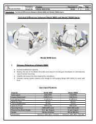
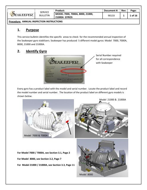
SERVICEBULLETINProcedure: <strong>ANNU</strong>AL INSPECTION INSTRUCTIONS1. PurposeProduct: Document #: Rev: Page:MODEL 7000, 7000A, 8000, 21000,21000A <strong>GYRO</strong>S<strong>90133</strong> 1 1 of 16This service bulletin identifies the specific areas to check for the recommended annual inspection ofthe <strong>Seakeeper</strong> gyro stabilizers. <strong>Seakeeper</strong> has produced 5 different model gyros: Model 7000, 7000A,8000, 21000 and 21000A.2. Identify GyroSerial Number requiredfor all correspondencewith <strong>Seakeeper</strong>Every gyro has a product label with the model and serial number. Locate the product label and recordthe model number and serial number. The location of the product label on different gyro models isshown below.Model 21000 & 21000AModel 7000 & 7000AFor Model 7000 / 7000A, see Section 3.1, Page 2For Model 8000, see Section 3.2, Page 7For Model 21000 / 21000A, see Section 3.3, Page 11Model 8000
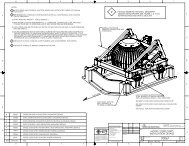
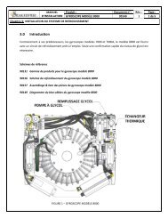
SERVICEBULLETINProcedure: <strong>ANNU</strong>AL INSPECTION INSTRUCTIONS Document #: Rev: Page:<strong>90133</strong> 1 2 of 163. Annual Inspection Instructions3.1 Model 7000 / 7000A :3.1.1 Cooling System -Confirm gyro’s 24 VDC breaker in ON and listen / feel coolant circulation pump to confirm it isrunning and operating properly. Pump is located on the port side of the aft transverse brace of thegyro frame as shown in below photo. If you hear intermittent noises (pump cavitation) , this mayindicate air in the coolant plumbing and the system should be filled / purged per instructionsprovided in installation manual ( manual is available for download athttp://www.seakeeper.com/downloads_manuals.php)COOLANT CIRCULATIONPUMPHEAT EXCHANGERModel 7000 / 7000 A COOLING COMPONENTSInspect heat exchanger and fittings for any leaks or severe corrosion. The heat exchanger islocated below the aft transverse brace of the gyro frame as shown in above photo. Insure seawatercooling hoses are isolated from incoming seawater (i.e: close sea-cock) and disconnect seawaterinlet and outlet hoses and flush heat exchanger with fresh water to insure there are no internalblockages. Once flushing is complete , make certain to secure seawater inlet / outlet hoses to theheat exchanger with appropriate hose clamps and open the appropriate sea-cock for the waterintake.
SERVICEBULLETINProcedure: <strong>ANNU</strong>AL INSPECTION INSTRUCTIONS Document #: Rev: Page:<strong>90133</strong> 1 3 of 16M7000 gyros with serial numbers G067 and above are supplied with zinc anodes installed at thebottom of the heat exchanger near the end where the sea water inlets and outlets are located. Forgyros with serial numbers of G067 and above, remove the plug / zinc at the bottom of the heatexchanger and inspect the zinc anode. If erosion is estimated to be more that 50%, replace anode.If zinc anode is gone, make point to inspect every 2 months until erosion rate is determined. Theanode is a 3/8 inch diameter x ¾ inch long pencil in a ¼” NPT plug. Contact <strong>Seakeeper</strong> Service Dept.to obtain the replacement anodes. Apply Teflon paste pipe thread sealant or Teflon pipe threadtape to the plug threads when re-installing.LOCATION OF ZINCANODEModel 7000 / 7000A ZINC ANODE LOCATIONInspect gyro sea water cooling pump for proper operation. Observe overboard discharge fornormal flow. Minimum flow should be 2 GPM ( 7.6 lpm) .Obvious low flows may indicate flowrestrictions.Inspect all cooling hoses and fittings for damage / chafing including those cooling the remotelymounted motor drive box– in the event a hose needs to be replaced, contact <strong>Seakeeper</strong> ServiceDept. for hose specifications and guidelines for replacing any cooling hose.Insure that the coolant thermostatic valve knob is turned all the way in the clockwise direction asshown below. Inspect bilge area under gyro for any indication of coolant leaks .
SERVICEBULLETINProcedure: <strong>ANNU</strong>AL INSPECTION INSTRUCTIONS Document #: Rev: Page:<strong>90133</strong> 1 4 of 163.1.2 Brake System –Inspect area under brake cylinders for any indication of oil leaks from the cylinder rod seal shownbelow. Some oil residue under the rod seals on the bottom of the cylinders is normal but any dripsshowing below the cylinders in the bilge should be investigated further. If a cylinder seal is showingsigns of a significant leak, replace suspect cylinder – contact <strong>Seakeeper</strong> service for partidentification and replacement procedure. Leaks will eventually result in a “Low Brake Pressure”alarm condition which will not allow operation of the gyro. Note that a brake service kit is requiredfor any brake system component replacement – contact your local representative or <strong>Seakeeper</strong>Service Department for details.BRAKE CYLINDERBUSHING<strong>SB</strong>RAKE CYLINDER RODSEALSObserve gyro during operation in Sea mode while in some swells / waves to cause the gyro toprecess back and forth. Visible play or wear between the brake cylinders and their mountand/or the brake cylinder rod-end and the crank arm on the gyro as shown above meritsreplacing the composite brake linkage bushings. The expected life of the brake linkage bushingsis 2000 hrs of SEA time . The bushings may need replacing sooner if operated in heavy seaconditions more often where the loading is higher. Contact <strong>Seakeeper</strong> service for parts andreplacement procedures.
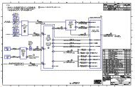
SERVICEBULLETINProcedure: <strong>ANNU</strong>AL INSPECTION INSTRUCTIONS Document #: Rev: Page:<strong>90133</strong> 1 5 of 16Inspect brake hoses for any significant chafing through the outer jacket of the hose.Inspect all hose and manifold fittings for any significant corrosion or leaks and contact<strong>Seakeeper</strong> service for replacement parts if required.For those models with exposed pin retaining clips for brake rod-end as shown below, inspectcondition of retaining ring and washers. Clean away any excess corrosion and pack area withsmall amount of waterproof grease to aid in preventing corrosion.RETAININGRINGWASHER3.1.3 Electrical Cables / Connections –Inspect all cables located on the gyro frame and sphere for damage or chafing. Note thatmanually moving the sphere may make inspection easier. See operators manual for procedureto unlock the brake and manually rotate the spherical enclosure while the flywheel is notspinning.Inspect all electrical connectors on the gyro control box and motor drive box for damage orcorrosion. Removing the connector is not necessary – just confirm no external connectordamage or corrosion. If corrosion is present , follow <strong>Seakeeper</strong> Service Bulletin #90084 forcleaning and protecting connectors.
SERVICEBULLETINProcedure: <strong>ANNU</strong>AL INSPECTION INSTRUCTIONS Document #: Rev: Page:<strong>90133</strong> 1 6 of 16Inspect ground and / or bond cable connections for corrosion and clean , re-install if required.Ground cable connection locations are shown below.GroundConnectionsCheck gimbal angle sensor calibration. See <strong>Seakeeper</strong> Service Bulletin 90083 for procedures toperform this task.3.1.4 Gyro Enclosure / Foundation –Inspect enclosure, foundation frame, and hardware for corrosion and areas where paint shouldbe reapplied. Any loose paint should be removed and cleaned back to bare metal andappropriate primer and top-coat paint system applied to seal the bare metal. See ServiceBulletin 90026 for paint information.
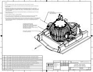
SERVICEBULLETINProcedure: <strong>ANNU</strong>AL INSPECTION INSTRUCTIONS Document #: Rev: Page:<strong>90133</strong> 1 7 of 163.2 Model 8000 :3.2.1 Cooling System -Remove coolant fill cap and confirm coolant level is approximately as shown in the below photo.Correct Coolant LevelModel 8000 Coolant LevelThe Model 8000 glycol coolant pump typically runs only during RUN mode. For maintenance, theglycol pump can be turned ON from the display. Press “MENU” repeatedly until the SERVICE pageis displayed. Press “DOWN” repeatedly until the “GLY PUMP” is selected and press “MENU”. Atthe GLYCOL PUMP page press UP and DOWN to turn the pump ON and OFF. Note that there areminimum on and off times for the pump, so the pump may not immediately respond to acommand.Check flow by removing coolant fill cap and looking in the top of the heat exchanger surge tank.
SERVICEBULLETINProcedure: <strong>ANNU</strong>AL INSPECTION INSTRUCTIONS Document #: Rev: Page:<strong>90133</strong> 1 8 of 16Inspect heat exchanger and fittings for any leaks or severe corrosion. The heat exchanger islocated alongside the brake cylinders on the units foundation as shown in below image. Insureseawater cooling hoses are isolated from incoming seawater (i.e: close sea-cock) and disconnectseawater inlet and outlet hoses. Remove plug containing zinc anode on the heat exchanger andinspect. If erosion is estimated to be more that 50%, replace anode. If zinc anode is gone, makepoint to inspect every 2 months until erosion rate is determined. The anode is a 3/8 inch diameter x¾ inch long pencil in a ¼” NPT plug. Contact <strong>Seakeeper</strong> Service Dept. to obtain the replacementanodes. Apply Teflon paste pipe thread sealant or Teflon pipe thread tape to the plug threads whenre-installing.Flush heat exchanger with fresh water to insure there are no internal blockages. Once flushing iscomplete , make certain to secure seawater inlet / outlet hoses to the heat exchanger withappropriate hose clamps and open the appropriate sea-cock for the water intake.COMPACTMOTOR DRIVEBOX<strong>GYRO</strong> CONTROLBOXHEATEXCHANGERZINC ANODE/ PLUGCOOLANTPUMPInspect gyro sea water cooling pump for proper operation. Observe overboard discharge fornormal flow. Minimum required flow is 4 GPM ( 15.1 LPM) Obvious low flows may indicate flowrestrictions.Inspect all hoses and fittings for damage / chafing – in the event a hose needs to be replaced,contact <strong>Seakeeper</strong> Service Dept. for hose specifications and guidelines for replacing any coolinghose. Inspect bilge area under gyro for any indication of coolant leaks .
SERVICEBULLETINProcedure: <strong>ANNU</strong>AL INSPECTION INSTRUCTIONS Document #: Rev: Page:<strong>90133</strong> 1 10 of 163.2.3 Electrical Cables / Connections –Inspect all cables located on the gyro frame and sphere for damage or chafing. Note thatmanually moving the sphere may make inspection easier. See operators manual for procedureto unlock the brake while the flywheel is not spinning.Inspect all electrical connectors on the gyro control box and motor drive box for damage orcorrosion. Removing the connector is not necessary – just confirm no external connectordamage or corrosion. If corrosion is present , follow <strong>Seakeeper</strong> Service Bulletin #90084 forcleaning and protecting connectors.Inspect ground and/or bond cable connections for corrosion and clean , re-install if required.Ground cable connection locations are shown below.GROUND / BONDCONNECTIONSCheck gimbal angle sensor calibration. See <strong>Seakeeper</strong> Service Bulletin 90083 for procedures toperform this task.3.2.4 Gyro Enclosure / Foundation –Inspect enclosure, foundation frame, and hardware for corrosion and areas where paint shouldbe reapplied. Any loose paint should be removed and cleaned back to bare metal andappropriate primer and top-coat paint system applied to seal the bare metal. See ServiceBulletin 90026 for paint information.
SERVICEBULLETINProcedure: <strong>ANNU</strong>AL INSPECTION INSTRUCTIONS Document #: Rev: Page:<strong>90133</strong> 1 11 of 163.3 Model 21000 / 21000A :3.3.1 Cooling System -Remove coolant fill cap and confirm coolant level is approximately as shown in the below photo.COOLANT FILL LEVELSURGE TANKHEAT EXCHANGERZINC ANODEModel 21000 /21000A Coolant LevelFOR MODEL 21000, confirm gyro’s 24 VDC breaker in ON and listen / feel glycol coolant pump toconfirm it is running and operating properly. Pump is located on the units frame under the brakemanifold as shown in below photo. Flow can be observed by removing coolant fill cap and lookingin the top of the heat exchanger surge tank.BRAKEMANIFOLDCOOLANT PUMP
SERVICEBULLETINProcedure: <strong>ANNU</strong>AL INSPECTION INSTRUCTIONS Document #: Rev: Page:<strong>90133</strong> 1 12 of 16FOR MODEL 21000A, the glycol coolant pump typically runs only during RUN mode. Formaintenance, the glycol pump can be turned ON from the display. Press “MENU” repeatedlyuntil the SERVICE page is displayed. Press “DOWN” repeatedly until the “GLY PUMP” is selectedand press “MENU”. At the GLYCOL PUMP page press UP and DOWN to turn the pump ON andOFF. Note that there are minimum on and off times for the pump, so the pump may notimmediately respond to a command.Pump is located below the brake cylinders as shown in above image. Check flow by removingcoolant fill cap and looking in the top of the heat exchanger surge tank.Inspect heat exchanger and fittings for any leaks or severe corrosion. Insure seawater coolinghoses are isolated from incoming seawater (i.e: close sea-cock) and disconnect seawater inlet andoutlet hoses. Remove plug containing zinc anode on the heat exchanger and inspect. If erosion isestimated to be more that 50%, replace anode. If zinc anode is gone, make point to inspect every 2months until erosion rate is determined. The anode is a 3/8 inch diameter x ¾ inch long pencil in a¼” NPT plug. Contact <strong>Seakeeper</strong> Service Dept. to obtain the replacement anodes. Apply Teflonpaste pipe thread sealant or Teflon pipe thread tape to the plug threads when re-installing.Flush heat exchanger with fresh water to insure there are no internal blockages. Once flushing iscomplete , make certain to secure seawater inlet / outlet hoses to the heat exchanger withappropriate hose clamps and open the appropriate sea-cock for the water intake.Inspect gyro sea water cooling pump for proper operation. Observe overboard discharge fornormal flow. Minimum flow is 4 GPM ( 15.1 lpm)Obvious low flows may indicate flow restrictions.Inspect all hoses and fittings for damage / chafing – in the event a hose needs to be replaced,contact <strong>Seakeeper</strong> Service Dept. for hose specifications and guidelines for replacing any coolinghose. Inspect bilge area under gyro for any indication of coolant leaks .
SERVICEBULLETINProcedure: <strong>ANNU</strong>AL INSPECTION INSTRUCTIONS Document #: Rev: Page:<strong>90133</strong> 1 13 of 163.3.2 Brake System –Inspect area under brake cylinders for any indication of oil leaks from the cylinder rod sealshown below. Some oil residue under the rod seals on the bottom of the cylinders is normal butany drips showing below the cylinders in the bilge should be investigated further. If a cylinderseal is showing signs of a significant leak, replace suspected leaking cylinder. Leaks willeventually result in a “Low Brake Pressure” alarm condition which will not allow operation of thegyro. Note that a brake service kit is required for any brake system component replacement –contact your local representative or <strong>Seakeeper</strong> Service Department for details.BRAKE CYLINDERBUSHINGS(ON EACH OF 4 CYLINDERS)BRAKE CYLINDER ROD SEALS(ON EACH OF 4 CYLINDERS)Observe gyro during operation in Sea mode while in some swells / waves to cause the gyro toprecess back and forth . Visible play or wear between the brake cylinders and their mountand/or the brake cylinder rod-end and the crank arm on the gyro shown above merits replacingthe composite brake linkage bushings. The expected life of the brake linkage bushings is 2000hrs of SEA time . The bushings may need replacing sooner if operated in heavy sea conditionsmore often where the loading is more severe. Contact <strong>Seakeeper</strong> service for parts andreplacement procedures.Inspect brake hoses for any significant chafing through the outer jacket of the hose.Inspect all hose and brake manifold fittings for any significant corrosion or leaks and contact<strong>Seakeeper</strong> service for replacement parts if required.
SERVICEBULLETINProcedure: <strong>ANNU</strong>AL INSPECTION INSTRUCTIONS Document #: Rev: Page:<strong>90133</strong> 1 14 of 163.2.3 Electrical Cables / Connections –Inspect all cables located on the gyro frame and sphere for damage or chafing. Note thatmanually moving the sphere may make inspection easier. See operators manual for procedureto unlock the brake while the flywheel is not spinning.Inspect all electrical connectors on the gyro control box and motor drive box for damage orcorrosion. Removing the connector is not necessary – just confirm no external connectordamage or corrosion. If corrosion is present , follow <strong>Seakeeper</strong> Service Bulletin 90084 forcleaning and protecting connectors.Inspect ground and/or bond cable connections for corrosion and clean , re-install if required.Ground cable connection locations are shown below.GROUND / BONDCABLE CONNECTIONLOCATIONSCheck gimbal angle sensor calibration. See <strong>Seakeeper</strong> Service Bulletin 90083 for procedures toperform this task.
SERVICEBULLETINProcedure: <strong>ANNU</strong>AL INSPECTION INSTRUCTIONS Document #: Rev: Page:<strong>90133</strong> 1 15 of 163.2.4 Gyro Enclosure / Foundation –Inspect enclosure, foundation frame, and hardware for corrosion and areas where paint shouldbe reapplied. Any loose paint should be removed and cleaned back to bare metal andappropriate primer and top-coat paint system applied to seal the bare metal. See ServiceBulletin 90026 for paint information.Inspect all eight retainer screws ( 2 per isolation mount )shown below and confirm all are tightand safety retaining wire is in place.RETAINING SCREWS2 PER ISOLATION MOUNTISOLATION MOUNT
SERVICEBULLETINProcedure: <strong>ANNU</strong>AL INSPECTION INSTRUCTIONS Document #: Rev: Page:<strong>90133</strong> 1 16 of 16REVISION HISTORYREVISION DESCRIPTION OF CHANGES DATE APPROVED1 INITIAL RELEASE 18MAY11 BHSSEAKEEPER, INC.P.O. BOX 809, 44731 ST. ANDREWS CHURCH ROAD, CALIFORNIA, MARYLAND, 20619, U.S.APHONE: 410-326-1590 FAX: 410-326-1199 E-MAIL: customerservice@seakeeper.com