Elektros montavimo ir eksploatavimo instrukcija - komfovent
Elektros montavimo ir eksploatavimo instrukcija - komfovent
Elektros montavimo ir eksploatavimo instrukcija - komfovent
- No tags were found...

You also want an ePaper? Increase the reach of your titles
YUMPU automatically turns print PDFs into web optimized ePapers that Google loves.
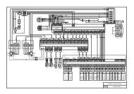
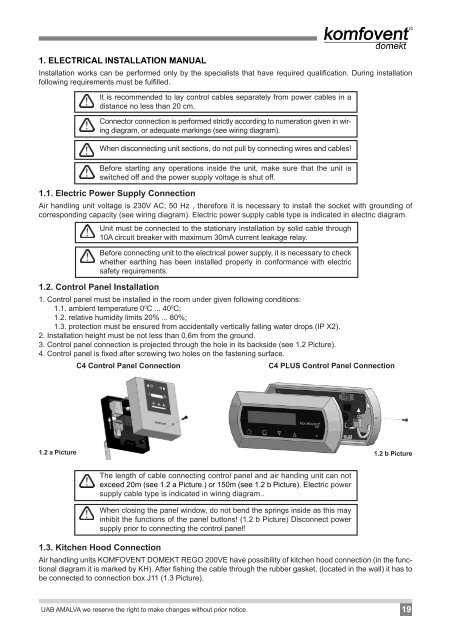
1. ELECTRICAL INSTALLATION MANUALInstallation works can be performed only by the specialists that have requ<strong>ir</strong>ed qualification. During installationfollowing requ<strong>ir</strong>ements must be fulfilled.It is recommended to lay control cables separately from power cables in adistance no less than 20 cm.Connector connection is performed strictly according to numeration given in w<strong>ir</strong>ingdiagram, or adequate markings (see w<strong>ir</strong>ing diagram).When disconnecting unit sections, do not pull by connecting w<strong>ir</strong>es and cables!Before starting any operations inside the unit, make sure that the unit isswitched off and the power supply voltage is shut off.1.1. Electric Power Supply ConnectionA<strong>ir</strong> handling unit voltage is 230V AC; 50 Hz , therefore it is necessary to install the socket with grounding ofcorresponding capacity (see w<strong>ir</strong>ing diagram). Electric power supply cable type is indicated in electric diagram.Unit must be connected to the stationary installation by solid cable through10A c<strong>ir</strong>cuit breaker with maximum 30mA current leakage relay.Before connecting unit to the electrical power supply, it is necessary to checkwhether earthing has been installed properly in conformance with electricsafety requ<strong>ir</strong>ements.1.2. Control Panel Installation1. Control panel must be installed in the room under given following conditions:1.1. ambient temperature 0 0 C ... 40 0 C;1.2. relative humidity limits 20% ... 80%;1.3. protection must be ensured from accidentally vertically falling water drops (IP X2).2. Installation height must be not less than 0,6m from the ground.3. Control panel connection is projected through the hole in its backside (see 1.2 Picture).4. Control panel is fixed after screwing two holes on the fastening surface.C4 Control Panel ConnectionC4 PLUS Control Panel Connection1.2 a Picture 1.2 b PictureThe length of cable connecting control panel and a<strong>ir</strong> handing unit can notexceed 20m (see 1.2 a Picture.) or 150m (see 1.2 b Picture). Electric powersupply cable type is indicated in w<strong>ir</strong>ing diagram..When closing the panel window, do not bend the springs inside as this mayinhibit the functions of the panel buttons! (1.2 b Picture) Disconnect powersupply prior to connecting the control panel!1.3. Kitchen Hood ConnectionA<strong>ir</strong> handling units KOMFOVENT DOMEKT REGO 200VE have possibility of kitchen hood connection (in the functionaldiagram it is marked by KH). After fishing the cable through the rubber gasket, (located in the wall) it has tobe connected to connection box J11 (1.3 Picture).UAB AMALVA we reserve the right to make changes without prior notice.19