Elektros montavimo ir eksploatavimo instrukcija - komfovent
Elektros montavimo ir eksploatavimo instrukcija - komfovent
Elektros montavimo ir eksploatavimo instrukcija - komfovent
- No tags were found...

Create successful ePaper yourself
Turn your PDF publications into a flip-book with our unique Google optimized e-Paper software.
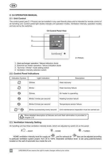
EN2. C4 OPERATION MANUAL2.1. Unit ControlThe control panel (see 2.1 Picture) can be installed in any user-friendly place and is intended for remote control ofa<strong>ir</strong> handling unit. Control panel light diodes indicate unit operation modes. Ventilation intensity, operation modesand are set by the switches.C4 Control Panel View1 2342.1 Picture1. Heat exchanger operation / failure indication diode2. Electrical a<strong>ir</strong> heater operation / failure indication diode3. “Summer / Winter“ mode setting switch4. Ventilation intensity selection switch2.2. Control Panel IndicationsIndication Symbol Light Indication DescriptionShinesBlinksShinesBlinks 3 times per secondBlinks 8 times per secondHeat recoveryHeat recovery failureA<strong>ir</strong> heater is operatingHeating function failureTemperature sensor failure+ Blinks successively every second Unit maintenance inspection must be carried outMore detailed description of failures and and the<strong>ir</strong> elimination is provided inchapter 2.9.2.3. Ventilation Intensity SettingA<strong>ir</strong> handling unit has three ventilation intensity levels, which are adjusted by switch (4) on the panel:– AWAY – HOME – TURBOHOME ventilation intensity level for supply a<strong>ir</strong> , and for exhaust a<strong>ir</strong> fans can be adjusted accordingto particular ventilation system project, from 20 to 100%. Des<strong>ir</strong>able ventilation level is set using potentiometerslocated on the wall of automatic box inside the unit.22 UAB AMALVA we reserve the right to make changes without prior notice.