MODEL FD-RD AND FDD-RD FIRE DAMPER - NCA Manufacturing
MODEL FD-RD AND FDD-RD FIRE DAMPER - NCA Manufacturing
MODEL FD-RD AND FDD-RD FIRE DAMPER - NCA Manufacturing
- No tags were found...

Create successful ePaper yourself
Turn your PDF publications into a flip-book with our unique Google optimized e-Paper software.
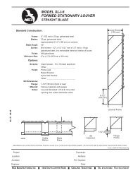
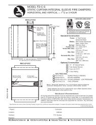
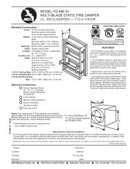
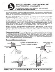
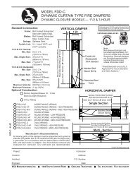
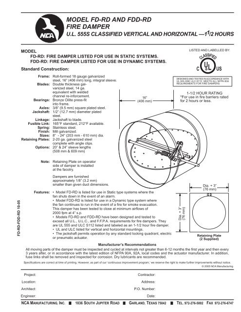
<strong>MODEL</strong> <strong>FD</strong>-<strong>RD</strong> <strong>AND</strong> <strong>FD</strong>D-<strong>RD</strong><strong>FIRE</strong> <strong>DAMPER</strong>U.L. 555S CLASSIFIED VERTICAL <strong>AND</strong> HORIZONTAL —1 1 /2 HOURS<strong>MODEL</strong><strong>FD</strong>-<strong>RD</strong>: <strong>FIRE</strong> <strong>DAMPER</strong> LISTED FOR USE IN STATIC SYSTEMS.<strong>FD</strong>D-<strong>RD</strong>: <strong>FIRE</strong> <strong>DAMPER</strong> LISTED FOR USE IN DYNAMIC SYSTEMS.Standard Construction:Frame: Roll-formed 18 gauge galvanizedsteel, 16” (406 mm) long, integral sleeve.Blades: Double thickness galvanizedsteel, 14 ga.equivalent with weldedchannel re-inforcement.Bearings: Bronze Oilite press-fitinto frame.Axles: 3/8” (9.5 mm) square plated steel.Jackshaft: 1/2” (12.7 mm) diameter platedsteel.Linkage: Jackshaft to blade.Fusible Link: 165°F standard, 212°F available.Spring: Stainless steel.Finish: Mill galvanized.Sizes: 8” - 24” (203 mm - 610 mm) dia.Retaining Plates: 2-20 ga. galvanized steelcomplete with angle clips.Options: 20” & 24” sleeve lengths(508 mm & 609 mm)16”(406 mm)LISTED <strong>AND</strong> LABELLED BY:CCLASSIFIEDU L RUSDESIGNED <strong>AND</strong> TESTED IN ACCO<strong>RD</strong>ANCE WITHUL-555 <strong>AND</strong> ULC-S112. MEETS ALL NFPA-90AREQUIREMENTS FOR <strong>FIRE</strong> <strong>DAMPER</strong>S.1-1/2 HOUR RATING*For use in fire barriers ratedfor 2 hours or less.Note:Retaining Plate on operatorside of damper is installedat the facotry.<strong>FD</strong>-<strong>RD</strong>-<strong>FD</strong>D-<strong>RD</strong> 10-05Features:Dampers are furnishedapproximately 1/8” (3.2 mm)smaller than given duct dimensions.• Model <strong>FD</strong>-<strong>RD</strong> is listed for use in Static type systems where thefan shuts down in the event of an alarm.• Model <strong>FD</strong>D-<strong>RD</strong> is listed for use in a Dynamic type system wherethe fan continues to run in the event of a fire for smoke evacuation.This damper has been tested to close at minimum airflows of2000 fpm at 4” s.p.• Models <strong>FD</strong>-<strong>RD</strong> and <strong>FD</strong>D-<strong>RD</strong> have been designed and tested toexceed all U.L., U.L.C., and F.F.P.A. requirements for fire dampers. Theyare UL 555 and ULC S112 listed and labeled as an 1-1/2 hour fire damper.• UL and ULC listed for vertical and horizontal mountings.• The jackshaft permits operation by any standard locking quadrant, electricor pneumatic actuator.Retaining Plate(2 Supplied)Specifications are correct at time of printing. However, as part of our ‘continuous improvement program,’ we reserve the right to make further improvements without notice.© 2005 <strong>NCA</strong> <strong>Manufacturing</strong>Dia. + 3”(76 mm)Dia. + 3”(76 mm)Manufacturer’s RecommendationsAll moving parts of the damper must be inspected and cycled at intervals not greater than 6-12 months the first year and then every3 years after, or in accordance with the latest edition of NFPA 90A, 92A, local codes and the actuator manufacturer. In addition,fuse links shall be removed and inspected for corrosion. Dry lubricants are recommended.Project:Location:Architect:Engineer:Contractor:Address:P.O. Number:Date:<strong>NCA</strong> MANUFACTURING, INC. 1036 SOUTH JUPITER ROAD GARL<strong>AND</strong>, TEXAS 75042 TEL. 972-276-5002 FAX 972-276-6747
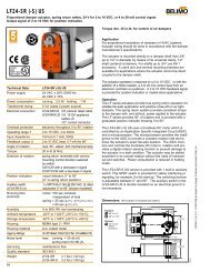
<strong>MODEL</strong> <strong>FD</strong>-<strong>RD</strong> <strong>AND</strong> <strong>FD</strong>D-<strong>RD</strong><strong>FIRE</strong> <strong>DAMPER</strong>U.L. 555S CLASSIFIED VERTICAL <strong>AND</strong> HORIZONTAL —1 1 /2 HOURS© 2005 <strong>NCA</strong> <strong>Manufacturing</strong>Pressure drop testing was done by an independent laboratory to the AMCA Standard 500-D, Fig. 5.3ductwork upstream & downstream.PRESSURE DROPPRESSURE DROP (INCHES W.G.)8” DIAMETER24” DIAMETERFACE VELOCITY (FPM)<strong>FD</strong>-<strong>RD</strong>-<strong>FD</strong>D-<strong>RD</strong>-02-06LEAKAGE OBTAINED IN TEST OF 8” DIAMETER <strong>AND</strong> 24” DIAMETERWAS LESS THAN 1 CFM/SQ. FT.<strong>NCA</strong> MANUFACTURING, INC. 1036 SOUTH JUPITER ROAD GARL<strong>AND</strong>, TEXAS 75042 TEL. 972-276-5002 FAX 972-276-6747