MARITIME TACTICAL WIDE AREA NETWORKING (MTWAN ...
MARITIME TACTICAL WIDE AREA NETWORKING (MTWAN ...
MARITIME TACTICAL WIDE AREA NETWORKING (MTWAN ...
- No tags were found...

Create successful ePaper yourself
Turn your PDF publications into a flip-book with our unique Google optimized e-Paper software.
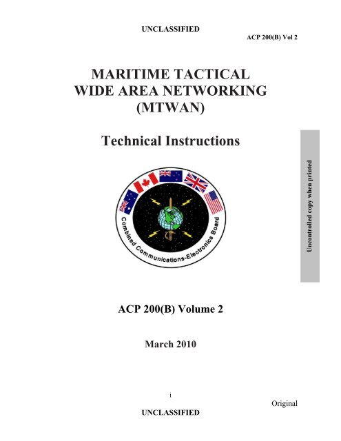
Uncontrolled copy when printedUNCLASSIFIEDACP 200(B) Vol 2<strong>MARITIME</strong> <strong>TACTICAL</strong><strong>WIDE</strong> <strong>AREA</strong> <strong>NETWORKING</strong>(<strong>MTWAN</strong>)Technical InstructionsACP 200(B) Volume 2March 2010iUNCLASSIFIEDOriginal
Uncontrolled copy when printedUNCLASSIFIEDFOREWORDACP 200(B) Vol 21. The Combined Communications-Electronics Board (CCEB) is comprised of thefive member nations, Australia, Canada, New Zealand, United Kingdom andUnited States and is the Sponsoring Authority for all Allied CommunicationsPublications (ACPs). ACPs are raised and issued under common agreementbetween the member nations.2. ACP 200(B) Volume 2, <strong>MARITIME</strong> <strong>WIDE</strong> <strong>AREA</strong> <strong>TACTICAL</strong> <strong>NETWORKING</strong>(<strong>MTWAN</strong>) Technical Instructions, is an UNCLASSIFIED CCEB publication.3. This publication contains Allied military information for official purposes only.4. This ACP is to be maintained and amended in accordance with the provisions ofthe current version of ACP 198.iiUNCLASSIFIEDOriginal
Uncontrolled copy when printedUNCLASSIFIEDACP 200(B) Vol 2THE COMBINED COMMUNICATIONS-ELECTRONICS BOARDLETTER OF PROMULGATIONFOR ACP 200(B) Volume 21. The purpose of this Combined Communications-Electronics Board (CCEB) Letterof Promulgation is to implement ACP 200(B) Vol 2 within the Armed Forces of theCCEB Nations. ACP 200(B) Vol 2, <strong>MARITIME</strong> <strong>WIDE</strong> <strong>AREA</strong> <strong>NETWORKING</strong>(<strong>MTWAN</strong>) Technical Instructions, is an UNCLASSIFIED publication developed forAllied use under the direction of the CCEB Principals2. ACP 200(B) Volume 2 is effective upon receipt for CCEB Nations and whendirected by the NATO Military Committee (NAMILCOM) for NATO nations. ACP200(B) Volume 1 and 2 will supersede ACP 200(B), which shall be destroyed inaccordance with national regulations.EFFECTIVE STATUSPublication Effective for Date AuthorityACP 200(B) Vol 2 CCEB On Receipt LOP3. All proposed amendments to the publication are to be forwarded to the nationalcoordinating authorities of the CCEB or NAMILCOM.For the CCEB PrincipalsPaul FosterP. FOSTERMajor, CFCCEB Permanent SecretaryiiiUNCLASSIFIEDOriginal
Uncontrolled copy when printedUNCLASSIFIEDACP 200(B) Vol 2RECORD OF MESSAGE CORRECTIONSIdentification of Message CorrectionAnd Date Time GroupDTGCorrectionDate EnteredEntered by(Signature, Name,rank)ivUNCLASSIFIEDOriginal
Uncontrolled copy when printedUNCLASSIFIEDTABLE OF CONTENTSACP 200(B) Vol 2FOREWORD ......................................................................................................................................................... iiLETTER OF PROMULGATION ......................................................................................................................... iiiRECORD OF MESSAGE CORRECTIONS ........................................................................................................ ivTABLE OF CONTENTS ....................................................................................................................................... vLIST OF FIGURES ................................................................................................................................................ vLIST OF TABLES ................................................................................................................................................ viCHAPTER 1........................................................................................................................................................ 1-1NETWORK ARCHITECTURE.......................................................................................................................... 1-1INTRODUCTION ............................................................................................................................................... 1-1AIM ..................................................................................................................................................................... 1-1OVERVIEW ....................................................................................................................................................... 1-1DESCRIPTION ................................................................................................................................................... 1-1ROUTING ARCHITECTURE (RA) .................................................................................................................. 1-2AUTONOMOUS SYSTEMS (AS) ..................................................................................................................... 1-2TOPOLOGY ....................................................................................................................................................... 1-3SINGLE AS TGAN TOPOLOGY ...................................................................................................................... 1-3MULTIPLE AS TGAN TOPOLOGY ................................................................................................................ 1-3ROUTING PROTOCOLS ................................................................................................................................... 1-5COMMUNICATIONS ARCHITECTURE (CA) ............................................................................................... 1-5POINT-TO-POINT ............................................................................................................................................. 1-5MULTI-MEMBER ............................................................................................................................................. 1-7SECURITY ARCHITECTURE (SA) ................................................................................................................. 1-8NODE DESCRIPTIONS ..................................................................................................................................... 1-8GENERIC MOBILE NODE ............................................................................................................................... 1-8CONCLUSION ................................................................................................................................................... 1-8CHAPTER 2........................................................................................................................................................ 2-1QUALITY OF SERVICE ................................................................................................................................... 2-1INTRODUCTION ............................................................................................................................................... 2-1AIM ..................................................................................................................................................................... 2-1OVERVIEW ....................................................................................................................................................... 2-1DEFINITION ...................................................................................................................................................... 2-1LINK THROUGHPUT / BOTTLENECK .......................................................................................................... 2-2MAXIMIZING LINK THROUGHPUT ............................................................................................................. 2-2LATENCY .......................................................................................................................................................... 2-2TCP CONGESTION CONTROL ....................................................................................................................... 2-3CONTROLLING LESS URGENT TRAFFIC .................................................................................................... 2-3OBJECTIVE ....................................................................................................................................................... 2-3VISIBILITY ........................................................................................................................................................ 2-4TYPES OF APPLICATIONS ............................................................................................................................. 2-4PERFORMANCE MEASURES ......................................................................................................................... 2-4TRAFFIC CLASSIFICATION ........................................................................................................................... 2-5CONTROL .......................................................................................................................................................... 2-5SERVICE LEVELS ............................................................................................................................................ 2-5PRIORITY MARKING OF <strong>MTWAN</strong> TRAFFIC .............................................................................................. 2-7SERVICE CLASSES .......................................................................................................................................... 2-7ASSURED FORWARDING SERVICES CLASSES ......................................................................................... 2-9COMPRESSION ............................................................................................................................................... 2-10TYPES OF COMPRESSION ............................................................................................................................ 2-10PAIR WISE CONFIGURATION ..................................................................................................................... 2-10QOS SOLUTIONS ............................................................................................................................................ 2-11INTEROPERABILITY ..................................................................................................................................... 2-11vUNCLASSIFIEDOriginal
Uncontrolled copy when printedUNCLASSIFIEDviUNCLASSIFIEDACP 200(B) Vol 2PASS THROUGH FAILOVER ........................................................................................................................ 2-11NETWORK TOPOLOGY ................................................................................................................................ 2-11FUTURE WORK .............................................................................................................................................. 2-11MAPPING IER TO QOS .................................................................................................................................. 2-12IPV6 .................................................................................................................................................................. 2-12CONCLUSION ................................................................................................................................................. 2-12CHAPTER 3........................................................................................................................................................ 3-1NETWORK MANAGEMENT ........................................................................................................................... 3-1INTRODUCTION ............................................................................................................................................... 3-1AIM ..................................................................................................................................................................... 3-1OVERVIEW ....................................................................................................................................................... 3-1NETWORK MANAGEMENT ARCHITECTURE (HIERARCHY) ................................................................. 3-1PRIMARY NOC ................................................................................................................................................. 3-1NATIONAL NOC ............................................................................................................................................... 3-1NODE LEVEL .................................................................................................................................................... 3-1NETWORK MANAGEMENT ELEMENTS ..................................................................................................... 3-2PERFORMANCE MANAGEMENT .................................................................................................................. 3-2SECURITY MANAGEMENT............................................................................................................................ 3-2REMOTE OR LOCAL MANAGEMENT .......................................................................................................... 3-3GENERATION OF REPORTS........................................................................................................................... 3-4SECURITY RESPONSIBILITY ........................................................................................................................ 3-4TOOLS ................................................................................................................................................................ 3-4ANNEX A TO CHAPTER 3 ........................................................................................................................... 3A-1ANNEX B TO CHAPTER 3 ............................................................................................................................ 3B-1APPENDIX 1 TO ANNEX B TO CHAPTER 3 ............................................................................................ 3A1-1CHAPTER 4........................................................................................................................................................ 4-1TRANSPORT SERVICES .................................................................................................................................. 4-1INTRODUCTION ............................................................................................................................................... 4-1AIM ..................................................................................................................................................................... 4-1OVERVIEW ....................................................................................................................................................... 4-1TCP OVER HIGH LATENCY LINKS .............................................................................................................. 4-2IP FRAGMENTATION ...................................................................................................................................... 4-3PERFORMANCE ENHANCING TECHNIQUES ............................................................................................. 4-3CHAPTER 5........................................................................................................................................................ 5-1NETWORK NAMING AND ADDRESSING .................................................................................................... 5-1INTRODUCTION ............................................................................................................................................... 5-1AIM ..................................................................................................................................................................... 5-1OVERVIEW ....................................................................................................................................................... 5-1HOST NAMING CONVENTION ...................................................................................................................... 5-1DOMAIN NAMING CONVENTION ................................................................................................................ 5-5IP SUBNETTING AND MULTICAST ADDRESSING .................................................................................... 5-7CLASS D MULTICAST ADDRESSING........................................................................................................... 5-7UNICAST CLASS C IP SUBNETTING ............................................................................................................ 5-8MULITCAST SUBNETTING ............................................................................................................................ 5-8IP ADDRESSING CONVENTION .................................................................................................................... 5-8IP ADDRESS AUTHORITY TASKS ................................................................................................................ 5-9UNIT ASSIGNMENT OF HOSTS ..................................................................................................................... 5-9CHAPTER 6........................................................................................................................................................ 6-1ROUTING ........................................................................................................................................................... 6-1INTRODUCTION ............................................................................................................................................... 6-1AIM ..................................................................................................................................................................... 6-1OVERVIEW ....................................................................................................................................................... 6-1ROUTING ARCHITECTURES ......................................................................................................................... 6-2Original
Uncontrolled copy when printedUNCLASSIFIEDACP 200(B) Vol 2INTERIOR TGAN ROUTING ........................................................................................................................... 6-6EXTERIOR TGAN ROUTING .......................................................................................................................... 6-7REDUCING ROUTING PROTOCOL TRAFFIC TO THE ALLIED WAN ..................................................... 6-9CONCLUSION ................................................................................................................................................... 6-9CHAPTER 7........................................................................................................................................................ 7-1COMMUNICATION SUBNETS ....................................................................................................................... 7-1INTRODUCTION ............................................................................................................................................... 7-1AIM ..................................................................................................................................................................... 7-1OVERVIEW ....................................................................................................................................................... 7-1DEFINITIONS .................................................................................................................................................... 7-1COMMUNICATIONS ARCHITECTURE (CA) ............................................................................................... 7-3COMMUNICATION SUBNETS / COMMUNICATION BEARERS ............................................................... 7-4COMMUNICATION BEARERS/SERVICES ................................................................................................... 7-5INTEGRATED SERVICES DIGITAL NETWORK (ISDN) ............................................................................. 7-5INMARSAT B .................................................................................................................................................... 7-5HIGH FREQUENCY BEYOND LINE-OF-SIGHT (HF BLOS) ....................................................................... 7-6HIGH FREQUENCY EXTENDED LINE-OF-SIGHT (HF ELOS) ................................................................... 7-6SUBNET TECHNOLOGIES .............................................................................................................................. 7-6SUBNET RELAY (SNR) .................................................................................................................................... 7-6HF IP ................................................................................................................................................................... 7-6MEDIUM-RATE CHANNEL ACCESS PROCESSOR (MCAP) ...................................................................... 7-7STANDARD NATO AGREEMENT (STANAG) 5066 EDITIONS 1 AND 2 .................................................. 7-7CONCLUSION ................................................................................................................................................... 7-7GLOSSARY OF TERMS ....................................................................................................................... Glossary-1LIST OF EFFECTIVE PAGES ...................................................................................................................... LEP-1viiUNCLASSIFIEDOriginal
Uncontrolled copy when printedUNCLASSIFIEDACP 200(B) Vol 2LIST OF FIGURESFigure 1-1: Notional <strong>MTWAN</strong> Architecture .......................................................1-2Figure 1-2: Single-AS TGAN ..............................................................................1-3Figure 1-3: Multiple-AS TGAN ..........................................................................1-4Figure 1-4: <strong>MTWAN</strong> Routing .............................................................................1-6Figure 1-5: Subnet Combinations ........................................................................1-7Figure 1-A-1: <strong>MTWAN</strong> Transit Network Connectivity ......................................1A-1Figure 1-A-2: MMF Node Configuration in Transit Phase .................................1A-2Figure 1-A-3: <strong>MTWAN</strong> Connection in Assault Phase ........................................1A-3Figure 1-A-4: MMF Shore Node Configurations – Assault Phase ......................1A-3Figure 1-A-5: Ship Node in Assault Phase ..........................................................1A-4Figure 1-A-6: <strong>MTWAN</strong> Network Connection in Lodgment Phase.....................1A-4Figure 1-A-7: MMF Network Nodes in Lodgment Phase ...................................1A-5Figure 1-A-8: <strong>MTWAN</strong> Network in Sustainment Phase .....................................1A-6Figure 1-A-9: MMF Unit 2 Node Configuration in Sustainment Phase ..............1A-6Figure 2-1: Grades of Service ..............................................................................2-6Figure 4-1: Multicasting and Multicast Gateways ...............................................4-4Figure 4-2: WAN Optimizers ..............................................................................4-6Figure 5-A-1: IP Address .....................................................................................5A-2Figure 5-B-1: Domain Name Schema..................................................................5B-2Figure 5-B-2: DNS Servers ..................................................................................5B-3Figure 6-1: Router Protocol Stacks ......................................................................6-2Figure 6-2: Interior and Exterior TGAN Routing ................................................6-3Figure 6-3: An Example of a Multi-AS TGAN ...................................................6-4Figure 6-4: Private Routing .................................................................................6-5Figure 6-A-1: Sample BGP Configuration ..........................................................6A-2Figure 6-B-1: Example of Coalition and National Subnets Bandwidth .............6B-2Figure 6-B-2: Link Metric Values (Notional) ......................................................6B-3Figure 7-1: Communication Subnet(s).................................................................7-2Figure 7-2: Communications Architecture ..........................................................7-3Figure 7-A-1: Operational View ..........................................................................7A-3Figure 7-A-2: Relaying Concept ..........................................................................7A-3Figure 7-A-3: Ship Moving from one Battle Group to Another ..........................7A-4Figure 7-A-4: Multiple, Dynamic Relays ............................................................7A-4Figure 7-A-5: Relaying only when needed ..........................................................7A-5Figure 7-A-6: Subnetwork Splitting ....................................................................7A-5Figure 7-A-7: Subnetwork Mapping ....................................................................7A-6Figure 7-A-8: Multiple Relays to Destination .....................................................7A-6Figure 7-B-1: Typical Network Node Configuration ..........................................7B-2vUNCLASSIFIEDOriginal
Uncontrolled copy when printedUNCLASSIFIEDACP 200(B) Vol 2LIST OF TABLESTable 2-1: AF Service Classes .............................................................................2-9Table 2-2: Recommended QoS packet markings for a <strong>MTWAN</strong>........................2-10Table 5-1: Abbreviations for ‗Use‘ Field ............................................................5-3Table 5-2: Abbreviations for ‗Type‘ Field ..........................................................5-4Table 5-A-1: IP Address Classes ........................................................................5A-1Table 6-B-1: Recommended Metric Values ........................................................6B-1Table 7-1: Communication Subnet Matrix ..........................................................7-5viUNCLASSIFIEDOriginal
Uncontrolled copy when printedUNCLASSIFIEDACP 200(B) Vol 2CHAPTER 1NETWORK ARCHITECTUREINTRODUCTION101. Network architecture describes the logical structure and operating principles thatgovern a network. An <strong>MTWAN</strong> architecture, by necessity, has a flexible logical networkstructure capable of supporting heterogeneous computing in a Radio Frequency (RF)environment. This chapter expands upon the systems and technical concepts introduced inChapter 2.AIM102. This chapter describes proven network architectures suitable for supporting a<strong>MTWAN</strong>.OVERVIEW103. The term ‗network architecture‘ is commonly used to describe a set of abstractprinciples for the technical design of protocols and mechanisms for computer communication.The <strong>MTWAN</strong> Network Architecture (NA) represents a set of deliberate choices from a set ofdesign alternatives, where the choices are informed by an understanding of the requirementscanvassed in Chapter 2. In turn, this architecture provides a guide for the many technicaldecisions required to standardize network protocols, algorithms and schemas that appear in thesubsequent chapters. The purpose of the architecture is to provide coherence and consistencyto these decisions and to ensure that the requirements are met.104. A Network Architecture describes:DESCRIPTIONa. The overall geographic layout of the network;b. How it is connected to other networks;c. How computers will communicate with one another;d. How entities, such as computers and domains, are named;e. Where security boundaries are drawn and how they are enforced; andf. How management boundaries are drawn and selectively pierced.105. An <strong>MTWAN</strong> (Figure 1–1) comprises one or more Task Group Area Networks(TGANs) where a TGAN is a collection of mobile units such as ships and submarines. It may1-1UNCLASSIFIEDOriginal
Uncontrolled copy when printedUNCLASSIFIEDACP 200(B) Vol 2also include Maritime Marine Force (MMF) and Maritime Air Groups (MAG) as well asNetwork Operation Centers (NOCs).106. Within an <strong>MTWAN</strong>, connectivity between mobile units is via Radio Frequency (RF)communications (although NOC-to-NOC connectivity may be terrestrial).107. In terms of topology and routing protocols, an <strong>MTWAN</strong> is influenced by itsdistributed and low bandwidth, high latency environment. An important key to the <strong>MTWAN</strong>routing architecture (and any routing architecture) is the design and management ofAutonomous Systems.Allied WANNOC#11NOC#12NOC#21MobileRF CommunicationsMobileTGAN #2MobileMobileTGAN #1<strong>MTWAN</strong>Figure 1-1 Notional <strong>MTWAN</strong> ArchitectureROUTING ARCHITECTURE (RA)AUTONOMOUS SYSTEMS (AS)108. An <strong>MTWAN</strong> comprises one or more AS. An AS is a collection of networks, or moreprecisely, the routers joining those networks that are under the same administrative authorityand that share a common routing strategy. An AS has a single ‗interior‘ routing protocol andpolicy, and is also sometimes referred to as a routing domain. Interior routing information isshared among routers within the AS, but not with systems outside the AS. However, an ASmay announce its internal networks to other AS that it is linked to. On the Internet, an AS isan Internet Service Provider (ISP), but universities, research institutes, and privateorganizations also usually have their own AS.1-2UNCLASSIFIEDOriginal
Uncontrolled copy when printedUNCLASSIFIEDACP 200(B) Vol 2TOPOLOGY109. The MWTAN is a distributed system. As a distributed network, there are twoconsiderations: the network topology (‗what is connected to what, with what constraints?‘)and the physical location (‗what is physically near what?‘). In terms of topologies, <strong>MTWAN</strong>employs either a single-AS TGAN topology or a multiple-AS TGAN topology. The latter isgenerally employed to allow nations within an <strong>MTWAN</strong> to administer their own mobile units.SINGLE AS TGAN TOPOLOGY110. An example of a single-AS TGAN is shown in Figure 1–2. All mobile units and theNOC belong to the same AS. The TGAN may have multiple connections to the allied WANfor redundancy and load sharing.Allied WANNOC#1NOC#2Mobile#1RF CommunicationsMobile#4Mobile#2 Mobile#3Single-AS TGANFigure 1-2 Single-AS TGANMULTIPLE AS TGAN TOPOLOGY111. A nation may set up its own AS within a TGAN. Each AS will contain a group ofmobile units as illustrated in Figure 1–3. Each mobile unit will have peer-to-peer connectionsto other mobile units; these connections may be via any communications path but are typicallyvia tactical circuits such as HF/UHF. Some of the mobile units may have connectivity back tothe Allied WAN via a national node or NOC. When this connectivity is achieved, the NOCforms part of the AS. Communication between the mobile unit and the NOC is typically done1-3UNCLASSIFIEDOriginal
Uncontrolled copy when printedUNCLASSIFIEDACP 200(B) Vol 2via Military or Commercial SATCOM. National NOCs may host connections from othernations‘ mobile units.112. Design and implementation of unicast and multicast routing in support of a multiple-AS TGAN is much more difficult in comparison to a single-AS one. However, a multiple-AStopology will allow each nation to control and manage its own AS. Moreover, route changesinside an AS can be hidden from other AS. As a result, the new routing information will notneed to be propagated throughout the TGAN and therefore will not consume valuablecommunication bandwidth.Allied WANNOC#1NOC#2Mobile#1Mobile#5TGANAS #1RF CommunicationsMobile#2 Mobile#3Mobile#4TGANAS #2Multiple-AS TGANFigure 1-3 Multiple-AS TGAN1-4UNCLASSIFIEDOriginal
Uncontrolled copy when printedUNCLASSIFIEDACP 200(B) Vol 2ROUTING PROTOCOLS113. An <strong>MTWAN</strong> employs standard IP routing protocols to achieve connectivity. This hasthe advantage of utilizing Commercially-Off-The-Shelf (COTS) equipment, but constrains theamount of configuration that can be done to the network. Routing is achieved using standardprotocols Open Shortest Path First (OSPF) and Protocol Independent Multicast (PIM) forrouting within the AS (interior-AS routing), and Border Gateway Protocol Version 4 (BGP4)for routing between AS‘s (exterior-AS routing). Figure 1-4 shows a <strong>MTWAN</strong> that comprises asingle-AS TGAN and depicts where BGP4 and OSPF are deployed. Detailed information onthe routing architecture can be found in Chapter 15COMMUNICATIONS ARCHITECTURE (CA)114. The communication subnets within a TGAN, such as those shown in Figure 1–4 aresupported by point-to-point and multi-member (shared) links.POINT-TO-POINT115. Point-to-point links are communication bearers that connect two nodes in either fullduplexor half-duplex mode. Examples of full-duplex point-to-point links are INMARSAT andSHF. A half-duplex point-to-point link between two nodes can be established using radiosoperating on a single frequency as only one node can transmit at any one time.1-5UNCLASSIFIEDOriginal
Uncontrolled copy when printedUNCLASSIFIEDACP 200(B) Vol 2Other Autonomous SystemsOSPF = Open Shortest Path FirstBGP4 = Border Gateway Protocol 4BGP4 BGP4 BGP4BGP4BGP4ROUTERBGP4OSPFMobile 1LANNOCLANBGP4OSPFROUTERTGANAUTONOMOUSSYSTEMRF BearersSubnet1Subnet3Subnet2Mobile 2OSPF ROUTERLANFigure 1–4 <strong>MTWAN</strong> Routing1-6UNCLASSIFIEDOriginal
Uncontrolled copy when printedUNCLASSIFIEDACP 200(B) Vol 2MULTI-MEMBER116. Multi-member links are those that connect two or more nodes, whereas a point-topointlink supports two nodes only. In a multi-member or half-duplex point-to-point link, asingle RF channel is shared. As an example, this can be achieved by a Time Division MultipleAccess (TDMA) technique. Multi-member links are further divided into two categories:Broadcast and Non-Broadcast Multiple-Access (NBMA). In a Broadcast subnet, all memberscan hear each other. UHF SATCOM is an example of a broadcast multi-member link when allmembers are within the footprint of a satellite. In a NBMA subnet, full connectivity among allmembers can not be guaranteed, that is, not every member can hear every other member. Anexample of a NBMA subnet is UHF Line-Of-Sight (LOS). Due to its movement, a membermay be out of the UHF LOS range of some, but not all, members of the subnet.117. A wide range of subnet combinations exist, some of which are shown in the Figure1–5. Communications subnets that can be employed with a <strong>MTWAN</strong> are described in Chapter7.Key:---- Multi-member linksPoint-to-point linksSHFUHFINMARSATOSPFMobile 6NOCOSPFUHFLOSOSPFMobile 5UHFLOSUHFOSPFLOSMobile 1HFOSPFOSPF HFHFMobile 2 Mobile 3OSPFMobile 4Figure 1–5 Subnet Combinations1-7UNCLASSIFIEDOriginal
Uncontrolled copy when printedUNCLASSIFIEDACP 200(B) Vol 2SECURITY ARCHITECTURE (SA)118. The security architecture is designed to promote the flow of information at the tacticallevel while abiding by Allied security policies. This can be achieved through the use of thefollowing:a. a. Allied peer-to-peer tactical communications networks that are isolatedfrom Coalition and National networks;b. b. Boundary Protection Devices (BPD) to enable the exchange ofapplications data between different security levels;c. c. Inline Network Encryptor (INE) to support Virtual Private Networks(VPN) over an existing IP infrastructure of a different security level;119. For example, an INE such as TACLANE can be used to create an allied VPN andtunnel allied IP traffic through national networks, subject to the security policy of therespective nation. Network security details can be found in Chapter 5.NODE DESCRIPTIONSGENERIC MOBILE NODE120. The generic architecture of a typical mobile node consists of the following: RFcommunication systems, modems, link cryptographic devices, a router, any necessaryinterface equipment needed to interface RF channels to the router, and a LAN. Examples ofthe RF communication systems include INMARSAT, MILSATCOM, HF and UHF. Detailsof the communication systems and their interface equipment can be found in Chapter 16. TheLAN equipment includes servers, workstations, printers and hubs on which informationresides and applications run. Examples of applications are E-mail, GCCS-M, Web servicesand Distributed Collaborative Planning (DCP) tools.121. Subject to national security policy, connection between nodes can be done via theinfrastructure provided by another IP network of a different security level. An INE willconnect the <strong>MTWAN</strong> router to the router of the other network.CONCLUSION122. The <strong>MTWAN</strong> Network Architecture is designed for low bandwidth, high latency, andmobile environments. It reflects present operational networks and continually evolves toreflect technology improvements.1-8UNCLASSIFIEDOriginal
Uncontrolled copy when printedUNCLASSIFIEDNETWORK ARCHITECTURE TO SUPPORTAMPHIBIOUS OPERATIONSANNEX A TOCHAPTER 10 TOACP 200(B) Vol 2INTRODUCTION1. The requirement to support marine elements with a <strong>MTWAN</strong> imposes furthercomplexities to network design and management. The principle challenge to have a networkthat can facilitate the transition from the CATF to CFLCC while not impeding operations.AIM2. The aim of this Annex is to present a potential solution for supporting amphibiousoperations.OVERVIEW3. A Multi-national Marine Force (MMF) amphibious operation is a four-phaseprocess: transit, assault, lodgement, and sustainment.UKWANAUWANNZWANCAWANAllied WANBackboneCAShipUSShipUSShipUSWANUnit2MMFAS2CAShipTGANBackboneUKShipUnit1MMFAS1NZShipTGAN ASAUShipUnit3MMFAS3Figure 1-A-1 Transit Network Connectivity1A–1 OriginalUNCLASSIFIED
Uncontrolled copy when printedUNCLASSIFIEDACP 200(B) Vol2TRANSIT4. A typical network configuration in the transit phase is shown in Figure 1–A–1. Inthis example, three MMF units are located on three amphibious ships. The ships are part ofthe TGAN autonomous system (AS). Each MMF unit consists of a collection of hostcomputers, LANs and routers, which operate in a separate MMF autonomous system,connected to the ships TGAN autonomous system using the BGP4 protocol as shown inFigure 1–A–2. Any communication between the MMFs in the transit phase would use theTGAN backbone subnets.TGAN ASHHKGRADIOSHIP LANRouterOSPFOSPFKGRADIOTGAN ASBACKBONESUBNETSKGRADIOBGP4MMF LANMMFSUBNETS/ROUTERSMMF ASHHFigure 1-A-2 MMF Node Configuration in Transit PhaseASSAULT5. In a typical assault phase the network connections are shown as in the example,Figure 1–A–3. In this phase the MMF units have disembarked and set up subnets back to theunits command ship. The MMF units remain in their own AS. Any communications betweenthe ashore units will be through their command ships and over the MMF backbone subnets.The ship node configuration remains the same as in the transit phase except the MMF subnetsare placed in operation.6. Typical MMF shore nodes are shown in Figure 1–A–4.7. The ship node in the assault phase is shown in Figure 1–A–5.1A–2 OriginalUNCLASSIFIED
Uncontrolled copy when printedUNCLASSIFIEDACP 200(B) Vol2UKWANAUWANNZWANCAWANAllied WANBackboneUSWANCAShoreUSShoreUSSHIPUnit2MMF AS2CASHIPTGANBackboneUnit1MMFF AS1NZSHIPTGANASAUSHIPUKSHIPUnit3MMFF AS3Figure 1–A–3 Network Connection in Assault PhaseLODGEMENT8. A typical lodgement phase configuration, shown in Figure 1–A–6, is where the threeMMF units establish a subnet between their AS. This removes the dependency on the<strong>MTWAN</strong> backbones subnets for unit to unit connectivity.RADIOTo MMF Unit On ShipOSPFKGMMFSUBNETS/ROUTERSMMF BackboneOSPFMMFSUBNETS/ROUTERSMMFSUBNETS/ROUTERSMMF LANMMF LANHHHHFigure 1–A–4 MMF Shore Node Configurations – Assault Phase1A–3 OriginalUNCLASSIFIED
Uncontrolled copy when printedUNCLASSIFIEDACP 200(B) Vol2TGAN ASHHKGRADIOSHIP LANRouterOSPFOSPFKGRADIOTGAN ASBACKBONESUBNETKGRADIOBGP4MMFSUBNETS/ROUTERSOSPFKGTo MMF Unit On ShoreRADIOMMF ASFigure 1–A–5 Ship Node in Assault Phase9. The general MMF unit node configurations are likely to be as shown in Figure 1–A–7. In this configuration the MMF node will include a router connected to another MMFnetwork using BGP4.UKCWANAUCWANNZCWANCACWANAllied WANBackboneUSCWANCAShoreUSShoreUSSHIPUnit2MMF AS2CASHIPTGAN WANBackboneNZSHIPTGANASAUSHIPUKSHIPUnit1MMF AS1Unit3MMFF AS3Figure 1–A–6 Network Connection in Lodgement Phase1A–4 OriginalUNCLASSIFIED
Uncontrolled copy when printedUNCLASSIFIEDBGP4RADIO KGTo other MMF UnitMMFSUBNETS/ROUTERSACP 200(B) Vol2RADIOTo MMF Unit On ShipOSPFKGMMFSUBNETS/ROUTERSMMF BackboneOSPFMMFSUBNETS/ROUTERSMMFSUBNETS/ROUTERSMMF LANMMF LANHHHHFigure 1–A–7 MMF Network Nodes in Lodgement PhaseSUSTAINMENT10. A typical sustainment phase is shown in Figure 1–A–8. In this phase there isactually a transition step when the direct connection to the Allied WAN is established and thesubnets to the <strong>MTWAN</strong> are still in operation. The final phase would be when the <strong>MTWAN</strong>subnets are no longer used. The connection to the allied WAN would be established by Unit 2only and Units 1 and 3 connections to the allied WAN would be through unit 2.1A–5 OriginalUNCLASSIFIED
Uncontrolled copy when printedUNCLASSIFIEDACP 200(B) Vol2UKCWANAUCWANNZCWANCACWANAllied WANBackboneUSCWANCAShoreUSShoreUSSHIPUnit2MMF AS2CASHIPTGAN WANBackboneNZSHIPTGANASAUSHIPUKSHIPUnit1MMF AS1Unit3MMFF AS3Figure 1–A–8 Network in Sustainment Phase11. The node configuration for unit 2 in the sustainment phase is shown in Figure 1–A–9. In this example, this node acts as the gateway for other MMF nodes to the shore CWAN.The connection to the ship can be deleted as required. All other MMF nodes remain the sameas the lodgment phase.To other MMF UnitRADIOBGP4KGMMFSUBNETS/ROUTERSRADIOTo MMF Unit On ShipOSPFKGMMFSUBNETS/ROUTERSMMF BackboneOSPFMMFSUBNETS/ROUTERSBGP4MMFSUBNETS/ROUTERSMMFSUBNETS/ROUTERSRADIOKGMMF LANMMF LANTo CWANHHHHFigure 1–A–9 MMF Unit 2 Node Configuration in Sustainment Phase1A–6 OriginalUNCLASSIFIED
Uncontrolled copy when printedUNCLASSIFIEDACP 200(B) Vol 2CHAPTER 2QUALITY OF SERVICEINTRODUCTION201. The "best-effort" nature of IP-based networking can result in significant performancedegradation when a network becomes congested. This is more likely to occur in bandwidthconstrained and high latency environments such as Wide Area Networks (WANs) than withinLocal Area Networks (LANs).202. To minimise the operational impact of congestion within WANs, it is highly desirableto implement Quality of Service (QoS) to optimise the traffic flow across WAN links and toensure that more important traffic is afforded an improved grade of service. This becomesessential when data, voice and video are converged onto a single network.AIM203. This chapter presents a framework for providing QoS in a wireless mobile tacticalnetwork.OVERVIEW204. IP only provides Best Effort Service in that traffic is processed as quickly as possible,but there is no guarantee as to timeliness or actual delivery. However, the fundamentalconcept behind QoS is that better service to certain traffic flows can be provided by eitherraising the priority of a flow or limiting the priority of another flow.205. This chapter concentrates on improving the performance of IP packet flow throughthe network(s). The challenge from a technical perspective is how to make the right trade-offbetween simplicity and control to ensure a predictable and manageable network.DEFINITION206. Quality of Service (QoS) is an encompassing term describing the collection ofactivities, management functions and strategies that aim at guaranteeing the end-to-end,predictable and consistent behaviour of network-dependent applications. This definition ofQoS highlights:a. Predictability and Consistency – A service response is predictable when theconditions for its delivery are known over a period of time. Consistency is thedifference between the nature of an expected response and the actual one;b. Guarantee – There needs to be some level of assurance in terms of predictabilityand consistency;2-1 OriginalUNCLASSIFIED
Uncontrolled copy when printedUNCLASSIFIEDACP 200(B) Vol 2c. Management – A management function is necessary in achieving predictabilityand consistency and includes such mechanisms as negotiation, admissioncontrol and monitoring; andd. End-to-end – QoS is really only achieved in a distributed application if it hasbeen addressed at every level of the OSI 7-layer model.LINK THROUGHPUT / BOTTLENECK207. The available bandwidth interconnecting shore-based IP routers can be very large(e.g. fiber). In an <strong>MTWAN</strong>, the available bandwidth is very limited, but the processing powerand storage capabilities – both increasing rapidly due to hardware advances – are relativelyunconstrained considering the router throughputs and network sizes that must be supported.Subsequently, the principal bottlenecks for any <strong>MTWAN</strong> is the throughput of its WAN links.Unmanaged congestion at speed-conversion bottlenecks on WAN-access links leads tounpredictable delays.208. The primary causes of slow throughput on WANs are well known: high delay (i.e.high latency), limited bandwidth, and ―chatty‖ application protocols. This chapter addresseshow to improve the performance of IP packets through WAN links. In doing so, a secondaryresult will likely be performance improvements within LANs.209. The temptation to define communication subnets using simplistic measures such asraw bandwidth alone should be avoided. Instead it is necessary to look for measures thatdirectly relate to the ability of the facilities to support the higher-level services, measures thatspecify QoS parameters such as bandwidth, delay, and loss characteristics.MAXIMIZING LINK THROUGHPUT210. If link throughput is sub-optimal, simply adding bandwidth or compression will notnecessarily solve the problem of application performance on WANs. One reason is becausecritical applications that suffer poor performance are not necessarily the applications that getaccess to extra capacity. Paradoxically, it usually is the less-urgent, bandwidth hungryapplications that monopolize increased bandwidth.LATENCY211. First, the ‗round-trip time‘ of a packet of data (i.e. the network latency), has a directeffect on the performance or throughput of a window-based protocol like TCP or any requestresponseprotocol. High round trip times slow down "chatty" applications, even if the actualamounts of data transmitted in each transaction are not large.212. Adding bandwidth (or compressing data) does not improve throughput when theround-trip time exceeds the critical point where throughput is bounded, or when the problem isprimarily latency and not bandwidth related. Once the latency exceeds the critical point,throughput decays quickly.2-2 OriginalUNCLASSIFIED
Uncontrolled copy when printedUNCLASSIFIEDACP 200(B) Vol 2213. This effect is easy to understand intuitively: the rate of work that can be performed bya client-server application that executes serialized steps to accomplish its tasks is inverselyproportional to the round-trip time between the client and the server. If the client-serverapplication is bottlenecked in a serialized computation (i.e., it is "chatty"), then increasing theround-trip time by a factor of two causes the throughput to decrease by a factor of two – ittakes twice as long to perform each step (while the client waits for the server and vice versa).214. More generally, the throughput of client-server applications that are not ―chatty‖ butrun over a window-based protocol (like TCP) can also suffer a similar fate. This can bemodeled with a simple equation that accounts for the round-trip time (RTT) and the protocolwindow (W). The window is how much the sender can transmit before receivingacknowledgement from the receiver. Once a window's worth of data is sent, the sender mustwait until it hears from the receiver. Since it takes a round-trip time to receive theacknowledgement from the receiver, the rate at which data can be sent is simply the windowsize divided by the round trip time: T= W / RTT.TCP CONGESTION CONTROL215. Secondly, an additional constraint on throughput has to do with the congestioncontrol algorithm designed into TCP. This flaw can be significant even in WANs wherebandwidth is above a few megabits and is probably the key reason why one often fails to seemarked performance improvements of individual applications after bandwidth is substantiallyincreased. This effect is so dramatic that at 100ms of delay (i.e. a typical cross country link);TCP is able to use only 4.5 Mbps of a 45 Mbps link.CONTROLLING LESS URGENT TRAFFIC216. Large packets delivered from lower priority, high bandwidth applications may affectthe latency for higher priority, latency intolerant applications (such as voice). For example, a1500-byte packet delivered as part of a file transfer over a 64-Kbps link will take 187 ms to betransmitted. This means a voice packet cannot be transmitted during this interval. As a result,voice cuts or delays will be heard for voice traffic queued behind this large packet.217. Different speed links in the network may mean that packets may get queued internallyin the network. When packets queue internally in the backbone of a network, latency andquality can be affected.218. Subsequently, it is important to regulate less urgent traffic (such as Personal E-mailand internet access).OBJECTIVE219. The objective of QoS is to achieve end-to-end predictability of IP packet delivery forCommand through:a. Visibility of the WAN connection;2-3 OriginalUNCLASSIFIED
Uncontrolled copy when printedUNCLASSIFIEDACP 200(B) Vol 2b. Ensuring critical application performance;c. Controlling less urgent traffic;d. Maximising throughput; ande. Analysing response times, link allocation, and network efficiency.220. The goal of QoS is to apply the principle of shielding users from network limitationssuch as latency, unreliability, and other such network faults.VISIBILITY221. Visibility of the network is a necessary first step towards implementing any QoSsolution. It is important to understand what is occurring in a network (i.e. precisely whichapplications transverse the network, what portion of the bandwidth they consume, how wellthey perform, and where the delays originate, etc.) before one can effectively control andcompress any traffic intelligently. Ideally, this requires a solution capable of providing indepthvisibility, analysis, and trending the network.TYPES OF APPLICATIONS222. The application types play a major role in the network performance. Essentially thereare three kinds of network applications:a. Normal (dynamic) – Elastic applications such as email and FTP use theavailable bandwidth dynamically;b. Tolerant real time (static) – These applications can tolerate delays by bufferingthe receiver to dampen variations. An example is streaming video broadcasts;andc. Intolerant or non-dynamic real-time (live) – These applications require a presetlevel of bandwidth to function. Examples include VoIP and VTC. VoIP ischaracterized as relatively low bandwidth, but requiring a low latency and lowjitter-delivery to ensure toll quality. VTC requires higher bandwidth, but stillrequiring low latency and low jitter for high quality video and sound.223. These applications / services differ widely in the QoS they require. The result ofinappropriate priority and precedence can vary from information arriving late (e.g. messagedelayed) to being incomprehensible (e.g. real-time video & voice with excessive latency andjitter).PERFORMANCE MEASURES224. The following measures are commonly used in describing network performance:a. Service availability – the reliability of the user's connection to the network;2-4 OriginalUNCLASSIFIED
Uncontrolled copy when printedUNCLASSIFIEDACP 200(B) Vol 2b. Delay - the time interval between transmitting and receiving packets (i.e.latency);c. Delay variation – the variation in duration between all packets in a stream takingthe same route (i.e. jitter); andd. Packet loss rate – the maximum rate at which can be discarded during transferthrough a network. This actually results from congestion.TRAFFIC CLASSIFICATION225. To provide preferential service to a type of traffic, it must first be identified and thenthe packet may or may not be marked. These two tasks make up classification:a. When the packet is identified but not marked, classification is said to be on aper-hop basis. With this per-hop basis, the classification pertains only to thedevice that it is on, and is not passed to the next router. This happens withPriority Queuing (PQ) and Custom Queuing (CQ); andb. When packets are marked for network-wide use, IP precedence bits can be set.226. Common methods of identifying flows include Access Control Lists (ACLs), policybasedrouting, Committed Access Rate (CAR), and Network-Based Application Recognition(NBAR).CONTROL227. Flexible policies are required to protect critical applications, to regulation ―greedy‖traffic, to limit recreational usage, and block malicious traffic. These policies should be ableto:a. Protect the performance of important applications;b. Contain unsanctioned and recreational traffic;c. Provision steady streams for inelastic applications such as voice and VTC;d. Stop applications or users from monopolizing the link;e. Reserve or cap bandwidth; andf. Provision bandwidth between multiple locations, groups or users.SERVICE LEVELS228. Service levels refer to the actual end-to-end QoS capabilities, meaning the capabilityof a network to deliver service needed by specific network traffic from end to end or edge to2-5 OriginalUNCLASSIFIED
Uncontrolled copy when printedUNCLASSIFIEDACP 200(B) Vol 2edge. The services differ in their level of QoS, which describes how tightly the service can bebound by specific bandwidth, delay, jitter, and loss characteristics.229. Three basic levels of end-to-end QoS can be provided across a heterogeneousnetwork, as shown in Figure 2–1:Figure 2–1 Grades of Service2-6 OriginalUNCLASSIFIED
Uncontrolled copy when printedUNCLASSIFIEDACP 200(B) Vol 2230. Deciding which type of service is appropriate to deploy in the network depends upon:a. Whether the current infrastructure can support the specific QoS methodsintended;b. The application or problem that Command is trying to solve; andc. Whether it is simple to deploy and simple to maintain.PRIORITY MARKING OF <strong>MTWAN</strong> TRAFFIC231. Quality of service management involves creating and monitoring specific trafficclasses within the network. Creating traffic classes requires a baseline understanding ofnetwork utilization, specific application requirements, and business application priorities.Application requirements include knowledge of packet sizes, time-out issues, jitterrequirements, burst requirements, batch requirements, and overall performance issues. Withthis knowledge, traffic-shaping plans and configurations can be created to provide for a moreconsistent application performance.232. Class-Based Weighted Fair Queuing (CBWFQ) extends the standard priority queuingfunctionality to provide support for user-defined traffic classes. For CBWFQ, traffic classesare defined based on match criteria including protocols, access control lists (ACLs), and inputinterfaces.233. Differentiated Service (diffserv) is defined by the IETF. This service provides anindication of the abstract parameters of the quality of service desired. These parameters are tobe used to guide the selection of the actual service parameters when transmitting a datagramthrough a particular network. Service classes are defined for a <strong>MTWAN</strong> as follows:SERVICE CLASSES234. Differentiated Service (diffserv) is defined by the IETF. This service provides anindication of the abstract parameters of the quality of service desired. These parameters are tobe used to guide the selection of the actual service parameters when transmitting a datagramthrough a particular network. Service classes are defined for a <strong>MTWAN</strong> as follows:a. Best effort service: This is the current approach with no guarantee of delivery.This service does not need any specialized service from the network;b. Differentiated service: The essence of this service is that some traffic is treatedbetter than the rest (faster handling, more average bandwidth, lower average lossrate, etc). This is a statistical preference, not a hard and fast guarantee. This isprovided by classification of traffic and the use of QoS tools such as PQ, CQ,Weighted Fair Queuing (WFQ), and Weighted Random Early Dropping(WRED). This also provides a definition of Assured Forwarding (AF); and2-7 OriginalUNCLASSIFIED
Uncontrolled copy when printedUNCLASSIFIEDACP 200(B) Vol 2c. Guaranteed Service: This service makes an absolute reservation of networkresources with low latency and jitter. This service simulates a "leased-line" orlegacy private channel. This service requires guaranteed bandwidth and prioritydelivery. This is provided through QoS tools Resource Reservation Protocol(RSVP) and Class Based Weighted Fair Queuing (CBWFQ). It is typically usedfor VoIP and video. This also provides a definition of Expedited Forwarding(EF).235. Each of these groups has an associated per-hop-behavior (PHB) for supporting theservice. The PHB is defined for a group or class of traffic that has a DSCP marking.236. It should be noted that the Differentiated Service is not truly a single guaranteeddelivery service, but rather multiple levels of an Assured Forwarding (AF) service for definedtraffic classes, where each class has multiple drop precedence levels. The AF service forgeneral use in the internet, defined in RFC 2597 is for four AF classes, each with three levelsof drop precedence. The Expedited Forwarding (EF) service supports the Guaranteed Serviceand is defined in RFC 2598.2-8 OriginalUNCLASSIFIED
Uncontrolled copy when printedHIGHERPROBABLIDLIYT THEPACKETS WILL BEDROPPEDUNCLASSIFIEDACP 200(B) Vol 2ASSURED FORWARDING SERVICES CLASSESHIGHER PRIORITY TRAFFIC CLASSESClass 1 Class 2 Class 3 Class 4Low Drop Precedence AF11 AF21 AF31 AF41Medium Drop Precedence AF12 AF22 AF32 AF42High Drop Precedence AF13 AF23 AF33 AF43Table 2-1AF Service Classes237. Class 1 traffic is lower priority than class 2 traffic and so on. The drop precedencemeans that packets with high drop precedence are more likely to be dropped in router queuesthan those with low drop precedence. With this order AF41 is the highest priority and AF13 isthe lowest priority.238. Differentiated Services Code Point (DSCP) is a field in the header of IP packets forpacket classification purposes in a <strong>MTWAN</strong>. A higher DSCP value results in better packettreatment during times of network congestion, resulting in lower probability of packets beingdropped and less delay.2-9 OriginalUNCLASSIFIED
Uncontrolled copy when printedUNCLASSIFIEDACP 200(B) Vol 2Application or Traffic Types DSCP Service ClassRouting Overhead 48 CS6Voice, Video 46 EFPrecedence Marking Group 5Reserved for Fires Support 18 AF21Chat and DNS 20 AF22GCCS-M NETPREC 22 AF23Mission Critical Email and Web 22 AF23Precedence Marking Group 2Whiteboard, Web 10 AF11Email 12 AF13Precedence Marking Group 1Bulk Data (FTP) 14 AF13Scavenger (Oracle, CST, CaS, TBMCS) 02 AF13Precedence Marking Group 0Default 00 AF13COMPRESSIONTable 2-2 Recommended QoS packet markings for a <strong>MTWAN</strong>239. Compression allows more data to flow through constrained WAN links, freeingbandwidth for the critical applications that need it the most. While control prioritizes missioncriticalapplications and smoothes bursty traffic, compression enhances performance bycreating greater throughput, faster performance, and increased network capacity.TYPES OF COMPRESSION240. There are several common types of compression:a. File – addressed by Information Management practices;b. Application; andc. Network.PAIR WISE CONFIGURATION241. Application and network compression requires at least two compression devices, onedeployed at each end of a connection. Each device compresses its outbound traffic, and eachunit at the receiving end will decompress inbound traffic, restoring traffic to its original state.242. Previously compressed traffic (such as VoIP and streaming video) and encrypted data(such as HTTPS, SSH and encrypted Domino databases) can not be compressed further.2-10 OriginalUNCLASSIFIED
Uncontrolled copy when printedUNCLASSIFIEDACP 200(B) Vol 2Binary files, and non-repeating data, do not fare as well as Web and text files, which are morecompressible.QOS SOLUTIONS243. Today there are a plethora of vendors who offer end-to-end solution packages. Thesehardware devices called WAN accelerators or optimizers, compress and cache data, modifyTCP parameters and enforce QoS (quality of service) using prioritization and rate shaping.244. While some vendors claim their devices increase network performance tenfold,independent tests have typically demonstrated a fourfold improvement in throughputperformance. Protocol prioritization and rate limiting QoS mechanism vice DifferentiatedServices (DiffServ) or Integrated Services (IntServ) technologies are typically employed.245. Such solutions are attractive due to the fact that they are relatively simple to deployand maintain. With the devices strategically positioned they can monitor and visualize thenetwork. Once the traffic flow is understood then QoS mechanisms can be introduced tocontrol optimize the flow, and if the infrastructure provides pair-wise configuration, thencompression can also be applied.INTEROPERABILITY246. While most / all vendors implement industry standards, there is no interoperabilitybetween vendor solutions.PASS THROUGH FAILOVER247. It is desirable that any solution has pass through failover. That is if any hardwaredevice is unplugged, traffic will nonetheless pass through the device as if it were part of thewire.NETWORK TOPOLOGY248. The hardware device should be able to be deployed in a hub-and-spoke or meshtopology. Those devices that require you to create links manually, however, are difficult toconfigure in a mesh environment.FUTURE WORK249. AUSCANNZUKUS nations are actively exploring QoS packages which should leadto a better understanding of QoS and vendors solutions. The information gleaned will be usedto further develop this chapter in subsequent changes.250. QoS approaches that can be implemented at the router (vice through WANaccelerators / optimizers) need also to be agreed.2-11 OriginalUNCLASSIFIED
Uncontrolled copy when printedUNCLASSIFIEDACP 200(B) Vol 2MAPPING IER TO QOS251. An outstanding issue that remains is how to map the war fighters‘ InformationExchange Requirements (IERs) into QoS outcomes while maintaining transparency toCommand. There is significant work being done in this field which will be reflected in thenext change to this document.IPV6252. The development of IPv6 will enhance our ability to perform QoS and manipulatepacket flows. Until 2003, all routers were packet routers that only examined the packet andkept no flow history. The duration, rate or byte count of the flow could not be determined.Flow State Aware (FSA) routing such as Multi Protocol Label Switching (MPLS) candetermine the duration, rate or byte count of the flow. It can identify flow types and controlthe rate and delay per flow.CONCLUSION253. Link throughput, vice bandwidth is the most important consideration when addressingIP connection speeds. QoS mechanisms can significantly enhance throughput and improvetransmissions, without requiring extra bandwidth.254. In order to effectively and efficiently implement QoS, it is important to understandwhat is occurring in the network (i.e. visibility). Once this is understood, QoS control andcompression can be implemented. The overall goal, however, should not be to squeezeimprovement out of <strong>MTWAN</strong>s, if it adds undue complexity to training and operations.2-12 OriginalUNCLASSIFIED
Uncontrolled copy when printedUNCLASSIFIEDACP 200(B) Vol 2CHAPTER 3NETWORK MANAGEMENTINTRODUCTION301. Network Management is the process of controlling a data network to maximise itsefficiency and productivity. It is therefore a critical aspect for any wide area network.AIM302. This chapter provides guidance for the Network Management of a maritime tacticalWAN.OVERVIEW303. Network Management (NM), which includes configuration, performance, fault andsecurity management, takes place within nodes (i.e. LAN) and throughout the wider network(i.e. WAN).304. From a WAN perspective, NM is commonly associated with the duties andresponsibilities of a Network Operations Centre (NOC). A NOC while logically in onelocation could physically be in a number of locations (i.e. distributive in nature).305. Depending on the design of the <strong>MTWAN</strong>, there will be a number of NOCs. Therewill normally be three types of NOCs: Primary NOC, National NOC, and Node.NETWORK MANAGEMENT ARCHITECTURE (HIERARCHY)PRIMARY NOC306. The <strong>MTWAN</strong> NOC or Primary NOC provides a single point of contact for networkservices within a maritime tactical network. The provision of services to this network and forcoordinating connectivity of national NOCs to the network is a <strong>MTWAN</strong> NOC responsibility.NATIONAL NOC307. The National NOCs are responsible for coordinating network services within theirnational boundaries and to coordinate activities with the primary NOC.NODE LEVEL308. Individual nodes are responsible for management of local network elements. Eachplatform will have a limited capability to provide network management services on the LANand is responsible first to the national NOC and then the primary NOC for overall networkservices.3-1 OriginalUNCLASSIFIED
Uncontrolled copy when printedUNCLASSIFIEDACP 200(B) Vol 2NETWORK MANAGEMENT ELEMENTS309. The elements of network management are:a. Configuration Management that controls the behaviour of the network and canbe considered to comprise;b. Configuration, monitoring and control of routers, other SNMP-managednetwork devices, and CAP/CRIU;c. Provisioning, bandwidth management, and monitoring;d. Route Policy Management (which networks carry transit traffic, diversityrouting, tunnelling and overlay network management, security service levels forrouting protocols, etc.); ande. Management of DNS, network time service, and other required infrastructureservices.PERFORMANCE MANAGEMENT310. Performance Management measures the performance of the network hardware,software, and media. It comprises:a. Monitoring of Links, Routers, network connectivity and Services;b. Net loading, congestion control monitoring;c. Performance optimisation for bandwidth-disadvantaged users;d. Service Prioritisation;e. Fault Management.f. Fault detection, isolation and troubleshooting;g. Fault-logging and analysis.SECURITY MANAGEMENT311. Security Management control access to information on the network, and can beconsidered to comprise:a. Intrusion detection and response, including co-ordination of multiple detectionsreceived from diverse locations;b. Vulnerability assessment;3-2 OriginalUNCLASSIFIED
Uncontrolled copy when printedUNCLASSIFIEDACP 200(B) Vol 2c. Security Policy Establishment, Monitoring, & Enforcement;d. Firewall Management;e. Response Centre activities (route attack notifications to CERTs, co-ordinatefixes);f. Guard Management (―Guards‖ = devices connecting 2 or more networksrunning under different security policies and/or sensitivities, e.g., a guard whichconnects the US National networks with the <strong>MTWAN</strong>);g. Encryption Device Management (e.g. TACLANE/FASTLANE Management);andh. Administration which comprise the generation of reports, pertaining to:i. Robust Network Management under varying operational conditions (i.e.,EMCON);j. DNS Co-ordination;k. Interface with other non-<strong>MTWAN</strong> network management entities (e.g., nationalNOCs and their network management systems); andl. Provisioning requests up to national NOCs; responses down to <strong>MTWAN</strong> NOC;m. Critical fault alerts/alarms sent up to national NOCs; andn. Configuration and performance summary status/statistics sent up to nationalNOCs.REMOTE OR LOCAL MANAGEMENT312. Centralised, remote management of the <strong>MTWAN</strong> elements by a NOC will be moreefficient than co-ordinated local control. Remote management reduces the need for additionalskilled staff on each mobile unit, minimises the risk of errors in configuration, and permitsrapid reaction to events. However, the capability for remote management is limited at presentby national policy.313. National policies may prohibit remote control of network elements for safety orsystem integrity reasons. Monitoring may be acceptable, if specific equipment items can beconfigured to respond to remote requests for status information but ignore control messages.Network management procedures and protocols must be secure.3-3 OriginalUNCLASSIFIED
Uncontrolled copy when printedUNCLASSIFIEDACP 200(B) Vol 2GENERATION OF REPORTS314. An <strong>MTWAN</strong> NOC will provide network status information to the CTF, to networkmembers and to the higher level Allied WAN management system. This information must bekept current and will be presented as a Web page. To enable an <strong>MTWAN</strong> NOC to collect andcollate the latest status information, all platform network managers are to provide local statusreports on a regular basis (or at least, when there has been any change since the last report).The NOC will compile these into an overall status report.SECURITY RESPONSIBILITY315. The <strong>MTWAN</strong> NOC should provide a capability for intrusion detection, primarily tominimise unauthorised traffic over the <strong>MTWAN</strong>.TOOLS316. Several tools are available to facilitate network status and traffic load monitoring, aswell as tools using SNMP to implement centralized or remote control of network elements. Allplatforms should, as a minimum, have the ability to monitor local network status and trafficperformance.3-4 OriginalUNCLASSIFIED
Uncontrolled copy when printedUNCLASSIFIEDANNEX A TOCHAPTER 12 TOACP 200(B) Vol 2NETWORK MANAGEMENT SOPINTRODUCTION1. The management of an <strong>MTWAN</strong> involves monitoring the operation of applicationservers (e.g. Domino, Sametime and mail servers), network servers (e.g. DNS and multicasttransport protocols), network devices (e.g. routers) and cryptographic equipment. NetworkManagement (NM) also includes the collection and analysis of network statistics to assist withtroubleshooting of network or application problems, network optimisation and future planning.AIM2. The aim of this Annex is to provide the standard operating procedures for managingan <strong>MTWAN</strong> Network.SCOPE3. NM services to be supported within a typical <strong>MTWAN</strong> will be limited to:a. Gathering LAN and WAN traffic statistics to support future planning andnetwork optimisation;b. Monitoring the health of network devices and application servers;c. Monitoring the operation of network services and C2 applications;d. Identifying network changes; ande. Troubleshooting network and application problems.NETWORK MANAGEMENT TOOLS4. Simple Network Management Protocol (SNMP), an Internet Protocol, is the principalmeans employed to conduct NM. SNMP defines a set of parameters that a network managercan query (Management Information Base), the format of NM messages and the rules bywhich these messages are exchanged. Openview and Network Node Manager from HP, TivoliNetview from IBM, Spectrum from Aprisma and WhatsUpGold from Ipswitch are commoncommercial tools that have been successfully employed in <strong>MTWAN</strong>s. These tools havedifferent capabilities, and user interfaces. Selection and installation of NM tools will be anational issue.2A-1 OriginalUNCLASSIFIED
Uncontrolled copy when printedUNCLASSIFIEDACP 200(B) Vol2NETWORK MANAGEMENT STRATEGY5. A <strong>MTWAN</strong> NOC should be operated on a 24/7 basis. The network manager will beresponsible for the following:f. Configuration of routers, servers and user workstations;g. Installation of NM station;h. Installation of applications and network services;i. Configuration of WAN links including CAP/CRIU, radioj. Configuration of cryptographic equipment;k. Configuration of applications and network in support of EMCON; andl. Collection of local network statistics.6. Network statistics will normally include protocol distribution; packet and byte countssorted by protocol or by host, connection matrices, and error counts on different protocollayers.7. Unit network managers must ensure that network devices, application servers,clients, and WAN interfaces on the local network have been correctly configured and remainfunctional.8. NM stations will be capable of processing SNMP traps (unsolicited messages sent byan SNMP-enabled host indicating it is not fully operational) received from local hosts. TheNM stations are to be configured to automatically generate audible alarms and notificationmessages whenever a trap is received.9. The <strong>MTWAN</strong> NOC will manage AS Border Routers, network services (such asDNS, mail server, and multicast transport applications) and application servers (such asDomino and Sametime) for the MNTG.10. Performance of the local network and its hosts must be continuously monitored. Anautomatic alert will be generated when warning or critical threshold limits for the network(such as error rates) or computing resources (such as memory and disk space) have beenreached (or are being approached).11. Under the direction or co-ordination of the <strong>MTWAN</strong> NOC, unit network managerswill assist with the analysis and resolution of network and application problems as required.12. Network bottlenecks are most likely to occur on low speed RF links and thereforeNM traffic over these links must be kept to a minimum. A unit NM station shall only discoverand manage hosts on its local network. No traffic generated by the local automated NM2A-1 OriginalUNCLASSIFIED
Uncontrolled copy when printedUNCLASSIFIEDACP 200(B) Vol2processes (such as network discovery) must be allowed to travel further than the unit‘s AreaBorder router.13. The NOC will monitor and provide a consolidated view of the health of the networkbackbone (Area 0). The view will also include the status of MNTG application servers. Theview will be updated at least every 30 minutes and be accessible to units network managersvia a Web browser.14. Under the direction or co-ordination of the NOC, units network managers willconduct the analysis of network statistics to identify potential problems, and to anticipate andplan for additional hosts and services.15. An FTP server may be provided at the NOC to support the collection and storage ofsoftware and configuration information for all configurable network devices and serviceswithin the <strong>MTWAN</strong> in support of a specific exercise or operation.NETWORK MANAGEMENT TOOLS SET –UP16. To establish NM tools discussed above, the following installation and set-up isrequired:2A-2 OriginalUNCLASSIFIED
Uncontrolled copy when printedUNCLASSIFIEDACP 200(B) Vol2a. Set up an engineering order wire to enable network management coordination;b. Select a suitable computer to be the NM station and install NM software. If thecomputer is being used for other applications, ensure that these will not beaffected by the NM functionality;c. Set up a Web server on the NM station to let users view the NM informationusing a Web browser. Enable Web server security to grant users ―read-only‖access to the Web pages;d. Enable SNMP on all hosts and set their ―read-only‖ Community Name (editingSNMP Agent‘s Management Information Base {MIB} is not allowed);e. Use the ―Lookup‖ tool provided by the NM software to resolve IP addresses andnames (forward and reverse mapping) of the local hosts using DNS. Rectify anyDNS problems encountered;f. Enable the Network Mapping function of the NM to discover the local networkup to the local Area Border routers and generate a topology map. The map willinclude all the active interfaces of the routers. Set the default polling interval forthe network discovery and monitoring to 30 minutes. For routers and servers,which are critical components of the network, the polling interval should be setto no longer than 10 minutes;g. Enable the monitoring function of the NM software to monitor the status oflocal hosts, the services running on those hosts and the WAN links. Colours andsymbols will be used to indicate any changes to the network; andh. Enable the collection of local network statistics.TROUBLESHOOTING17. The most common problems that occur in an operational IP network are:a. Slow Responses;b. Connectivity Problems; andc. Application Problem.SLOW RESPONSIVENESS18. When an application is running slowly, the cause of the problem may be a congestednetwork or an overloaded server.19. Use NM tools to collect and analyse network statistics to determine whether thenetwork is congested. If it is, identify hosts and applications that are causing the congestionand then co-ordinate with the NOC to shut down non-essential bandwidth users.2A-3 OriginalUNCLASSIFIED
Uncontrolled copy when printedUNCLASSIFIEDACP 200(B) Vol220. Request the network manager of the remote server to determine whether the serverhas too many clients and therefore it is overloaded, and then contact the NOC for problemresolution.CONNECTIVITY PROBLEM21. When connection to a remote server cannot be established, the problem may becaused by one of the following: DNS; unreachable host; or routing.22. Use the Lookup tool to verify name & address resolutions and resolve any DNSproblems.23. Use Ping command to verify that the remote host is reachable.24. If the remote host is unreachable, verify with the remote network manager that theremote host is operational.25. If the remote host is operational, use the ‗TraceRoute‘ command to locate anyrouting problems and inform the NOC of the problems.APPLICATION PROBLEM26. The most likely causes of application problems are:d. Remote server hardware is faulty;e. Remote server software is badly configured; and/orf. Local client software is badly configured.27. Verify with the NOC that the remote server is operational and the local softwareconfiguration is correct. In coordination with the NOC resolve any configuration problems.2A-4 OriginalUNCLASSIFIED
Uncontrolled copy when printedUNCLASSIFIEDNETWORK CONFIGURATION PLAN (NCP)ANNEX B TOCHAPTER 12 TOACP 200(B) Vol 2INTRODUCTION1. The management of the <strong>MTWAN</strong> requires that the network be designed anddocumented to allow nations to efficiently and effectively configure their respective componentsof the A<strong>MTWAN</strong>. In the Coalition maritime environment there are two documents that are usedto promulgate the required network configuration information to participating nations: theNetwork Configuration Plan (NCP) and, if required, the OPTASK Net message.AIM2. The aim of this annex is to amplify the NCP and OPTASK NET and provide anexample of its content. The format for the creation of the NCP is included at Appendix 1 to thisAnnex. The OPTASK NET is a free text formal military message.RESPONSIBILITY3. High-level network configuration information will normally be provided in the NCP.The NCP is normally developed by the CCTF and may be published as an Appendix to theOPLAN or issued as a separate document if required.4. Using this higher level guidance, the local Commander may detail specific tactical levelrequirements in the OPTASK NET. The creation of these documents requires close liaison withparticipating nations and their Network Operating Centers (NOCs) in order to achieve an accuratefinal document.CLASSIFICATION5. Where possible, the NCP should be kept at the UNCLASSIFIED level until such timeas the document is populated and becomes approved for use. This will allow rapid collaborationwith nations for its creation.6. In its final format, the NCP should be classified as appropriate for the Operation orExercise, with the appropriate releasability caveats.FORMAT7. Due to the nature of the contents of the NCP, it does not lend itself to the MaritimeTactical Format (MTF). During the collaboration phase with participating nations, the preferredformat is a MS Word document format. The preferred final format is the Portable DocumentFormat (PDF) file format.2B-1 OriginalUNCLASSIFIED
Uncontrolled copy when printedUNCLASSIFIEDAPPENDIX 1 TOANNEX B TOCHAPTER 12 TOACP 200(B) Vol 2CLASSIFICATIONCommand, Network, or GroupTitle PageOperation, Exercise or Experiment NameNetwork Configuration Plan (NCP)Version 1.00Day, Month, YearCLASSIFICATION1B1-1 OriginalUNCLASSIFIED
Uncontrolled copy when printedUNCLASSIFIEDACP 200(B) Vol2This Network Configuration Plan based on the ACP 200 and developed under the directionof (Command or Group responsible for the Plan).List Authors/Contributors by Nation or FunctionPrepared by:1B1-1 OriginalUNCLASSIFIED
Uncontrolled copy when printedUNCLASSIFIEDACP 200(B) Vol2RECORD OF CHANGESVersionNumberDate Sections Updated Comments1B1-2 OriginalUNCLASSIFIED
Uncontrolled copy when printedUNCLASSIFIEDACP 200(B) Vol2TABLE OF CONTENTSNETWORK CONFIGURATION PLAN (NCP)A. OBJECTIVE.B. ADMINISTRATION.B1. PERIOD.B2. SCOPE.B3. CHANGE MANAGEMENT.B4. REFERENCES.C. DUTIES AND CONTACT INFORMATIONC1. COALITION TECHNICAL COORDINATORC2. <strong>MTWAN</strong> NETWORK MANAGERSC3. NATIONAL NOC TROUBLE/HELP DESKS.C4. UNIT/SITE NETWORK MANAGERS.C5. APPLICATIONS AND TECHNOLOGIES POCS.D. SUBNETSD1. SATCOM, TERRESTRIAL AND LOS/ELOS SUBNETSD2. HF IP (STANAG 5066 EDITION 2) CONFIGURATION PARAMETERSD3. SUBNET RELAY MODEM AND SCRN NETWORK CONTROLLER PARAMETERSE. ROUTINGE1. <strong>MTWAN</strong> NETWORK ROUTING TOPOLOGYE1.2 MULTI-TOPOLOGY ROUTING.E2. AS NUMBERS.E3. OSPF PARAMETERS.E4. LOCAL <strong>AREA</strong> NETWORKSE4.1 LAN SUBNETSE4.2 LAN HOST IP ADDRESSING TEMPLATEE4.3 LINE OF SIGHT BEARERSE4.3.1 SNR UHF IP ADDRESSING AND OSPF COSTE4.3.2 HF IP ADDRESSING AND OSPF COSTE4.4 SATCOM IP ADDRESSINGE4.5 GRE TUNNEL ADDRESSES AND COSTSE4.6 LANDLINE WAN BEARERS IP ADDRESSINGE4.7 COI CONNECTIONS IP ADDRESSINGF. NAMING AND ADDRESSINGF1 DNS NAMING FORMAT FOR EXER/OPERF2 DNS ROOT SERVERSF2.1 DNS OVERVIEWF2.3 DNS NAMESPACES FOR EXER/OPERF3. HOST NAMESF4. DNS DOMAIN RESPONSIBILITIESF5. HOST NAMES AND IP ADDRESSESG. APPLICATIONSG1. MESSAGINGG1.1 MS-EXCHANGE MAIL SERVERG1.2 IBM-LOTUS DOMINO WEB MAIL AND SECURE WEB MAIL SERVER1B1-3 OriginalUNCLASSIFIED
Uncontrolled copy when printedUNCLASSIFIEDACP 200(B) Vol2G2. COMMON OPERATIONAL PICTURE (COP)G2.1 COALITION COP ARCHITECTUREG2.2 GCCS-M AND C2PC INFORMATIONG3. WEB SERVICESG3.1 WEB BROWSER INFORMATIONG3.1.1 MINIMUM INTERNET EXPLORER VERSIONG3.1.2 JAVA VERSIONG3.2 LOTUS DOMINO CONFIGURATIONG3.2.1 LOTUS DOMINO VERSIONG3.2.2 DOMINO SERVER NAMING SCHEMA AND CONFIGURATION FOREXER/OPERG3.2.3 DOMINO ADMINISTRATIONG3.2.4.1 GROUP OR ROLE-BASED ACCOUNTSG3.2.4.2 USER, OR PERSON-BASED, ACCOUNTSG3.2.4.3 ESSENTIAL EXER/OPER DOMINO ACCOUNTSG3.2.5 DOMINO REPLICATION TOPOLOGYG3.2.6 DOMINO CONNECTION DOCUMENTSG3.2.6.1 DOMINO WEB CONNECTION DOCUMENTSG3.2.6.2 SAMETIME CONNECTION DOCUMENTSG3.2.6.3 MAIL CONNECTION DOCUMENTSG3.2.7 REPLICATION SCHEDULESG3.2.8 DOMINO ADDRESS BOOKG3.2.9 ROOT ADMINISTRATIVE SERVERG4. DISTRIBUTED COLLABORATIVE PLANNINGG4.1 LOTUS SAMETIMEG4.1.1 SAMETIME VERSIONG4.1.2 SAMETIME CONFIGURATIONG4.1.3 SAMETIME AUDIO AND VIDEOG4.2 INSTANT PERSISENT WAR ROOM (IPWAR)G4.3 EXER/OPER SAMETIME AND IPWAR TOPOLOGYG5. JPEG 2000 INTERACTIVE PROTOCOL (JPIP)G5.1 KAKADU JPIP SERVERG5.1.1 KAKADU SERVER INSTALLATIONG5.1.2 KAKADU JPIP SERVER CONFIGURATION PARAMETERSG5.2.1 KAKADU CLIENT INSTALLATIONG5.2.2 JPIP IMAGE BROWSINGG5.3 IDELIX JPIP SERVER (CANADA)G5.4 IDELIX JPIP CLIENTG6. WEBSURVEYORG7. MINIMUM EXER/OPER CLIENT SOFTWARE BASELINEH. NETWORK MANAGEMENTH1. NETWORK MANAGEMENT INFORMATIONH2. NETWORK MANAGEMENT POCH3. NTP ARCHITECTURE1B1-4 OriginalUNCLASSIFIED
Uncontrolled copy when printedUNCLASSIFIEDACP 200(B) Vol2TABLES AND FIGURESTABLE C-1: TECHNICAL POINTS OF CONTACT INFORMATIONTABLE D2-1: HF IP CONFIGURATION PARAMETERSTABLE D3-1: <strong>MTWAN</strong> SNR NETWORK CONTROLLER PARAMETERSFIGURE E1-1: MWTAN ROUTING TOPOLOGYTABLE E1.2-1: SHIP-TO-SHIP BEARER PREFERENCE BASED ON TRAFFIC CLASSFIGURE E1.2-1: EXER/OPER MTR WEIGHTSTABLE E1.2-3: MULTI-TOPOLOGY ROUTING CLASSIFICATION, PRIORITIES ANDWEIGHTSTABLE E3-1: OSPF SETTINGSTABLE E4.1-1: LAN SUBNET IP ADDRESSINGTABLE E4.2-1: RECOMMENDED <strong>MTWAN</strong> IP ADDRESSING TEMPLATETABLE E4.3.1-1: SNR IP ADDRESSINGTABLE E4.4-1: SATCOM IP ADDRESSINGTABLE E4.5-1: NOC TO NATIONAL NOC & NOC TO SHIP GRE TUNNELINFORMATIONTABLE E4.6-1: LANDLINE WAN BEARERS IP ADDRESSINGTABLE E4.7-1: GCTF CONNECTIONS IP ADDRESSINGFIGURE F1.1-1: DOMAIN NAME SCHEMATABLE F1.3-1: EXAMPLE SITE NAMES, ABBREVIATIONS AND FULLY QUALIFIEDDOMAIN NAMESTABLE F2-1: HOST NAMES/ALIASESFIGURE F4-1: NETMASK TRANSLATION TABLEFIGURE F4.1-1: EXER/OPER AUNOCFIGURE F4.1-2: EXER/OPER AUS SHIP 1FIGURE F4.1-3: EXER/OPER AUS SHIP 2TABLE F4.1-1: AUSTRALIA <strong>MTWAN</strong> WAN/LAN IP ADDRESS ALLOCATIONFIGURE F4.2-1: EXER/OPER <strong>MTWAN</strong>FIGURE F4.2-2: EXER/OPER HMC SHIPS <strong>MTWAN</strong> CONFIGURATIONFIGURE 4.3-1: TW 06 UK NOC EXER/OPER <strong>MTWAN</strong> CONNECTIVITYFIGURE 4.3-2: TW 06 UK SHIP 1 EXER/OPER <strong>MTWAN</strong> CONNECTIVITYTABLE F4.3-1: UNITED KINGDOM <strong>MTWAN</strong> WAN/LAN IP ADDRESS ALLOCATIONTABLE F4.3-2: UNITED KINGDOM TACLANE SUB-NETWORK IP ADDRESSALLOCATIONFIGURE 4.4-1: EXER/OPER US SHIP 2 <strong>MTWAN</strong> CONFIGURATIONFIGURE 4.4-2: EXER/OPER US SHIP 3 <strong>MTWAN</strong> CONFIGURATIONFIGURE 4.4-3: EXER/OPER US SHIP 1 <strong>MTWAN</strong> CONFIGURATIONFIGURE 4.4-4: EXER/OPER CFMCC (COMPACFLT) <strong>MTWAN</strong> CONFIGURATIONFIGURE 4.4-5: EXER/OPER PRNOC <strong>MTWAN</strong> CONFIGURATIONTABLE F4.4-1: UNITED STATES <strong>MTWAN</strong> WAN/LAN IP ADDRESS ALLOCATIONTABLE F4.4-2: UNITED STATES SNR IP ADDRESS ALLOCATIONTABLE F4.4-3: UNITED STATES TACLANE SUB-NETWORK IP ADDRESSALLOCATIONFIGURE G2.1-1: EXER/OPER COALITION COP DISTRIBUTION ARCHITECTURETABLE G2.2-1: GCCS-M AND C2PC INFORMATION1B1-5 OriginalUNCLASSIFIED
Uncontrolled copy when printedUNCLASSIFIEDACP 200(B) Vol2TABLE G3.2.2-1: EXER/OPER UNIT, DOMINO DOMAIN AND FULLY QUALIFIEDDOMAIN NAMESTABLE G3.2.4.3-1: ESSENTIAL DOMINO ACCOUNTS FOR EXER/OPERFIGURE G3.2.5-1: EXER/OPER <strong>MTWAN</strong> DOMINO REPLICATION TOPOLOGYFIGURE G4.3-1: EXER/OPER IPWAR SERVER HIERARCHYFIGURE G4.3-2: EXER/OPER IPWAR MULTIPLE SAMETIME SERVERARCHITECTURETABLE G5-1: JPIP SERVERS AND PLATFORMSTABLE G5.1.2-1: KAKADU VER. 4.5 SERVER PARAMETERSTABLE G7-1: EXER/OPER MINIMUM CLIENT SOFTWARE BASELINE1B1-6 OriginalUNCLASSIFIED
Uncontrolled copy when printedUNCLASSIFIEDACP 200(B) Vol2EXAMPLE NETWORK CONFIGURATION PLANA. OBJECTIVE.This Network Configuration Plan (NCP) provides maritime and shore units the capability toconfigure and maintain access to the Maritime Tactical Wide Area Network (<strong>MTWAN</strong>).B. ADMINISTRATION.This NCP may be supplemented by local commanders by use of an OPTASK NET.When completing this document:replace the term ―MWTAN‖ with the name of the actual network throughout thedocument, andB1. PERIOD.replace the term ―COI‖ with the approved four letter designator for theCommunity of Interest in question.Effective for planning purposes from receipt and for use from execution of the operation orexercise. Cancel upon completion of the operation or exercise; or when superseded by a newNCP.B2. SCOPE.This NCP provides the technical and engineering information required for the provisioning ofthe <strong>MTWAN</strong>, including the setup, configuration, operation, maintenance and management.B3. CHANGE MANAGEMENT.The Engineering Lead and National Technical Leads must agree upon any changes to thisNCP.B4. REFERENCES.B4.1 ACP 200(B) Maritime Tactical Networking at SeaB4.2 OPTASK COMMSB4.3 OPTASK IMB4.4 OPTASK FOTCB4.5 INFORMATION MANAGEMENT Plan (IMP)1B1-7 OriginalUNCLASSIFIED
Uncontrolled copy when printedUNCLASSIFIEDACP 200(B) Vol2C. DUTIES AND CONTACT INFORMATIONC1. COALITION TECHNICAL COORDINATORThe Coalition Technical Coordinator is responsible for coordinating all of the technicalaspects of Coalition activities to ensure that the network infrastructure and applications arewell integrated and in good working order to maximize operator and technical assessmentsduring Operation or Exercise.C2. <strong>MTWAN</strong> NETWORK MANAGERSThe <strong>MTWAN</strong> network managers are responsible for maintaining the network in good workingorder. There shall be a Primary and Alternate Points of Contact for each nation. The nationalnetwork managers are responsible for their portion of network maintenance. This includesestablishment, monitoring and reporting of network performance and customer servicesupport. Each national network manager is also responsible to the Coalition TechnicalCoordinator for the provision of all IP addresses, DNS and other pertinent networkinformation for those national units requiring them. Changes to the <strong>MTWAN</strong> network shouldbe agreed upon by all nations, but the Primary Network Manager will have final configurationauthority for the <strong>MTWAN</strong>. The network managers must also ensure the collection andpublication of the following information at 1200Z daily:All network statusOverall performanceNetwork troubles if anyPlanned network outage if anyOther Miscellaneous InformationC3. NATIONAL NOC TROUBLE/HELP DESKS.Nations shall supply contact information for NOC Trouble or Help Desks in order to providecustomer service support.C4. UNIT/SITE NETWORK MANAGERS.Nations shall specify primary and alternate POC information for unit and site managers. Theunit or site network manager is responsible to his/her Commanding Officer for themaintenance and proper functioning of their local network and associated connectivity. Theunit/site network manager is also responsible to the <strong>MTWAN</strong> for configuration and reportingof network status and any deficiencies.C5. APPLICATIONS AND TECHNOLOGIES POCS.Services not normally supported by NOC services shall specify a Primary and Alternate POCto assist in troubleshooting and training of <strong>MTWAN</strong> personnel.1B1-8 OriginalUNCLASSIFIED
Uncontrolled copy when printedNameSite PhoneNumberMobilePhoneNumberOfficePhoneNumberUnclassifiedEmailAddress(es)<strong>MTWAN</strong>EmailAddressUNCLASSIFIEDACP 200(B) Vol2Table C-1: Technical Points of Contact InformationPrincipal<strong>MTWAN</strong> POCsCoalitionTechnicalCoordinator<strong>MTWAN</strong>Nation 1Primary NetworkManager & NOC<strong>MTWAN</strong>Nation 1AlternateNetwork ManagerNation 2 PrimaryNetwork Manager& NOCNation 2AlternateNetwork Manager& NOCNation 3 PrimaryNetwork ManagerNation 3AlternateNetwork ManagerNation 4 PrimaryNetwork ManagerNation 4AlternateNetwork ManagerNation 5 PrimaryNetwork ManagerNation 5AlternateNetwork Manager1B1-9 OriginalUNCLASSIFIED
Uncontrolled copy when printedNameSite PhoneNumberMobile PhoneNumberOffice PhoneNumberUnclassifiedEmailAddress(es)<strong>MTWAN</strong>EmailAddressUNCLASSIFIEDACP 200(B) Vol2Table C-1: Technical Points of Contact Information (Con’t)National Help DesksNation 1 <strong>MTWAN</strong>HelpDesk<strong>MTWAN</strong>Nation 2 HelpDesk<strong>MTWAN</strong>Nation 3 HelpDesk<strong>MTWAN</strong>Nation 4 HelpDeskNation 5 Help DeskNation 1 MaritimeUnits POCShip 1Primary POCShip 1Alternate POCShip 2Primary POCShip 2Alternate POCNOC Primary POCNOC Alternate POCNation 2 MaritimeUnits POCShip 1Primary POCShip 1Alternate POCShip 2Primary POCShip 2Alternate POCNOC Primary POCNOC Alternate POC1B1-10 OriginalUNCLASSIFIED
Uncontrolled copy when printedUNCLASSIFIEDACP 200(B) Vol2Table C-1: Technical Points of Contact Information (Con’t)Nation 3 MaritimeUnits POCShip 1 Primary POCShip 1 Alternate POCShip 2 Primary POCShip 2 Alternate POCNOC Primary POCNOC Alternate POCNation 4 MaritimeUnits POCShip 1 Primary POCShip 1 Alternate POCShip 2 Primary POCShip 2 Alternate POCNOC Primary POCNOC Alternate POCNation 5 MaritimeUnits POCShip 1 Primary POCShip 1 Alternate POCShip 2 Primary POCShip 2 Alternate POCNOC Primary POCNOC Alternate POC1B1-11 OriginalUNCLASSIFIED
Uncontrolled copy when printedNameSite PhoneNumberMobile PhoneNumberOffice PhoneNumberUnclassifiedEmailAddress(es)<strong>MTWAN</strong> EmailAddressUNCLASSIFIEDACP 200(B) Vol2Table C-1: Technical Points of Contact Information (Con’t)National AccountApproval AuthoritiesNation 1 PrimaryNational ApprovalAuthorityNation 1 SecondaryNational ApprovalAuthorityNation 2 PrimaryNational ApprovalAuthorityNation 2 SecondaryNational ApprovalAuthorityNation 3 PrimaryNational ApprovalAuthorityNation 3 SecondaryNational ApprovalAuthorityNation 4 PrimaryNational ApprovalAuthorityNation 4 SecondaryNational ApprovalAuthorityNation 5 PrimaryNational ApprovalAuthorityNation 5 SecondaryNational ApprovalAuthority1B1-12 OriginalUNCLASSIFIED
SHF BW(kbps)INMARSATBW(kbps)SNR BWShared(kbps)HF IP BWShared(kbps)SimulatedSATCOMBW (kbps)Landline orPierside BW(kbps)Uncontrolled copy when printedUNCLASSIFIEDACP 200(B) Vol2D. SUBNETSD1. SATCOM, TERRESTRIAL AND LOS/ELOS SUBNETSCoalition units in the Operation or Exercise will make use of traditional SATCOM (SHF,INMARSAT) subnets, LOS/ELOS subnets and terrestrial subnets. Table D1 - 1 delineates thebandwidth available on each of the various bearers on each unit. Each column represents themaximum aggregate bandwidth available for each subnet/bearer, which may contain other,non-coalition IP traffic and may be shared between multiple platforms. This tableconsolidates much of the information contained in ACP 200(B) NCP D1, D2, D3, D4 and D5.Table D1-1: Available Bandwidth per bearer per UnitUnitShip 1Ship 2Ship 1Ship 2Ship 1Ship 2Ship 1Ship 2Ship 1Ship 2Nation 1Nation 2Nation 3Nation 4Nation 51B1-13 OriginalUNCLASSIFIED
Uncontrolled copy when printedUNCLASSIFIEDACP 200(B) Vol2D2. HF IP (STANAG 5066 EDITION 2) CONFIGURATION PARAMETERSTable D2-1 delineates the configuration parameters to be used for HF IP. Note that the HF IPsoftware, version 3.0, incorporates "dynamic tap0 addressing," which is a "DHCP like"functionality for the serial interfaces of the HF IP controllers. The system managers of the HFIP controllers automatically negotiate specific IP addresses within a subnet and as limited bythe netmask for their respective WAN tap0 addresses upon joining the token ring. The HF IPboxes will be configured for the x.y.192.0 subnet and /29 netmask. Individual IP addresseswill be assigned and changed automatically as the nodes join and leave the HF network.Table D2-1: HF IP Configuration ParametersNumber of Units in HF IP Subnet 3Aggregate Bandwidth19200 bpsSTANAG 5066 Address Rangexxx.yyy.192.0/29Nation 1 Shipname 5066 Addressxxx.yyy.192.z/29Nation 1 Shipname 5066 Addressxxx.yyy.192.z/29Nation 1 Shipname 5066 Addressxxx.yyy.192.z/29Nation 2 Shipname 5066 Addressxxx.yyy.192.z/29Nation 2 Shipname 5066 Addressxxx.yyy.192.z/29HF IP Router IP Address/Mask See Section E4.3Nation 3 Shipname IP Address/Mask See Section E4.3Nation 3 Shipname IP Address/Mask See Section E4.3Nation 3 Shipname IP Address/Mask See Section E4.3Nation 4 ShipnameShip 1 IP Address/Mask See Section E4.3Nation 4 Shipname IP Address/Mask See Section E4.3Sideband (US)ISBNote: SHIPNAME will use2 HF radios, one for upperand one for lower sidebandto achieve ISBSideband (AU)ISBModem ModeMIL-STD-110B Appendix FBaud Rate12800 bpsInterleave ModeVery ShortTransmit FrequenciesRefer to OPTASK COMMSUnique Crypto SettingsSYNC, EXT CLKS, FDXIND, OP2, AUTOD3. SUBNET RELAY MODEM AND SCRN NETWORK CONTROLLER PARAMETERSTable D3-1 contains the SNR Controller parameter settings to be used in the <strong>MTWAN</strong>.Table D3-2 contains the SNR Modem settings and parameters to be used in <strong>MTWAN</strong>.1B1-14 OriginalUNCLASSIFIED
Uncontrolled copy when printedUNCLASSIFIEDACP 200(B) Vol2Table D3–1: <strong>MTWAN</strong> SNR Network Controller ParametersSCRN SettingsNation 1 SNR Controller Software Version SCRN ver. 2.09Nation 2 SNR Controller Software Version SCRN ver. 2.08Nation 3 SNR Controller Software Version SCRN ver. 2.09Nation 4 SNR Controller Software Version SCRN ver. 2.09Nation 5 SNR Controller Software Version SCRN ver. 2.09Data Rate64000 bpsCrypto TypeOtherCrypto Synch Bytes 192Crypto Pre-Pad 0Crypto Post-Pad 0Min. data Hold Off 500Radio Overhead 40Modem Interleaver 25Modem Overhead 40Slot Guard Time 40Transmit Delay 110Receive Delay 140Tx Delay Opt 110Slot Overlap 140Slot Length 380Slot Overhead Ratio 67.3Quantization Error 0Time SourceAs implementedCompressionEnabledCompression Level 1Slot AllocationDeterministicTx Que TTL 120Number RA slots 2Number slots per cycle 32Neighbor Sense 3 of 5IPTMEnabledSlot MergingEnabledMax merged slots 4Table D3–2: <strong>MTWAN</strong> SNR MODEM ParametersSNR UHF Modem SettingsNation 1 SNR modem software IPDT-2000 Ver 8.01versionNation 2 SNR modem softwareversionNation 3SNR modem software Comm. ISA 2004/12/141B1-15 OriginalUNCLASSIFIED
Uncontrolled copy when printedUNCLASSIFIEDACP 200(B) Vol2versionNation 4 SNR modem softwareversionNation 5 SNR modem softwareversionTransmit Rate 64000Tx Interleaver LengthVery short (25 ms)Tx Constellation SettingNormalRx AutobaudFullLoop ModeNo LoopbackData InterfaceSynchronousData InvertNormalPreamble Length 2DuplexHalfFrequency TrackingEnableData SourceExternalOptional EOMOnMax Message Duration 0Dropout TimeFastMin ALC setup time 0.00Power level 0.0Key line hang time 0DTR BehaviorIgnoreDCD BehaviorVDPSync Tx ClockInternalCOTS Async ModeDisableADC GainNormalBER Test (audio loopback) 1000Config applies toAll modes*Note: All ships must be using same parameters.1B1-16 OriginalUNCLASSIFIED
Uncontrolled copy when printedUNCLASSIFIEDACP 200(B) Vol2E. ROUTINGE1. <strong>MTWAN</strong> NETWORK ROUTING TOPOLOGYAn all OSPF Area 0 routing topology will be used for this Operation / Exercise on the<strong>MTWAN</strong> and was designed to minimize routing loops and simplify configuration, especiallyfor SNR and HF IP participants. The routing topology on each ship/site will have all possiblesubnets using the OSPF routing protocol residing in Area 0. OSPF Multi-Topology Routing(MTR) costs will be applied on interfaces to select the optimal path to a destination. OSPFand MTR cost metrics can be found in Tables E1.2-3 and E3-1.The <strong>MTWAN</strong> router will exchange OSPF route advertisements with other coalition ships‘routers over the SNR and HF IP subnets. It also requires that routing advertisements beexchanged over SATCOM subnets with the <strong>MTWAN</strong> national NOC routers. Since theTACLANE does not allow the exchange of routing protocols, a GRE tunnel will beestablished between the ship router and the NOC router. The tunnel will allow the OSPFrouting protocol packets to go through the TACLANE, thus enabling routing advertisementbetween ship and shore. The router will only advertise the <strong>MTWAN</strong> sub-network onboard theship and the routes it learned from its OSPF neighbors. Route summarization at the NOCfrom shore to ship will reduce Link State Advertisements and recalculations over SATCOM,SNR and HF IP to further minimize routing overhead.Figure E1-1 illustrates the overall <strong>MTWAN</strong> Routing Topology, including the VPN tunnelsand the GRE tunnels.OSPF-based Multi-Topology Routing will maximize the simultaneous use of all availablesubnets.1B1-17 OriginalUNCLASSIFIED
Uncontrolled copy when printedUNCLASSIFIEDACP 200(B) Vol2E1.2 Multi-Topology Routing.Figure E1–1: MWTAN Routing TopologyThe <strong>MTWAN</strong> routing architecture will employ Multi-Topology Routing (MTR) extensions tothe Open Shortest Path First (OSPF) routing protocol to support the simultaneous use ofmultiple bearers – UHF Subnet Relay, HF Internet Protocol, and SATCOM. With unmodifiedOSPF, each router uses a single path towards each destination, the shortest path based onadvertised link weights. A MTR router directs traffic along more than one path towards itsdestination by mapping the traffic to distinct logical topologies, where each logical (orcolored) topology has its own distinct set of link weights. Traffic is mapped to a logicaltopology based on application type or Differentiated Services Code Point (DSCP) marking.Because there are three bearers of interest for the <strong>MTWAN</strong>, three MTR topologies aresupported: Delay Sensitive, Standard, and Delay Tolerant. In the event that multiple linksbetween ships are available, the following table lists the order in which they will be preferredfor each of these three classes.1B1-18 OriginalUNCLASSIFIED
Uncontrolled copy when printedUNCLASSIFIEDACP 200(B) Vol2Table E1.2-1: Ship-to-ship bearer preference based on traffic classTraffic Class Delay Sensitive Standard Delay TolerantBearer Preference 1. SATCOM2. UHF SNR3. HF IP1. UHF SNR2. HF IP3. SATCOM1. HF IP2. UHF SNR3. SATCOMFor the ship to shore links, each ship should of course prefer its own SATCOM connection toreach the shore before it employs LOS/ELOS relay using either SNR or HF IP. LOS/ELOSrelay to another ship followed by a SATCOM connection from the relay ship provides abackup connection to shore when a ship does not have a direct SATCOM connection of itsown. Under no circumstances do we wish to allow NOC to NOC traffic to transit theLOS/ELOS ship-to-ship links, as they would quickly become overwhelmed. This policy isenforced by applying strict access control at each of the shore access routers.Figure E1.2-2 below provides a high level illustration of the OSPF link weights employed foreach of the three topologies. The principal distinction between the three topologies is theweights assigned to the links between the shipboard <strong>MTWAN</strong> routers and SNR and HF IP.Since SNR acts as a layer 2 bridge, the link weights shown are for the single hop into the SNR―cloud.‖ By contrast, HF IP runs a layer 3 router of its own, and the link weights shown arefor the hop between the <strong>MTWAN</strong> and HF IP routers. Two such hops are required for any<strong>MTWAN</strong> to <strong>MTWAN</strong> connection over HF IP; in addition to the over the air HF hops. Whenthe link weight is the same for all three topologies, only a single weight is shown. Theconnection from each shipboard <strong>MTWAN</strong> router to the shore <strong>MTWAN</strong> router via SATCOMin fact transits several pieces of equipment and is tunnelled over national networkinfrastructure. A GRE tunnel is thus established to which a nominal OSPF cost of 1000 (+/-10 to prevent equal cost load balancing) is assigned. The NOC-to-NOC shore-basedconnections are assigned very low OSPF costs, as these are deemed to be much higherperforming and more reliable than the other tactical links illustrated.1B1-19 OriginalUNCLASSIFIED
Uncontrolled copy when printedUNCLASSIFIEDACP 200(B) Vol2LANShoreCMFPSATCOM LinksGRE Tunnel1000ShipCMFPLANDS: 2400SD: 1200DT: 1200DS: 1400SD: 700DT: 500SNRHF IPGRE Tunnel 10DS: 2400SD: 1200DT: 1200SNRCostof 30 perHF hopLANGRE Tunnel10001000LANHF IPSNRGRE TunnelLANDS: 1400SD: 700DT: 500HF IPFigure E1.2-1: EXER/OPER MTR WeightsThe situation is slightly more complicated than this figure suggests because in fact the shorebased<strong>MTWAN</strong> routers employed are not MTR capable. The shore routers participate only inthe MTR base topology. In order to insure that delay sensitive (DS) traffic is preferentiallyrouted via SATCOM links to the shore, the DS topology is employed as the base topology.The standard (SD) and delay tolerant (DT) topologies do not in fact include the shore routersper se, but the implementation of MTR employed falls back to the base topology forwardingtables when no route to the destination is found in the colored forwarding table. The desiredrouting behavior is achieved as a result.The following table illustrates the mapping of applications to traffic classes.1B1-20 OriginalUNCLASSIFIED
Uncontrolled copy when printedUNCLASSIFIEDACP 200(B) Vol2Table E1.2-2: Mapping Applications to Traffic ClassesTraffic Class Delay Sensitive Standard Delay TolerantDSCP AF21 AF12 AF13MTR Topology Base MT30 (Blue) MT20 (Red)ApplicationsSametimePersistent War RoomDNSCCL+DominoDomino MailFIREC2PCC2PC AcceleratorJPIPTraffic type is recognized according to TCP/UDP port number employed. A known portnumber may be used by either a source or destination (or both). For example, port number1533 is employed by Sametime Client, which is assigned a DSCP of AF21 and mapped to thedelay sensitive class. On the Linux MTR routers, the initMTR configuration file includes theentry below.iptables -t mangle -A PREROUTING -p tcp --dport 1533 -j DSCP--set-dscp-class AF21iptables -t mangle -A PREROUTING -p tcp --sport 1533 -j DSCP--set-dscp-class AF21A complete listing of port numbers for which marking is executed is in Table E1.2-3 below.1B1-21 OriginalUNCLASSIFIED
Uncontrolled copy when printedUNCLASSIFIEDACP 200(B) Vol2Table E1.2-3: Multi-Topology Routing Classification, Priorities and WeightsApplication Port Number DSCP MarkingDelay Sensitive(SATCOM, SNR, HF IP)Sametime Client 1533 AF21ST Mtg Svc Connector 1503 AF21ST Srvr Connector 1516 AF21ST Meeting Center Event ConnectorST Mtg Srv AV Connector9092 - 9094 AF21St Mtg Srv Token ConnectorST Dynamic AV UDP 49252 - 65535 AF21Web – http 80,8080 AF21Web – secure http 443 AF21DNS 53 AF21VNC 5900 AF21CCL+ 7468 AF21Standard(SNR, HF IP, SATCOM)Domino 1352 AF12SMTP 25 AF12POP3 110 AF12LDAP 389 AF12RTSP 554 AF12JPIP Engineering 5050 AF12Delay Tolerant(HF IP, SNR, SATCOM)Oracle 2030 AF13Live Update Server 3100 AF13Web Services Report 9090 AF13AE Coordinator Port 8479 AF13Analysis Engine Port 9680 AF13Master Coordinator Port 9000 AF13C2PC 2036, 2701, 2702 AF13JPIP 5000 AF13Other traffic of particular note that will be monitored: OSPF, SNR PDC traffic (local only),SNMP (local monitoring).1B1-22 OriginalUNCLASSIFIED
Uncontrolled copy when printedUNCLASSIFIEDACP 200(B) Vol2E2. AS NUMBERS.Autonomous System Numbers are not applicable for the duration of the Operation or Exercise,as the <strong>MTWAN</strong> network will be operating in a single AS. BGP boundaries will not beutilized.E3. OSPF PARAMETERS.OSPF timer parameters are shown in table E3-1. OSPF costs shown in figure E1-2.1 aresummarized in table E3-2.1. More details on the tunnels are provided in table E4-5.1. Asalready stated, three distinct OSPF topologies will be supported by the Multi-TopologyRouting (MTR) routers: delay-sensitive (base), standard, and delay-tolerant. Non-MTRrouters participate only in the base topology and do not employ the standard and delay-tolerantlink costs.Table E3–1: OSPF SettingsTransportBW OSPF Dead Timer Hello Retransmit(kbps) Area (Sec) Interval (Sec) (Sec)SHF 512 0 40 10 5INMARSAT 64 0 40 10 5Subnet Relay 64.0 0 120 30 60HF IP (ISB) 19.2 0 120 30 60HF IP (SSB) 9.6 0 120 30 60LinkTable E3-2.1 OSPF Link CostsBase TopologyLink CostStandard TopologyLink CostDelay-TolerantTopology LinkCost<strong>MTWAN</strong> Router toLAN10 Same as base Same as base<strong>MTWAN</strong> Router toSNR2400 1200 1200<strong>MTWAN</strong> Router toHF IP1400 700 500<strong>MTWAN</strong> Router to 1000 10NOC (SATCOM) (see table E4.5-1)Same as base Same as baseHF IP RF (tap0)interface30 Same as base Same as baseNOC-NOC Tunnels 10 Same as base Same as base1B1-23 OriginalUNCLASSIFIED
Uncontrolled copy when printedUNCLASSIFIEDACP 200(B) Vol2E4. LOCAL <strong>AREA</strong> NETWORKSE4.1 LAN SUBNETSThe following table is the allocation of IP addressing for the <strong>MTWAN</strong> Red side LANs.Table E4.1–1: LAN Subnet IP AddressingNodeSubnet Network ID andSubnet Sizemask bitsNation 1 Range x.x.1.0 -x.x.30.255NOC x.x.1.0/24 256 (x.x.1.0 – x.x.1.255)Spare x.x.2.0/28 16 (x.x.2.32 – x.x.2.47)Shipname x.x.2.32/28 16 (x.x.2.32 – x.x.2.47)Shipname x.x.2.64/28 16 (x.x.2.64 – x.x.2.79)Shipname x.x.2.128/26 64 (x.x.2.128 – x.x.2.191)CFMCC x.x.20.0/26 64 (x.x.20.1 – x.x.20.63)Nation 2 Range x.x.32.0 -x.x.39.255NOC x.x.32.0/27 32 (x.x.32.128 – x.x.32.159)Shipname x.x.32.32/27 32 (x.x.32.32 – x.x.32.63)Shipname x.x.32.96/27 32 (x.x.32.96 – x.x.32.127)Sparex.x.32.128/27Nation 3Range x.x.y.0 -x.x.y.255NOCx.y.40.0/25Shipname x.y.45.128/26 64 (x.y.45.128 – x.y.45.191)Shipname2 x.y.44.128/27 32 (x.y.44.128 – x.y.44.159)Nation 4Range x.x.z.0 -x.x.z.255NOC x.x.56.32/28 16 (x.x.56.32 – x.x.56.47)Shipname x.x.56.0/28 16 (x.x.56.0 – x.x.56.15)E4.2 LAN Host IP Addressing TemplateThe following table provides a template for host addressing on the <strong>MTWAN</strong> LANs. The twomost crucial addresses are the <strong>MTWAN</strong> router interface (at subnet + 1) and the PDC/DC01address (at subnet +4). The broadcast – 1 address is left unassigned and is reserved for theNOC as the router id.1B1-24 OriginalUNCLASSIFIED
Uncontrolled copy when printedUNCLASSIFIEDACP 200(B) Vol2Table E4.2-1: Recommended <strong>MTWAN</strong> IP Addressing TemplateIP Addresssubnet + 0subnet + 1subnet + 2subnet + 3subnet + 4subnet + 5subnet + 6subnet + 7subnet + 8…….subnet + 11Additional addresses if available…….Network ComponentLAN subnet network ID<strong>MTWAN</strong> router interfaceManaged switchReserved for network devicePDC/ Exchange ServerBDC/C2PC Gateway ServerCAS/Domino server #1 (old)CAS/Domino server #2 (new - US)Client…….ClientClient…….broadcast - 3 Data collection laptop #1broadcast - 2 Data collection laptop #2broadcast - 1Unusedsubnet + 15Broadcast for /28 netmasksubnet + 31Broadcast for /27 netmasksubnet + 63Broadcast for /26 netmasksubnet + 255Broadcast for /24 netmask1B1-25 OriginalUNCLASSIFIED
Uncontrolled copy when printedUNCLASSIFIEDACP 200(B) Vol2E4.3 Line of Sight BearersE4.3.1 SNR UHF IP Addressing and OSPF CostSNR connects to the <strong>MTWAN</strong> router as a layer 2 bridge. This is not exposed to the IP layerand so is transparent to OSPF routing. The <strong>MTWAN</strong> SNR Subnet ID is x.x.224.0 with a 24-bit mask. Table E4.3.1-1 provides the IP addressing for UHF SNR.Table E4.3.1-1: SNR IP AddressingNode Router Interface SCRN InterfaceNation 1Range x.x.224.1 – x.x.224.63NOC N/A N/AShipname x.x.224.1 x.x.224.4Shipname x.x.224.2 x.x.224.5Shipname x.x.224.3 x.x.224.6Nation 2Range x.x.224.100 – x.x.224.127NOC N/A N/AShipname x.x.224.100 x.x.224.101Shipname x.x.224.104 x.x.224.105Nation 3Range x.x.224.151 – x.x.224.200Shipname x.x.224.151 x.x.224.152Shipname x.x.224.153 x.x.224.154E4.3.2 HF IP Addressing and OSPF CostHF IP connects to the <strong>MTWAN</strong> router as a layer 3 router with an Ethernet segment. Threeaddresses are required: one for the <strong>MTWAN</strong> router interface to HF IP, one for the Ethernetinterface on HF IP, and one for the HF WAN air interface on HF IP. The first two must be inthe same subnet on each platform, whereas the third must be drawn from a subnet common toall platforms. A /30 netmask is sufficient for the <strong>MTWAN</strong>/HFIP connection since it has onlytwo endpoints. The address x.x.192.0/24 is used for the HF WAN interfaceHF IP OSPF costs are configured on the two interfaces that connect the Ships <strong>MTWAN</strong>Router and HFIP Router together. This must be done on each interface (e.g. on the <strong>MTWAN</strong>router and the HFIP Router). HF IP performs OSPF routing at layer 3 with a per-hop cost of30. This configuration will allow the OSPF cost of any direct HF IP routes to beapproximately 1000 (Delay Sensitive), 1400 (Standard) or 2800 (Delay Tolerant) betweenships.Table E4.3.2.1 lists the IP addressing for HF IP controllers. The <strong>MTWAN</strong> Router interfaceand HF IP Router interface have 30-bit masks. The HF IP WAN subnet has a 29-bit mask.Note that the last octet is negotiated and automatically assigned to each node by the HF IPnetwork token ring owner.1B1-26 OriginalUNCLASSIFIED
Uncontrolled copy when printedUNCLASSIFIEDACP 200(B) Vol2Node<strong>MTWAN</strong>RouterInterfaceTable E4.3.2–1: HF IP AddressingHF IP RouterInterfaceHF IP WAN InterfaceNation 1Range xxx.yy.192.1-7/29NOC N/A N/A N/AShipname xxx.yy.2.21/30 xxx.yy.2.22/30 xxx.yy.192.z/29Shipname xxx.yy.2.53/30 xxx.yy.2.54/30 xxx.yy.192.z/29Shipname xxx.yy.2.85/30 xxx.yy.2.86/30 xxx.yy.192.z/29Nation 2Range xxx.yy.192.1-7/29Shipname xxx.yy.46.241/30 xxx.yy.46.242/30 xxx.yy.192.z/29Shipname xxx.yy.46.245/30 xxx.yy.46.246/30 xxx.yy.192.z /291B1-27 OriginalUNCLASSIFIED
Uncontrolled copy when printedUNCLASSIFIEDACP 200(B) Vol2E4.4 SATCOM IP AddressingTable E4.4.1 lists IP addressing between the <strong>MTWAN</strong> router and the <strong>MTWAN</strong> borderencryption device that is connected to the national SATCOM systems. This could be theprivate side of a VPN concentrator or the PT side of a TACLANE.The range x.x.31.0 to x.x.31.31 has been reserved for the host NOC‘s SATCOM links and canbe sub-netted as required. All subnets in the table below have 30-bit masks.NodeTable E4.4-1: SATCOM IP AddressingRouterInterfaceTL/VPNInterface(plain text)TL/VPN(cipher text)Nation 1NOC x.x.31.1 x.x.31.2 classifiedShipname x.x.2.25 x.x.2.26 classifiedShipname x.x.2.57 x.x.2.58 classifiedShipname x.x.2.97 x.x.2.98 classifiedCFMCC x.x.31.85 /30 x.x.2.84 /30 x.x.x.51Nation 2NOC x.x.33.25 x.x.33.26 classifiedShipname x.x.33.57 x.x.33.58 classifiedShipname x.x.33.121 x.x.33.122 classifiedNation 3NOC xxx.yy.46.1 xxx.yy.46.2 classifiedShipnamexxx.yy.46.129 xxx.yy.46.130 classifiedShipnamexxx.yy.46.153 xxx.yy.46.154 classifiedNation 4NOC x.x.56.25 x.x.56.26 classifiedShipname x.x.56.57 x.x.56.58 classified1B1-28 OriginalUNCLASSIFIED
Uncontrolled copy when printedUNCLASSIFIEDACP 200(B) Vol2E4.5 GRE Tunnel Addresses and CostsTable E4.5 - 1 lists the IP addresses of the GRE tunnels that are established from nationalNOC <strong>MTWAN</strong> routers to the National Ship routers. It also lists the OSPF costs that are to beassigned to the GRE tunnel interface that connects each Ship to its national NOC (SATCOMlink). The tunnel costs include small offsets to prevent equal cost load balancing. All subnetsin Table E4.5-1 have 30-bit masks.Table E4.5-1: NOC to National NOC & NOC to Ship GRE Tunnel InformationTunnel to Tunnel # Local Remote Tunnel CostNation 1NOCShipname 10 x.x.31.65 x.x.31.66 990Shipname 11 x.x.31.69 x.x.31.70 991Shipname 12 x.x.31.73 x.x.31.74 992not assigned 13 x.x.31.77 x.x.31.78 993CFMCC 14 x.x.31.81 x.x.31.82 994Nation 2NOC TO NOC 1 x.x.39.1 x.x.39.2 10Shipname 30 x.x.39.5 x.x.39.6 1000Shipname 32 x.x.39.13 x.x.39.14 1002Nation 3NOC to NOC 2 x.x.x.x y.y.y.y 10Shipname 50 x.y.47.36 y.y.y.y 1005Shipname ? x.y.47.30 y.y.y.y 1006Nation 4NOC to NOC 4 x.x.63.1 x.x.63.2 10Shipname 90 x.x.63.5 x.x.63.5 10301B1-29 OriginalUNCLASSIFIED
Uncontrolled copy when printedUNCLASSIFIEDACP 200(B) Vol2E4.6 Landline WAN Bearers IP AddressingThis table lists IP addressing of the Landline WAN that link all that national NOCs. This willbe the subnet that connects the <strong>MTWAN</strong> router to the private side of a VPNConcentrator/TACLANE. The public side of the VPN Concentrator/TACLANE connects tothe COI router.The range x.x.31.32 to x.x.31.63 has been reserved for the NOC and can be sub-netted asrequired. All subnets in the table below have 30-bit masks.Table E4.6-1: Landline WAN Bearers IP AddressingNode Router Interface TL/VPN InterfaceNation 1 NOC x.x.31.2 x.x.31.1Nation 2 NOC x.x.32.29 x.x.32.30Nation 3 NOC x.x.46.1 x.x.46.2Nation 4 NOC x.x.56.29 x.x.56.30E4.7 COI Connections IP AddressingThis table lists the IP addresses between the public side of the VPN device and the interface onthe COI Router. Once the <strong>MTWAN</strong> is established and operating at the classified level, theseaddresses may be added.Table E4.7-1: GCTF Connections IP AddressingNodes VPN Public Interface GCTF Router InterfaceNation 1 classified ClassifiedNation 2 classified ClassifiedNation 3 classified ClassifiedNation 4 classified Classified1B1-30 OriginalUNCLASSIFIED
Uncontrolled copy when printedUNCLASSIFIEDACP 200(B) Vol2F. NAMING AND ADDRESSINGThis section provides a single reference point within the NCP so that all relevant unit, networkand server naming information is available within.F1 DNS Naming Format for EXER/OPERIn accordance with ACP 200 Chapter 14, the DNS naming format for this Operation orExercsie will be[unit](
Uncontrolled copy when printedUNCLASSIFIEDACP 200(B) Vol2national NOCs to query the PRNOC Root DNS Authority for other nations‘ domains. Seeparagraph F3 for more detail.To reduce network traffic and increase the authoritative life of data in the zone files for timesof extended non-connectivity, the SOA parameters are to be altered to the following DNSSettings as recommended in ACP 200:2001011001: Serial yyyymmdd##86400: Refresh every 24 hours3600: Retry every hour3600000: Expire after a month86400: Minimum TTL of 1 daySerial No: If any changes have been made to a db file, its serial number must be manuallyincremented. Secondary servers use the Serial number to check if they have the latest copies ofthe db files. If their serial numbers are lower than that of the primary server, they will requesta new copy from the primary.Refresh: The Refresh value in seconds determines how often the local secondary serverchecks that its db files are up to date.Retry: If the attempt to refresh fails, the local secondary server will wait ―Retry‖ seconds andthen try again.Expire: If the refresh fails for ―Expire‖ seconds, the local secondary server will stop providinganswers.Time To Live: The value of TTL (Time To Live) in seconds is attached to answers providedby the local secondary server to tell other servers how long the answers will remain valid.1B1-32 OriginalUNCLASSIFIED
Uncontrolled copy when printedUNCLASSIFIEDACP 200(B) Vol2Figure F1.1-1: Domain Name SchemaF2.1.1 Domino Web-Mail Issues: Secure Domino Web Mail will be used as the emailsystem of choice during the Operation or Exercise by all nations. The Web Mail domainnames will be distinguished by the addition of a ―-web‖ to the ship name.US SHIP 1: shipname-web.navy.usa.gctf-COI.cmil.milUS SHIP 2: shipname-web.navy.usa.gctf-COI.cmil.milUS SHIP 3: shipname-web.navy.usa.gctf-COI.cmil.milPRNOC will create Zones that will route these ―Email-only‖ Domain Names to the correct andactual Domino server. The actual Domino server DNS name will not change from thatspecified in Section F4.4 of this NCP. For example, the Domino server on US SHIP 1 willactually be shipname.navy.usa.gctf-COI.cmil.mil.Separate Domino connection documents will be established that will route mail to otherships/nodes via SATCOM and SNR/HF IP. These connection documents will be weighted inorder to use SATCOM first and SNR/HF IP second.1B1-33 OriginalUNCLASSIFIED
Uncontrolled copy when printedUNCLASSIFIEDACP 200(B) Vol2F2.1.2 SMTP Email Issues: In the event that SMTP email is used during EXER/OPER, aswell as to properly support the RIMPAC exercise, the Exchange Servers on the EXER/OPERships will be configured to use DNS MX records to find the SMTP email server of theintended email recipient, and therefore letting the network find the best path to that server.Each node will advertise to the rest of the network its local SMTP email server in DNS. Thiswill result in ship-to-ship email been routed directly over any LOS bearers if present.However if a ship has intermittent connectivity a method of relaying and queuing email ashorevia SATCOM is required. Therefore each ship will also advertise its national NOC SMTPemail server in DNS with a lower priority as described below.a. MX 10 [Local SMTP Email Server].b. MX 20 [National NOC SMTP Email Server].1B1-34 OriginalUNCLASSIFIED
Uncontrolled copy when printedUNCLASSIFIEDACP 200(B) Vol2F2.3 DNS Namespaces for EXER/OPERTable F1.3-1 delineates the Fully Qualified Domain Names to be used during EXER/OPER byship and shore site.Table F1.3–1: Example Site Names, Abbreviations and Fully Qualified Domain NamesShip NameEXER/OPERUnitAbbreviationFully Qualified Domain Name/ReverseLookupRoyal Australian NavyAU NOC AUNOC aunoc.navy.aus.gctf-COI.cmil.mil 1AUS SHIP 1 SHIP shipname.navy.aus.gctf-COI.cmil.milAUS SHIP 2 SHIP shipname.navy.aus.gctf-COI.cmil.milAUNOC 40.yy.xx.in-addr.arpaSHIP 44.yy.xx.in-addr.arpaSHIP 45.yy.xx.in-addr.arpaCanadian NavyEsquimalt NOC ESQNOC esqnoc.navy.can.gctf-COI.cmil.milCA SHIP 1 SHIP shipname.navy.can.gctf-COI.cmil.milCA SHIP 2 SHIP shipname.navy.can.gctf-COI.cmil.mil32.yy.xx.in-addr.arpa39.yy.xx.in-addr.arpaRoyal NavyUK NOC UKNOC uknoc.navy.gbr.gctf-COI.cmil.milUK SHIP 1 SHIP shipname.navy.gbr.gctf-COI.cmil.mil56.yy.xx.in-addr.arpa63.yy.xx.in-addr.arpaUS NAVYPACIFIC REGIONALNOCPRNOCprnoc.navy.usa.gctf-COI.cmil.milUS SHIP 1 SHIP shipname.navy.usa.gctf-COI.cmil.milUS SHIP 2 SHIP shipname.navy.usa.gctf-COI.cmil.milUS SHIP 3 SHIP shipname.navy.usa.gctf-COI.cmil.mil1.yy.xx.in-addr.arpa2.yy.xx.in-addr.arpa31.yy.xx.in-addr.arpa1 Replace ―COI‖ with the four letter designator for the Community of Interest.1B1-35 OriginalUNCLASSIFIED
Uncontrolled copy when printedUNCLASSIFIEDACP 200(B) Vol2F3. HOST NAMESThe ACP 200 derived host naming is designed to give meaningful names to hosts on thenetwork that can easily remembered by administrators and users. A host may be runningseveral services so it will be aliased with as many names as required. For example theDomino server could be running the web, LDAP, and SMTP services; therefore it would bealiased with, web-serv, ldap-serv, and mail-serv.Table F2-1: Host Names/AliasesHost Names or AliasesServersweb-servmail-servkey-servgccsm-servc2pc-servdcp-servldap-servjdcat-servjpip-servnet-servtime-servcitrix-servWorkstationsgccsm-wkst-xjpip-wkst-xpntr-xwkst-xsniff-xNetwork DevicesRoutSwitOptVpnFunctionDomino Web serverSMTP Mail serverKey & Authentication ServerGCCS-M serverC2PC Gateway serverSametime Server (also hosts Persistent War Room)LDAP Directory serverJDCAT Assessment ServerJPEG 2000 JPIP serverNetwork Monitoring serverNTP serverCitrix serverDedicated C2PC Client(s)Dedicated JPEG 2000 JPIP client(s)Printer(s)Multi-purpose WorkstationNetwork SnifferRouter LAN Gateway interfaceLAN SwitchNetwork Accelerator/Optimizer (i.e. Peribit)VPN Concentrator1B1-36 OriginalUNCLASSIFIED
Uncontrolled copy when printedUNCLASSIFIEDACP 200(B) Vol2F4. DNS DOMAIN RESPONSIBILITIESThe host NOC will maintain a Primary and Secondary Root Name Servers for the domain.The host NOC will delegate the Country Domain names (ccc.dddd-coi.cmil.mil where ‗ccc‘ isthe three letter country code for each respective country in accordance with ISO 3166, ‗dddd‘is the domain name and ‗coi‘ is the community of interest. Therefore, each Coalition NOCDNS Servers will be the authority for their respective country Domain names. Each CoalitionNOC DNS Servers will be Secondary name servers for all other Coalition Country Domains.Each Coalition NOC DNS Servers will also be Secondary name servers for their individualcountries Ships.For Coalition Ships that are outfitted with SNR and HF IP, each Coalition Ship DNS Serverwill be authority for their individual Ship Domain names and will be Secondary name serversfor all Ship Domain names that also are outfitted with SNR and HF IP.NOC DNS Server Root hints file will contain the following:x.y.1.4x.y.1.7dns1-servdns2-servF5. HOST NAMES AND IP ADDRESSESAll major hosts for each nation, on each platform or at each shore node are included in thefollowing sections. They are accompanied by a connectivity diagram for each node in order togive a better perspective on the configuration of each site. To aid in deciphering the Netmaskinformation, Table F4-1 is providedFigure F4-1: Netmask Translation TableIP Netmask ―Slant‖ Addresses AvailableNetmask255.255.255.0 /24 254255.255.255.128 /25 126255.255.255.192 /26 62255.255.255.224 /27 30255.255.255.240 /28 14255.255.255.248 /29 6255.255.255.252 /30 2255.255.255.254 /31 01B1-37 OriginalUNCLASSIFIED
Uncontrolled copy when printedUNCLASSIFIEDACP 200(B) Vol2F5.1 AUSTRALIA ADDRESSINGThe figures F4.1-1 F4.1-2 and F4.1-3 illustrate the network architectures for the Australiannodes; the Australian NOC (AUNOC) located at the Fleet Information Systems SupportOrganization (FISSO), Bldg 89/90 Garden Island, AUS SHIP 1 and AUS SHIP 2.Figure F4.1-1: EXER/OPER AUNOCFigure F4.1-2: EXER/OPER AUS SHIP 1Figure F4.1-3: EXER/OPER AUS SHIP 2For EXER/OPER, the following <strong>MTWAN</strong> IP addressing in Table F4.1-1 will be in use by theAustralian NOC, AUS SHIP 1 and AUS SHIP 2.1B1-38 OriginalUNCLASSIFIED
Uncontrolled copy when printedUNCLASSIFIEDACP 200(B) Vol2Table F4.1-1: Australia <strong>MTWAN</strong> WAN/LAN IP Address Allocation<strong>MTWAN</strong> LANIP ADDRESSTaclane(plain text)VPNConcentrator(Plain TextInterface)Router(VPN Interface)Router(LAN Interface)Switch 1Switch 2Switch 3Switch 4AUNOC( x.y.40.0/25 )AUS SHIP 1( x.y.45.128/26 )AUS SHIP 2x.y.44.128/27N/A N/A N/Axxx.yy.46.2/29vpn.aunoc.navy.aus.gctf-COI.cmil.milxxx.yy.46.1/29xxx.yy.40.1/25rout.aunoc.navy.aus.gctf-COI.cmil.milxxx.yy.40.5/25swit1.aunoc.navy.aus.gctf-COI.cmil.milN/AN/AN/Axxx.yy.46.154/30vpn.shipname.navy.aus.gctf-COI.cmil.milxxx.yy.46.153/30xxx.yy.45.129/26rout.shipname.navy.aus.gctf-COI.cmil.milxxx.yy.45.130/26swit1.shipname.navy.aus.gctf-COI.cmil.milxxx.yy.45.131/26swit2.shipname.navy.aus.gctf-COI.cmil.milxxx.yy.45.132/26swit3.shipname.navy.aus.gctf-COI.cmil.milxxx.yy.45.133/26swit4.shipname.navy.aus.gctf-COI.cmil.milxxx.yy.46.130/30vpn.stu.navy.aus.gctf-COI.cmil.milxxx.yy.46.129/30xxx.yy.44.129/27rout.stu.navy.aus.gctf-COI.cmil.milxxx.yy.44.130/27swit1.stu.navy.aus.gctf-COI.cmil.milxxx.yy.44.131/27swit1.stu.navy.aus.gctf-COI.cmil.milN/AN/AUPS N/A N/A N/APrimary DomainControllerWindows 2003xxx.yy.40.20/25FLTSDN01.aus.gctf-COI.cmil.milxxx.yy.45.150/26SHIPNAMESDN01.aus.gctf-COI.cmil.milxxx.yy.44.140/27STUSDN01.aus.gctf-COI.cmil.mil1B1-39 OriginalUNCLASSIFIED
Uncontrolled copy when printedUNCLASSIFIEDACP 200(B) Vol2<strong>MTWAN</strong> LANIP ADDRESSDNS ServerAUNOC( x.y.40.0/25 )xxx.yy.40.20/25FLTSDN01.aus.gctf-COI.cmil.milWin2K3 DomainControllerDNS Alias per ACP200AUS SHIP 1( x.y.45.128/26 )xxx.yy.45.150/26SHIPNAMESDN01.aus.gctf-COI.cmil.milWin2K3 DomainControllerDNS Alias per ACP200dns2-serv.aunoc.navy.aus.gctf-COI.cmil.milxxx.yy.40.30/25dnsserv.shipname.navy.aus.gctf-COI.cmil.milAUS SHIP 2x.y.44.128/27xxx.yy.44.140/27STUSDN01.aus.gctf-COI.cmil.milWin2K3 DomainControllerDNS Alias per ACP200dns-serv.stu.navy.aus.gctf-COI.cmil.milAUSDN01.aus.gctf-COI.cmil.milWin2K3Standalone ServerDNS ServerDNS Alias per ACP200N/AN/Adns1-serv.aunoc.navy.aus.gctf-COI.cmil.milNTP Serverrout.aunoc.navy.aus.gctf-COI.cmil.milDNS Alias per ACP200keyserv.aunoc.navy.gctf-COI.cmil.milxxx.yy.40.1/25timeserv.aunoc.navy.aus.gctf-COI.cmil.milxxx.yy.45.129/26rout.shipname.navy.aus.gctf-COI.cmil.milDNS Alias per ACP200timeserv.shipname.navy.aus.gctf-COI.cmil.milxxx.yy.44.129/27rout.stu.navy.aus.gctf-COI.cmil.milDNS Alias per ACP200time-serv.stu.navy.aus.gctf-COI.cmil.mil1B1-40 OriginalUNCLASSIFIED
Uncontrolled copy when printedUNCLASSIFIEDACP 200(B) Vol2<strong>MTWAN</strong> LANIP ADDRESSMail ServerC2PC GatewayServerAUNOC( x.y.40.0/25 )xxx.yy.40.21/25webserv1.aunoc.navy.aus.gctf-COI.cmil.milAUS SHIP 1( x.y.45.128/26 )xxx.yy.45.151/26mailserv.aunoc.navy.aus.gctf-COI.cmil.milxxx.yy.40.20/25mailserv.shipname.navy.aus.gctf-COI.cmil.milxxx.yy.45.150/26c2pcserv.aunoc.navy.aus.gctf-COI.cmil.milxxx.yy.45.21/25c2pcserv.shipname.navy.aus.gctf-COI.cmil.milxxx.yy.45.151/26webserv1.shipname.navy.aus.gctf-COI.cmil.milAUS SHIP 2x.y.44.128/27xxx.yy.40.141/27mail-serv.stu.navy.aus.gctf-COI.cmil.milxxx.yy.40.140/27c2pc-serv.stu.navy.aus.gctf-COI.cmil.milxxx.yy.44.140/27web-serv1.stu.navy.aus.gctf-COI.cmil.milDomino Server(CLUSTERED)(CLUSTERED)(CLUSTERED)xxx.yy.45.22/25xxx.yy.45.152/26xxx.yy.44.142/27Sametime Server(PWR Host)GCCS-M Serverwebserv2.aunoc.navy.aus.gctf-COI.cmil.milxxx.yy.45.22/25dcpserv1.aunoc.navy.aus.gctf-COI.cmil.milN/Awebserv2.shipname.navy.aus.gctf-COI.cmil.milxxx.yy.45.152/26dcpserv.shipname.navy.aus.gctf-COI.cmil.milxxx.yy.47.254jots1.navy.gov.auxxx.yy.45.138/26web-serv2.stu.navy.aus.gctf-COI.cmil.milxxx.yy.44.142/27dcp-serv.stu.navy.aus.gctf-COI.cmil.milxxx.yy.34.253jots1.navy.gov.auxxx.yy.44.153/27JPIP ServerN/Apipserv.shipname.navy.aus.gctf-COI.cmil.milpip-serv.stu.navy.aus.gctf-COI.cmil.mil1B1-41 OriginalUNCLASSIFIED
Uncontrolled copy when printedUNCLASSIFIEDACP 200(B) Vol2<strong>MTWAN</strong> LANIP ADDRESSAUNOC( x.y.40.0/25 )xxx.yy.45.22/25AUS SHIP 1( x.y.45.128/26 )xxx.yy.45.153/26AUS SHIP 2x.y.44.128/27FLTSN03.aunoc.navy.aus. gctf-COI.cmil.milSHIPNAMESN03.shipname.navy.aus. gctf-COI.cmil.milxxx.yy.44.139/27STUSN03.stu.navy.aus. gctf-COI.cmil.milLAN SnifferDNS Alias per ACP200DNS Alias per ACP200DNS Alias per ACP200Network Monitornet-serv.aunoc.navy.aus.gctf-COI.cmil.milnetserv.shipname.navy.aus.gctf-COI.cmil.milnet-serv.stu.navy.aus.gctf-COI.cmil.milWorkstation(s)http://net-serv.aunoc.navy.aus.gctf-COI.cmil.mil/cactiWorkstations will beGCTF workstationsconnecting via CiscoVPN Software client4.8xDNS names will beadded through ActiveDirectoryhttp://netserv.shipname.navy.aus.gctf-COI.cmil.mil/cactix.y.45.160throughx.y.45.190http://netserv.stu.navy.aus.gctf-COI.cmil.mil/cactix.y.44.145throughx.y.44.149DNS names will beadded through ActiveDirectory1B1-42 OriginalUNCLASSIFIED
CISCOVPN3000CONCENTRATORSERIESETHERNETLINKSTATUSEXPANSIONMODULESSYSTEM1 2 31 2 3 4INSERTIONSTATUSRUNSTATUSFANSTATUSPOWERSUPPLIESABCPUUTILIZATIONACTIVESESSIONSTHROUGHPUTUncontrolled copy when printedUNCLASSIFIEDACP 200(B) Vol2F5.2 CANADA ADDRESSINGThe figures F4.2-1 through F4.2-4 illustrate the network architectures for the Canadian nodes.Reach-back from the ESQNOC to PRNOC is done via GCTF infrastructure. CA SHIP 1 andCA SHIP 2 connect to the ESQNOC via SATCOM and other coalition ships via UHF SNR.ESQNOCPRNOC512 Kbs(part of T1)GCTFCMFPHSDCTo HMCS AlgonquinKIV 7CiscoVPNTaclaneKIV 7INMARSAT64 KbpsTaclaneC2PC GatewayJPIPDominoDNSSametimeIP WarCMFP HostKIV 7INMARSAT64 kb/sTo HMCS VancouverCMFP GEMWorkstationFigure F4.2-1: EXER/OPER <strong>MTWAN</strong>1B1-43 OriginalUNCLASSIFIED
Uncontrolled copy when printedUNCLASSIFIEDACP 200(B) Vol2CMFPSNRHMC ShipsALGONQUINVANCOUVERUHFTX/RXSNRModemPDC LoggerKIV 7KG 84SNRControllerGPS Time PulseLAN SnifferHSDCCMFPSNMP LoggerINMARSAT64 kb/sKIV 7TaclaneJPIPC2PC GatewayDominoSameTimeDNSIP WarCMFP Hostsx 10Laser printerFigure F4.2-2: EXER/OPER HMC Ships <strong>MTWAN</strong> ConfigurationFor EXER/OPER, the following <strong>MTWAN</strong> IP addressing will be in use by ESQUIMALTNOC, CA SHIP 1 and CA SHIP 2:Table F4.2-1: Canada <strong>MTWAN</strong> WAN/LAN IP Address Allocation<strong>MTWAN</strong> IPADDRESSVPN Concentrator(Plain Text Interface)Router(VPN Interface)NOC TO NOC(CANADA) <strong>MTWAN</strong>ROUTERS<strong>MTWAN</strong> ROUTERTL SUBNET<strong>MTWAN</strong> TACLANETL SUBNETCA SHIP 1(xxx.yy.32.32/27 )CA SHIP 2(xxx.yy.32.96/27)ESQUIMALTNOC(xxx.yy.32.0/27 )N/A N/A xxx.yy.32.30/30N/A N/A xxx.yy.32.29/30N/A N/A xxx.yy.32.17/30xxx.yy.32.57/30 xxx.yy.32.121/30 xxx.yy.32.25/30xxx.yy.32.58/30 xxx.yy.32.122/30 xxx.yy.32.26/301B1-44 OriginalUNCLASSIFIED
Uncontrolled copy when printedUNCLASSIFIEDACP 200(B) Vol2<strong>MTWAN</strong> IPADDRESSRouter(LAN Interface)CA SHIP 1(xxx.yy.32.32/27 )xxx.yy.32.33/27CA SHIP 2(xxx.yy.32.96/27)xxx.yy.32.97/27ESQUIMALTNOC(xxx.yy.32.0/27 )xxx.yy.32.1/27rout.alg.navy.can.gctf-COI.cmil.milrout.van.navy.can.gctf-COI.cmil.milrout.esqnoc.navy.can.gctf-COI.cmil.milSwitch (LAN) xxx.yy.32.35/27 xxx.yy.32.99/27 xxx.yy.32.3/27NTP Server xxx.yy.32.37/27 xxx.yy.32.101/27 N/Axxx.yy.32.36./27 xxx.yy.32.100/27 xxx.yy.32.4/27Mail Servermail-serv.alg.navy.can.gctf-COI.cmil.milxxx.yy.32.36./27mail-serv.van.navy.can.gctf-COI.cmil.milxxx.yy.32.100/27mail-serv.esqnoc.navy.can.gctf-COI.cmil.milxxx.yy.32.4/27DNS Serverdns-serv.alg.navy.can.gctf-COI.cmil.milxxx.yy.32.36/27dns-serv.van.navy.can.gctf-COI.cmil.milxxx.yy.32.100/27dns-serv.esqnoc.navy.can.gctf-COI.cmil.milxxx.yy.32.4/27Domino Serverweb-serv.alg.navy.can.gctf-COI.cmil.milweb-serv.van.navy.can.gctf-COI.cmil.milweb-serv.esqnoc.navy.can.gctf-COI.cmil.milxxx.yy.32.42/27xxx.yy.32.106/27C2PC Clientc2pc-wkst.alg.navy.can.gctf-COI.cmil.milc2pc-wkst.van.navy.can.gctf-COI.cmil.milN/Axxx.yy.32.42/27xxx.yy.32.106/27xxx.yy.32.11/27JPIP Serverjpip-serv.alg.navy.can.gctf-COI.cmil.milxxx.yy.32.36/27jpip-serv.van.navy.can.gctf-COI.cmil.milxxx.yy.32.100/27jpip-serv.esqnoc.navy.can.gctf-COI.cmil.milxxx.yy.32.4/27Sametime / PWRServerdcp-serv.alg.navy.can.gctf-COI.cmil.milxxx.yy.32.38/27dcp-serv.van.navy.can.gctf-COI.cmil.milxxx.yy.32.102/27keyserv.esqnoc.navy.can.gctf-COI.cmil.milxxx.yy.32.6/27GCCS-M Servergccsm-serv.alg.navy.can.gctf-COI.cmil.milgccsm-serv.van.navy.can.gctf-COI.cmil.milgccsmserv.esqnoc.navy.can.gctf-COI.cmil.mil1B1-45 OriginalUNCLASSIFIED
Uncontrolled copy when printedUNCLASSIFIEDACP 200(B) Vol2<strong>MTWAN</strong> IPADDRESSCA SHIP 1(xxx.yy.32.32/27 )xxx.yy.32.40/27CA SHIP 2(xxx.yy.32.96/27)xxx.yy.32.104/27ESQUIMALTNOC(xxx.yy.32.0/27 )LAN SnifferManagementStation(s)sniff.alg.navy.can.gctf-COI.cmil.milxxx.yy.32.41/27net-serv.alg.navy.can.gctf-COI.cmil.milsniff.van.navy.can.gctf-COI.cmil.milxxx.yy.32.105/27net-serv.van.navy.can.gctf-COI.cmil.milN/Axxx.yy.32.11/27net-serv.esqnoc.navy.can.gctf-COI.cmil.milSNR IP (router) xxx.yy.224.100/24 xxx.yy.224.104/24 N/ASNR IP (SCRN) xxx.yy.224.101/24 xxx.yy.224.105/24 N/ASCRN Module (LAN) xx.yy.32.34/27 xxx.xy.32.98/27 N/AWorkstation(s)xxx.yy.32.42-60./27gen-wkst-a.alg.navy.can.gctf-COI.cmil.milxxx.yy.32.106-124/27gen-wkst-a.van.navy.can.gctf-COI.cmil.milxxx.yy.32.11/27gen-wksta.esqnoc.navy.can.gctf-COI.cmil.milGRE TunnelTunnel 30xxx.yy.39.5/30 localxxx.yy.39.6/30remote(ESQNOC)Cost 1000Tunnel 31xxx.yy.39.9/30localxxx.yy.39.10/30remote(ESQNOC)Cost 1001Tunnel 1xxx.yy.39.2/30 localxxx.yy.39.1/30remote (PRNOC)Cost 251B1-46 OriginalUNCLASSIFIED
Uncontrolled copy when printedUNCLASSIFIEDACP 200(B) Vol2F5.3 UNITED KINGDOM ADDRESSINGUnited Kingdom <strong>MTWAN</strong> nodes are shown in Figures F4.4-1, the UK NOC at PJHQNorthwood, and F 4.3-2, UK SHIP 1. To reach PRNOC, PJHQ Northwood must traverselinks at EUCOM in Stuttgart, Germany.PRNOCHawaiiEUCOMGermanyGCTFCisco VPNCMFPBRENTUK NOCFigure 4.3-1: TW 06 UK NOC EXER/OPER <strong>MTWAN</strong> ConnectivityBRENTCMFPHMS DARINGDomino/SametimeServerServerClientsFigure 4.3-2: TW 06 UK SHIP 1 EXER/OPER <strong>MTWAN</strong> Connectivity1B1-47 OriginalUNCLASSIFIED
Uncontrolled copy when printedUNCLASSIFIEDACP 200(B) Vol2For EXER/OPER, the following <strong>MTWAN</strong> IP addressing will be in use by the UnitedKingdom NOC at PJHQ Northwood and UK SHIP 1.Table F4.3-1: United Kingdom <strong>MTWAN</strong> WAN/LAN IP Address Allocation<strong>MTWAN</strong> LAN IPADDRESSUK SHIP 1( x.y.56.0/28 )UK NOC( x.y.56.32/28 )Notes 32 addresses 32 addressesGCTF Taclane PublicIntefaceNANAGCTF Taclane PrivateInterfaceNANAGCTF RouterTL SubnetNANAGCTF RouterVPN SubnetNANAVPN ConcentratorUK GCTF IP AddressNA(Public Interface)(classified)x.x.56.29VPN Concentratorx.y.56.33(Private Interface)vpn.uknoc.navy.gbr.gctf-COI.cmil.mil<strong>MTWAN</strong> Router(VPN Interface)x.x.56.34x.x.56.30GRE TunnelsTunnel 90x.x.63.5/30localx.y.63.6/30remote(PRNOC)Cost 1030Tunnel 4x.x.63.1/30localx.x.63.2/30remote(PRNOC)Cost 25<strong>MTWAN</strong> Router(LAN Interface)Domino,Sametime (PWR Host),DNS Serverxxx.yy.56.14/28rout.darg.navy.gbr.gctf-COI.cmil.milxxx.yy.56.2/28web-serv.darg.navy.gbr.gctf-COI.cmil.mildcp-serv.darg.navy.gbr.gctf-COI.cmil.mildns-serv.darg.navy.gbr.gctf-COI.cmil.milxxx.yy.56.31/28rout.uknoc.navy.gbr.gctf-COI.cmil.mil1B1-48 OriginalUNCLASSIFIED
Uncontrolled copy when printed<strong>MTWAN</strong> LAN IPADDRESSMail ServerC2PC Gateway ServerLAN SnifferManagement Station(s)UNCLASSIFIEDUK SHIP 1( x.y.56.0/28 )xxx.yy.56.3/28mail-serv.darg.navy.gbr.gctf-COI.cmil.milxxx.yy.56.4/28c2pc-serv.darg.navy.gbr.gctf-COI.cmil.milxxx.yy.56.8/28sniff-a.darg.navy.gbr.gctf-COI.cmil.milNAxxx.yy.56.9/28UK NOC( x.y.56.32/28 )NANAxxx.yy.56.40/24ACP 200(B) Vol2sniff-a.uknoc.navy.gbr.gctf-COI.cmil.milNAWorkstation(s)wkst-a.darg.navy.gbr.gctf-COI.cmil.milthroughwkst-e.darg.navy.gbr.gctf-COI.cmil.milxxx.yy.56.42/24gen-wkst-a.uknoc.navy.gbr.gctf-COI.cmil.milxxx.yy.56.13/281B1-49 OriginalUNCLASSIFIED
Uncontrolled copy when printedUNCLASSIFIEDACP 200(B) Vol2Table F4.3-2: United Kingdom TACLANE Sub-Network IP Address AllocationTACLANE SUB- UK SHIP 1 UK NOCNETWORKSSATCOM Router NA NASATCOM TACLANENOC-to-NOC Router N/A NANOC-to-NOCTACLANEN/ANA1B1-50 OriginalUNCLASSIFIED
Uncontrolled copy when printedUNCLASSIFIEDACP 200(B) Vol2F5.4 UNITED STATES ADDRESSINGFigures F4.4-1 to F4.4-5 shows the <strong>MTWAN</strong> configurations of the US ships and shorefacilities participating in EXER/OPER.Figure 4.4-1: EXER/OPER US SHIP 2 <strong>MTWAN</strong> Configuration1B1-51 OriginalUNCLASSIFIED
Uncontrolled copy when printedUNCLASSIFIEDACP 200(B) Vol2Figure 4.4-2: EXER/OPER US SHIP 3 <strong>MTWAN</strong> ConfigurationFigure 4.4-3: EXER/OPER US SHIP 1 <strong>MTWAN</strong> Configuration1B1-52 OriginalUNCLASSIFIED
Uncontrolled copy when printedUNCLASSIFIEDACP 200(B) Vol2To PRNOCand CMFP WANPDCDNSExchangeBDCKIV 7Collaboration at Sea(CaS) ServerSIPRNETPoP RouterMNFGCCS-M ServerTaclaneMNFC2PC GWGCTF RouterBIFGCCS-M ServerCisco VPNBIFC2PC GWClientW/S x 6COMPACFLT COMMAND CENTERMAKALAPA, HAWAIICMFP RouterFigure 4.4-4: EXER/OPER CFMCC (COMPACFLT) <strong>MTWAN</strong> Configuration1B1-53 OriginalUNCLASSIFIED
SYSTEMCISCO VPN 3000 CONCENTRATOR SERIESETHERNET LINK STATUS EXPANSION MODULES1 2 31 2 3INSERTION STATUSRUN STATUS4FAN STATUS POWER SUPPLIESABCPU UTILIZATIONACTIVE SESSIONSTHROUGHPUTUncontrolled copy when printedUNCLASSIFIEDACP 200(B) Vol2PRNOCU.S. SHIPUNITSFrequencyRouterPolicyRouterFleet SIPRNETRouterU.S. SHOREUNITSU.K.NOCGCTFPRNOCShore GCTFTACLANEPRNOCShore GCTFTACLANEGCTFRouterAUSNOCAustralia205.18.73.248/29.249.252KIV-7CANNOCGCTF-CMFPCOI.2GCTF-CMFPRouter.1172.25.31.0/29.1172.25.1.0/24SWITCHDomino.5SameTime.7DNSMail.4.8C2PC.6nt-mgt.37Figure 4.4-5: EXER/OPER PRNOC <strong>MTWAN</strong> Configuration1B1-54 OriginalUNCLASSIFIED
Uncontrolled copy when printedUNCLASSIFIEDACP 200(B) Vol2For EXER/OPER, the following <strong>MTWAN</strong> IP addressing will be in use by PRNOC, US SHIP2, US SHIP 3, US SHIP 1 and CFMCC at CPF HQ.Table F4.4-1: United States <strong>MTWAN</strong> WAN/LAN IP Address Allocation<strong>MTWAN</strong>LAN IPADDRESSUS SHIP 1( x.y.2.64/28 )US SHIP 2( x.y.2.32/28 )US SHIP 3( x.y.2.128/26 )CFMCCCPF HQPRNOC( x.y.1.0/24 )( x.y.20.0/26 )Notes 16 addresses 16 addresses 64 addresses 64 addresses 256 addressesGCTFTaclanePublicIntefaceGCTFTaclanePrivateInterfaceGCTFRouterTL SubnetGCTFRouterVPNSubnetVPNConcentratorPublicInterfaceVPNConcentrator(PrivateInterface)<strong>MTWAN</strong>Router(VPNInterface)CFPRouter(SNRInterface)SCRNModuleTBD TBD TBD TBD TBDxxx.yy.66.131 xxx.yy.227.131 xxx.yy.5.131 TBD xxx.yy.67.147xxx.yy.66.132 xxx.yy.227.132 xxx.yy.5.132 TBD xxx.yy.67.148xxx.yy.66.190 xxx.yy.229.190 xxx.yy.12.190 TBD xxx.yy.73.249xxx.yy.66.189 xxx.yy.229.189 xxx.yy.12.189 x.x.x.51 xxx.yy..73.252xxx.yy.2.90/30vpn.shipname.navy.usa.gctf-COI.cmil.milxxx.yy.2.58/30vpn.shipname.navy.usa.gctf-COI.cmil.milx.y.2.26/30vpn.shipname.navy.usa.gctf-COI.cmil.milxxx.yy.2.89/30 xxx.yy.2.57/28 x.y.2.25/30xxx.yy.224.5/24xxx.yy.224.6/24xxx.yy.224.3/24xxx.yy.224.4/24x.y.2.110/30vpn.cfmcc.navy.usa.gctf-COI.cmil.milxx.yy.20.84 /30xxx.yy.2.109/30xxx.yy.20.85 /30xxx.yy.31.2/24vpn.prnoc.navy.usa.gctf-COI.cmil.milxxx.yy.31.1/24xxx.yy.224.1/24 N/A N/Axxx.yy.224.2/24 N/A N/A1B1-55 OriginalUNCLASSIFIED
Uncontrolled copy when printedUNCLASSIFIEDACP 200(B) Vol2<strong>MTWAN</strong>LAN IPADDRESSCFPRouter(HF IPInterface)HF IPRouterInterfaceHF IPWANInterfaceGRETunnelsUS SHIP 1( x.y.2.64/28 )US SHIP 2( x.y.2.32/28 )US SHIP 3( x.y.2.128/26 )CFMCCCPF HQ( x.y.20.0/26 )PRNOC( x.y.1.0/24 )x.x.2.85/30 x.x.2.53/30 x.x.2.21/30 N/A N/Ax.x.2.86/30 x.x.2.54/30 x.x.2.22/30 N/A N/Ax.x.192.3/29 x.x.192.2/29 x.x.192.1/29 N/A N/ATunnel 12x.x.31.73/30localx.y.31.74/30remote(PRNOC)Cost 991Tunnel 11x.x.31.69/30localx.y.31.70/30remote(PRNOC)Cost 993Tunnel 10x.x.31.65/30localx.y.31.66/30remote(PRNOC)Cost 990Tunnel 14x.x.31.81/30localx.y.31.82/30remote(PRNOC)Cost 994x.y.29.0 /30<strong>MTWAN</strong>Router(LANInterface)xxx.yy.2.65/28xxx.yy.2.33/28x.y.2.129/26xxx.yy.20.1/26xxx.yy.1.1/24rout.shipname.navy.usa.gctf-COI.cmil.milrout.shipname.navy.usa.gctf-COI.cmil.milrout.shipname.navy.usa.gctf-COI.cmil.milrout.cfmcc.navy.usa.gctf-COI.cmil.milrout.prnoc.navy.usa.gctf-COI.cmil.milSwitch xxx.yy.2.66/28 xxx.yy.2.34/28 xxx.yy.2.130/26 xxx.yy.20.2 /26 xxx.yy.1.2/24NTPServerPDC/C2PC GatewayServerN/A N/A N/A N/A xxx.yy.1.37/24xxx.yy.2.68/28DDG91CPD01.shipname.navy.usa.gctf-COI.cmil.milAliasc2pcserv.shipname.navy.usa.gctf-COI.cmil.milxxx.yy.2.36/28LSD47CPD01.shipname.navy.usa.gctf-COI.cmil.milAliasc2pcserv.shipname.navy.usa.gctf-COI.cmil.milxxx.yy.2.131/26LHD6<strong>MTWAN</strong>DC01.lhd6.navy.usa.gctf-COI.cmil.milAliasc2pcserv.shipname.navy.usa.gctf-COI.cmil.milxxx.yy.20.3 /26mail-serv.cfmcc.navy.usa.gctf-COI.cmil.milxxx.yy.1.4/24mailserv.prnoc.navy.usa.gctf-COI.cmil.mil1B1-56 OriginalUNCLASSIFIED
Uncontrolled copy when printedUNCLASSIFIEDACP 200(B) Vol2<strong>MTWAN</strong>LAN IPADDRESSDNSServerBDC/Exchange MailServerDominoServer 1Domino+Sametime(EXER/OPER)US SHIP 1( x.y.2.64/28 )xxx.yy.2.68/28DDG91CPD01.shipname.navy.usa.gctf-COI.cmil.milAliasdns-serv.shipname.navy.usa.gctf-COI.cmil.milxxx.yy.2.70/28DDG91CBD01.shipname.navy.usa.gctf-COI.cmil.milAliasmailserv.shipname.navy.usa.gctf-COI.cmil.milxxx.yy.2.72/28____.shipname.navy.usa.gctf-COI.cmil.milAliaswebserv.shipname.navy.usa.gctf-COI.cmil.milUS SHIP 2( x.y.2.32/28 )xxx.yy.2.36/28LSD47CPD01.shipname.navy.usa.gctf-COI.cmil.milAlias dnsserv.shipname.navy.usa.gctf-COI.cmil.milxxx.yy.2.37/28LSD47CBD01.shipnamee.navy.usa.gctf-COI.cmil.milAliasmailserv.shipname.navy.usa.gctf-COI.cmil.milxxx.yy.2.38/28LSD47<strong>MTWAN</strong>DS02.shipname.navy.usa.gctf-COI.cmil.milwebserv.shipname.navy.usa.gctf-COI.cmil.milUS SHIP 3( x.y.2.128/26 )xxx.yy.2.131/26LHD6<strong>MTWAN</strong>DC01.lhd6.navy.usa.gctf-COI.cmil.milAliasdnsserv.shipname.navy.usa.gctf-COI.cmil.milxxx.yy.2.132/26LHD6<strong>MTWAN</strong>DC02.lhd6.navy.usa.gctf-COI.cmil.milAliasmailserv.shipname.navy.usa.gctf-COI.cmil.milxxx.yy.2.134/26___.lhd6.navy.usa.gctf-COI.cmil.milAliaswebserv1.shipname.navy.usa.gctf-COI.cmil.milCFMCCCPF HQ( x.y.20.0/26 )xxx.yy.20.4 /28Alias dnsserv.cfmcc.navy.usa.gctf-COI.cmil.milxxx.yy.20.5 /26c2pc-serv.cfmcc.navy.usa.gctf-COI.cmil.milxxx.yy.20.6 /26web-serv.cfmcc.navy.usa.gctf-COI.cmil.milPRNOC( x.y.1.0/24 )xxx.yy.1.4/24Alias dnsserv.prnoc.navy.usa.gctf-COI.cmil.milxxx.yy.1.6/24c2pcserv.prnoc.navy.usa.gctf-COI.cmil.milxxx.yy.1.5/24web-serv.prnoc.navy.usa.gctf-COI.cmil.mil1B1-57 OriginalUNCLASSIFIED
Uncontrolled copy when printedUNCLASSIFIEDACP 200(B) Vol2<strong>MTWAN</strong>LAN IPADDRESSUS SHIP 1( x.y.2.64/28 )xxx.yy.2.72/28US SHIP 2( x.y.2.32/28 )xx.yy.2.38/28US SHIP 3( x.y.2.128/26 )xxx.yy.2.134/26CFMCCCPF HQ( x.y.20.0/26 )PRNOC( x.y.1.0/24 )SametimeServer(PWRHost)____.shipname.navy.usa.gctf-COI.cmil.milAliasdcp-serv.shipname.navy.usa.gctf-COI.cmil.milxxx.yy.2.69/28LSD47<strong>MTWAN</strong>DS02.shipname.navy.usa.gctf-COI.cmil.milAliasdcp-serv.shipname.navy.usa.gctf-COI.cmil.milxxx.yy.2.39/28___.lhd6.navy.usa.gctf-COI.cmil.milAliasdcpserv.shipname.navy.usa.gctf-COI.cmil.milxxx.yy.2.133/26N/Axxx.yy.1.5/24Alias dcp-serv.prnoc.navy.usa.gctf-COI.cmil.milDominoServer 2DominoOnly(POR/RIMPAC)____.shipname.navy.usa.gctf-COI.cmil.milAliaswebserv2.shipname.navy.usa.gctf-COI.cmil.milxxx.yy.2.70/28____.shipname.navy.usa.gctf-COI.cmil.milAliaswebserv2.shipname.navy.usa.gctf-COI.cmil.milxxx.yy.2.37/28___.lhd6.navy.usa.gctf-COI.cmil.milAliaswebserv2.shipname.navy.usa.gctf-COI.cmil.milxxx.yy.2.132/26N/AN/AKakaduJPIPServer(on DC02)DDG91CBD01.shipname.navy.usa.gctf-COI.cmil.milAliasjpipserv.shipname.navy.usa.gctf-COI.cmil.milLSD47CBD01.shipname.navy.usa.gctf-COI.cmil.milAliasjpip-serv.shipname.navy.usa.gctf-COI.cmil.milLHD6<strong>MTWAN</strong>DC02.lhd6.navy.usa.gctf-COI.cmil.milAliasjpipserv.shipname.navy.usa.gctf-COI.cmil.milxxx.yy.20.7 /26Alias jpipserv.cfmcc.navy.usa.gctf-COI.cmil.milN/A1B1-58 OriginalUNCLASSIFIED
Uncontrolled copy when printedUNCLASSIFIEDACP 200(B) Vol2<strong>MTWAN</strong>LAN IPADDRESSUS SHIP 1( x.y.2.64/28 )US SHIP 2( x.y.2.32/28 )US SHIP 3( x.y.2.128/26 )xxx.yy.2.133/26CFMCCCPF HQ( x.y.20.0/26 )PRNOC( x.y.1.0/24 )KakaduEngineering JPIPServer(on DC02)SEADRAGONDominoImageryReplicatorN/AN/ALHD6<strong>MTWAN</strong>DC02.lhd6.navy.usa.gctf-COI.cmil.milAliasjpipengserv.shipname.navy.usa.gctf-COI.cmil.milN/AN/Axxx,yyy.2.71 N/A N/A N/A N/Axxx.yy.20.8 /26GCCS-MServerRadiantMercury(<strong>MTWAN</strong>Port)N/A N/A N/AN/A N/A N/Agccsmserv.cfmcc.navy.usa.gctf-COI.cmil.milxxx.yy.20.9 /26radmerc.cfmcc.navy.usa.gctf-COI.cmil.milxxx.yy.20.10 /26N/AN/AREPEAT N/A N/A N/Arepeat.cfmcc.navy.usa.gctf-COI.cmil.milN/Axxx.yy.1.14 /24WebSurveyorF.I.R.E./TACFIREN/A N/A N/A N/AN/A N/A N/A N/Awebsurveyor.prnoc.navy.usa.gctf-COI.cmil.milxx.yy.1.20 /24fire.prnoc.navy.usa.gctf-COI.cmil.mil1B1-59 OriginalUNCLASSIFIED
Uncontrolled copy when printedUNCLASSIFIEDACP 200(B) Vol2<strong>MTWAN</strong>LAN IPADDRESSJDCAT(installedat PRNOCbut notused)US SHIP 1( x.y.2.64/28 )US SHIP 2( x.y.2.32/28 )US SHIP 3( x.y.2.128/26 )CFMCCCPF HQ( x.y.20.0/26 )N/A N/A N/A N/Axxx.yy.2.188/26PRNOC( x.y.1.0/24 )xx.yy.1.21jdcat.prnoc.navy.usa.gctf-COI.cmil.milLANSnifferxxx.yy.2.76/28sniff-a.shipname.navy.usa.gctf-COI.cmil.milxxx.yy.2.77/28sniff-b.shipname.navy.usa.gctf-COI.cmil.milxxx.yy.2.40/28sniffa.shipname.navy.usa.gctf-COI.cmil.milxxx.yy.2.41/28sniffb.shipname.navy.usa.gctf-COI.cmil.mil___.lhd6.navy.usa.gctf-COI.cmil.milAliassniffa.shipname.navy.usa.gctf-COI.cmil.milxxx.yy.2.189/26___.lhd6.navy.usa.gctf-COI.cmil.milAliassniffb.shipname.navy.usa.gctf-COI.cmil.milxxx.yy.2.140xxx.yy.20.11 /26sniff-a.cfmcc.navy.usa.gctf-COI.cmil.milsniff-a.prnoc.navy.usa.gctf-COI.cmil.milManagementStation(s)CCL+ChatLanguageTranslatorN/AN/A___.lhd6.navy.usa.gctf-COI.cmil.milAliasnetserv.shipname.navy.usa.gctf-COI.cmil.milN/Axxx.yy.1.15/24netserv.prnoc.navy.usa.gctf-COI.cmil.milxx.yy..1.10/24cclserv.prnoc.navyN/A N/A N/A N/A.usa.gctf-<strong>MTWAN</strong>.navy.mil1B1-60 OriginalUNCLASSIFIED
Uncontrolled copy when printedUNCLASSIFIEDACP 200(B) Vol2<strong>MTWAN</strong>LAN IPADDRESSUS SHIP 1( x.y.2.64/28 )US SHIP 2( x.y.2.32/28 )US SHIP 3( x.y.2.128/26 )10 workstationsCFMCCCPF HQ( x.y.20.0/26 )PRNOC( x.y.1.0/24 )N/AN/Axxx.yy.2.138/26tox.y.2.147/26Workstation(s)wksta.shipname.navy.usa.gctf-COI.cmil.miltowksti.shipname.navy.usa.gctf-COI.cmil.milAvailable IPaddresses forextraworksstationsAvailable IPaddresses forworkstationsxxxx.yy.2.12 /26toxxx.yy.20.63 /26wkst-a.cfmcc.navy.usa.gctf-COI.cmil.miltowkst-xx.cfmcc.navy.usa.gctf-COI.cmil.milxxx.yy.1.60/24gen-wksta.prnoc.navy.usa.gctf-COI.cmil.milx.y.2.140/26tox.y.2.186/261B1-61 OriginalUNCLASSIFIED
Uncontrolled copy when printedUNCLASSIFIEDACP 200(B) Vol2Table F4.4-2: United States SNR IP Address AllocationSNR IPADDRESSUS SHIP 1 US SHIP 2 US SHIP 3Router xxx.yy.224.5/24 xxx.yy.224.3/24 xxx.yy.224.1/24SCRN Module xxx.yy.224.6/24 xxx.yy.224.4/24 xxx.yy.224.2/24Table F4.4-3: United States TACLANE Sub-Network IP Address AllocationTACLANESUB-NETWORKSSATCOMRouterSATCOMTACLANENOC-to-NOC RouterNOC-to-NOCTACLANEUS SHIP 1 US SHIP 2 US SHIP 3CFMCCCPF HQPRNOCG. APPLICATIONSThe Applications section delineates the specific applications used within the context of thisNCP along with pertinent amplifying information.G1. MESSAGINGNations participating in EXER/OPER will use either MS-Exchange or IBM-Lotus Domino astheir mail server. Domino Secure Web Mail will be used for sending secure messages.G1.1 MS-Exchange Mail ServerDuring EXER/OPER, the United States will be using MS-Exchange 2000 as their secondary e-mail server. All Exchange mail servers will be configured to deliver mail via SMTP usingDNS MX record lookups to locate the recipients‘ mail server. The DNS will be configuredwith each zone advertising two MX records, with the higher priority MX record pointing tothe local SMTP mail server and the lower priority MX record pointing to the unit‘s nationalNOC SMTP mail server. This will facilitate ship-to-ship mail delivery if a ship-to-shipnetwork path exists. If the recipient‘s server is not contactable then the mail will be deliveredto, and queued at the unit‘s national NOC server and delivered to the recipient when theconnection is available.1B1-62 OriginalUNCLASSIFIED
Uncontrolled copy when printedUNCLASSIFIEDACP 200(B) Vol2G1.2 IBM-Lotus Domino Web Mail and Secure Web Mail ServerDuring EXER/OPER, all nations will be using Domino 6.5.1 IF 2 Web Mail and Secure WebMail as their primary mail server and Client.G2. COMMON OPERATIONAL PICTURE (COP)G2.1 Coalition COP ArchitectureThe EXER/OPER Coalition COP Distribution Architecture will use the EXER/OPER COPDistribution Architecture, which is shown in Figure G2.1-1. It is a two-tiered model, with theupper tier using COP Synchronization Tools (CST) to share the COP with National COPservers and the lower tier connecting via C2PC Gateways. A GCCS-M Communicationsserver, located at the COMPACFLT Command Center, will send the EXER/OPER USNational COP to a Radiant Mercury guard device located at USPACOM. The RadiantMercury will process the track information it receives, appropriately sanitize the track data andsend it to a <strong>MTWAN</strong> GCCS-M 3.1.2.1P1 Communications Server also located at USPACOM.This server will use CST to synchronize the track databases at GCCS-M servers in Australia,Canada, the United Kingdom and two servers at COMPACFLT.The CPF COP servers will each have an associated C2PC Gateway. Gateway to Gatewayconnections will be established with the other ships to provide them with the Coalition COP.The RIMPAC Multinational Force (MNF) C2PC Gateway will provide the Coalition COP toAUS SHIP 1, AUS SHIP 2, CA SHIP 1, CA SHIP 2 and CA SHIP 3. The RIMPAC Bi-National Force (BIF) C2PC Gateway will provide the Coalition COP to US SHIP 1 and USShip 3MORE.In addition to the C2PC Gateway connections with COMPACFLT, the United States andCanada will be prepared to establish C2PC Gateway connections between SNR equipped shipsin support of EXER/OPER experimentation. At the end of EXER/OPER experimentation, allC2PC Gateways will be re-homed to the appropriate COMPACFLT gateway.1B1-63 OriginalUNCLASSIFIED
Uncontrolled copy when printedUNCLASSIFIEDACP 200(B) Vol2Figure G2.1-1: EXER/OPER Coalition COP Distribution ArchitectureG2.2 GCCS-M and C2PC InformationTable G2.1-1 contains the GCCS-M and C2PC information required to establish COPdistribution for EXER/OPER.1B1-64 OriginalUNCLASSIFIED
Uncontrolled copy when printedUNCLASSIFIEDACP 200(B) Vol2UnitAUS SHIP 1AUS SHIP 2GCCS-MVersion3.1.2.1P13.1.2.1P1Table G2.2-1: GCCS-M and C2PC InformationGCCS-MServerIPAddressxxx.yy.47.254xxx.yy.34.253AUNOC N/A N/ACA SHIP 1CA SHIP 2ESQUIMALTNOC3.1.2.1P13.1.2.1P1xxx.yy.32.38/28xxx.yy.32.102/27UIDSHIPNAMEC2PCVersion5.8.2STU 5.8.2AUNOCC2PCGateway IPAddressxxx.yy.45.150/26c2pcserv.shipname.navy.aus.gctf-COI.cmil.milHostnamec2pcserv.shipname.navy.aus.gctf-COI.cmil.milxxx.yy.45.150/26c2pcserv.shipname.navy.aus.gctf-COI.cmil.milSTUSDN01.shipname.aus.gctf-COI.cmil.milCOPSourceCPFMNFC2PCGatewayCPFMNFC2PCGateway5.8.2 N/A N/A N/AALG N/A N/A N/AVAN N/A N/A N/ACPFMNFGCCS-MServerCPFMNFGCCS-MServerN/A N/A N/A N/A N/A N/A N/AUK SHIP 1 N/A N/A DAR ??? x.y.56.4dargc2pcgwc2pcserv.shipname.navy.gbr.gctf-COI.cmil.milCPFMNFC2PCGatewayPJHQ NOC N/A N/A N/A N/A N/A N/A N/A1B1-65 OriginalUNCLASSIFIED
Uncontrolled copy when printedUNCLASSIFIEDACP 200(B) Vol2UnitGCCS-MVersionGCCS-MServerIPAddressUS SHIP 1 N/A N/AUIDSHIPNAMEC2PCVersion???C2PCGateway IPAddressx.y.2.6C2PCApplicationNetmask:xxx.yy.255.255x.y.2.38Hostnameshipnamec2pcgwc2pcserv.shipname.navy.usa.gctf-COI.cmil.milshipnamec2pcgwCOPSourceCPF BIFC2PCGatewayand/orCPF BIFGCCS-MUS SHIP 2 N/A N/A PNK ???C2PCApplicationNetmask:xxx.yy.255.255x.y.2.70c2pcserv.shipname.navy.usa.gctf-COI.cmil.milshipnamec2pcgwCPF BIFC2PCGatewayUS SHIP 3 N/A N/A RSH ???CPF CFMCCMNF GCCS-MCPF CFMCCBIF GCCS-M3.1.2.1P13.1.2.1P1x.y.21.2 PF1 5.9.0.3x.y.21.3 PF2 5.9.0.3C2PCApplicationNetmask:xxx.yy.255.255x.y.21.4C2PCApplicationNetmask:xxx.yy.255.255x.y.21.5C2PCNetmask:xxx.yy.255.255c2pcserv.shipname.navy.usa.gctf-COI.cmil.milGCCS-M:cpfmnf.cpf.navy.usa.gctf-COI.cmil.milC2PC:c2pcmnf.cpf.navy.usa.gctf-COI.cmil.milGCCS-M:cpfbif.cpf.navy.usa.gctf-COI.cmil.milC2PC:c2pcbif.cpf.navy.usa.gctf-COI.cmil.milCPF BIFC2PCGatewayUSPACOM<strong>MTWAN</strong>GCCSServerUSPACOM<strong>MTWAN</strong>GCCSServer1B1-66 OriginalUNCLASSIFIED
Uncontrolled copy when printedUNCLASSIFIEDACP 200(B) Vol2UnitRadiantMercuryGCCS-MVersionGCCS-MServerIPAddressUIDC2PCVersionC2PCGateway IPAddressHostnameCOPSource4.05 P2 ??? N/A N/A N/A N/A N/AG3. WEB SERVICESG3.1 Web Browser InformationG3.1.1 Minimum Internet Explorer VersionThe minimum Internet Explorer version must IE 5.5 or later in order to work properly withPersistent War RoomG3.1.2 Java VersionUse the JAVA version on the <strong>MTWAN</strong> Web Server. The link is located on the hub page. Asof 7 FEB, this could either be SUN JAVA 1.5 or MS JVM version 3810.G3.2 Lotus Domino ConfigurationG3.2.1 Lotus Domino VersionThe IBM Lotus Domino version required for use in EXER/OPER is Domino R6.5.1. Exactexecutable and associated ID files will be provided by Collaboration at Sea team.G3.2.2 Domino Server Naming Schema and Configuration for EXER/OPERThe Domino Domain naming schema to be implemented in EXER/OPER is:[Server Name (CN)] / [Country (OU1)] / [Organization (O)] @ Domino DomainWhereDomino Domain Name: <strong>MTWAN</strong>O = <strong>MTWAN</strong>OU1 = AUS, CAN, NZL, GBR, or USACN = UNIT_NAMEThe Domino Domain naming schema to be implemented in EXER/OPER is setup as followsshipname/country/CFP which can also be represented as[Server Name (CN)] / [Country (OU1)] / [Organization (O)] @ Domino DomainWhereDomino Domain Name: COI1B1-67 OriginalUNCLASSIFIED
Uncontrolled copy when printedUNCLASSIFIEDACP 200(B) Vol2O = COIOU1 = AUS, CAN, NZL, GBR, or USA)CN = UNIT/SITE NAMEEXER/OPER will use all capital letters in the Domino Domain naming based on LessonLearned from JWID03 and 04, where Domino Name and Address Book entries were found tobe Case Sensitive. Server id‘s are already created and are mixed case as with all domains.Table G3.2.2 - 1 delineates the Ships, Domino Domain Names, and Fully Qualified DomainNames and to be used in EXER/OPER.Table G3.2.2–1: EXER/OPER Unit, Domino Domain and Fully Qualified Domain NamesUnit Domino Domain Name FQDNAU NOC N/A N/AAUS SHIP 1web-serv.shipname.navy.aus.gctf-COI.cmil.milAUS SHIP 2web-serv.shipname.navy.aus.gctf-COI.cmil.milCA NOCweb-serv.canoc.navy.can.gctf-COI.cmil.milCA SHIP 1web-serv.shipname.navy.can.gctf-COI.cmil.milCA SHIP 2web-serv.shipname.navy.can.gctf-COI.cmil.milCA SHIP 3web-serv.shipname.navy.can.gctf-COI.cmil.milUK NOCweb-serv.uknoc.navy.gbr.gctf-COI.cmil.milUK SHIP 1web-serv.shipname.navy.gbr.gctf-COI.cmil.milPRNOCweb-serv.prnoc.navy.usa.gctf-COI.cmil.milUS SHIP 1web-serv.shipname.navy.usa.gctf-COI.cmil.milUS SHIP 2web-serv.shipname.navy.usa.gctf-COI.cmil.milUS SHIP 3web-serv. shipname.navy.usa.gctf-COI.cmil.milCFMCCweb-serv.cfmcc.navy.usa.gctf-COI.cmil.milG3.2.3 Domino AdministrationDomino Administration will be managed from PRNOC and requests for change to connectiondocuments and addressing in support of SNR must be communicated to the Administrators atPRNOC for coordination and configuration.Nations will be allowed Local Domino Administrator privileges.1B1-68 OriginalUNCLASSIFIED
Uncontrolled copy when printedUNCLASSIFIEDACP 200(B) Vol2G3.2.4 The Domino User Naming schema for EXER/OPEREXER/OPER will employ a limited number of Role-based accounts for watch standers, aswell as User or Person-based accounts. When using Role-based accounts as a watch stander,particularly during chat sessions, operators must indicate who they are to the chat room(s)when signing in at the beginning of a watch. The ship must also maintain an audit trail of whowas officially on watch and when.G3.2.4.1 Group or Role-based AccountsGroup or Role-based accounts are those accounts which are used for more than one uniqueuser. For Role-based accounts, the EXER/OPER Domino user naming convention (to the leftof the @ character) is , and . Forexample, the CA SHIP 1 would have user names such as OPS ALG or ORO ALG. Tofacilitate the use of Directory Lookup feature of Outlook (via Domino LDAP), the DominoUser Identification (ID) will be as follows:First Name = position; andLast Name = ship/site.Example:ORO of the CA SHIP 1First Name = OROLast Name = ALGThe Domino Short Name will be the [Role + Unit], in this example – ORO ALG.LDAP Directory Lookup = ALG, OROSametime and PWR buddy list would display as ALG ORO, allowing operators to easilyidentify and sort chat users by unit.1B1-69 OriginalUNCLASSIFIED
Uncontrolled copy when printedUNCLASSIFIEDACP 200(B) Vol2G3.2.4.2 User, or Person-based, AccountsPerson-based accounts will utilize the standard First Name – Last Name method todifferentiate between Role-based accounts as well as facilitate the use of the Directory Lookup feature of Outlook via Domino LDAP.Accounts will be created through the registration website on the Domino domain whereby useraccounts will be formatted First MI Last/Country-Command/CFP.National Domino system administrators are to email cashelp@fset.navy.mil and request theDomino ID files and other supporting files and documentation.1B1-70 OriginalUNCLASSIFIED
Uncontrolled copy when printedUNCLASSIFIEDACP 200(B) Vol2G3.2.4.3 Essential EXER/OPER Domino AccountsThe following Domino accounts must be established in order to support EXER/OPERDomino, Sametime and Persistent War Room usage during EXER/OPER.Table G3.2.4.3-1: Essential Domino Accounts for EXER/OPERPosition Domino Name SMTP AddressAU NOCNOC Help Desk RANFLEETHELPAUranfleethelpau@aunoc.navy.aus.gctf-COI.cmil.milAUS SHIP 1Principal WarfareOfficerCIS OfficerAUS SHIP 2Principal WarfareOfficerCIS OfficerCA NOCNOC Help DeskCA SHIP 1Operations RoomOfficerOperations RoomSupervisorTechnical EngineerCA SHIP 2Operations RoomOfficerOperations RoomSupervisorTechnical EngineerUK NOCOSC Watch keeperUK SHIP 1Principal WarfareOfficerOperations OfficerAUS SHIP 1 PWOAUS SHIP 1 CISAUS SHIP 2 PWOAUS SHIP 2 CISCA SHIP 1 OROCA SHIP 1 ORSCA SHIP 2OROCA SHIP 2 ORSDCSA NorthwoodAUS SHIP 1 PWOAUS SHIP 1 OPSpwo@shipname.navy.aus.gctf-COI.cmil.milcis@shipname.navy.aus.gctf-COI.cmil.milpwo@shipname.navy.aus.gctf-COI.cmil.milcis@shipname.navy.aus.gctf-COI.cmil.miloro@shipname.navy.can.gctf-COI.cmil.milors@shipname.navy.can.gctf-COI.cmil.miloro@shipname.navy.can.gctf-COI.cmil.milors@shipname.navy.can.gctf-COI.cmil.mildcsa.nwd@dharg.navy.gbr.gctf-COI.cmil.milpwo@shipname.navy.gbr.gctf-COI.cmil.milops@shipname.navy.gbr.gctf-COI.cmil.mil1B1-71 OriginalUNCLASSIFIED
Uncontrolled copy when printedUNCLASSIFIEDACP 200(B) Vol2PRNOCPRNOC Help Desk PRNOC prnoc@prnoc.navy.usa.gctf-COI.cmil.milCaS Help Desk CASHELPcashelp@prnoc.navy.usa.gctf-COI.cmil.milUS SHIP 1Tactical ActionUS SHIP 1 TAOtao@shipname-web.navy.usa.gctf-OfficerRadio WatchSupervisorCoalition ChiefEngineerCoalition InitiativeLeadCoalition DataCoordinatorCoalition LiaisonOfficerSNR EngineerHF IP EngineerCoalition HISUS SHIP 1 RADIOCOI.cmil.milradio@shipname-web.navy.usa.gctf-COI.cmil.milUS SHIP 2Tactical ActionOfficerRadio WatchSupervisorSNR EngineerHF IP EngineerUS SHIP 2 TAOUS SHIP 2 RADIOtao@shipname-web.navy.usa.gctf-COI.cmil.milradio@shipname-web.navy.usa.gctf-COI.cmil.mil1B1-72 OriginalUNCLASSIFIED
Uncontrolled copy when printedUNCLASSIFIEDACP 200(B) Vol2US SHIP 3Tactical ActionOfficerRadio WatchSupervisorSNR EngineerHF IP EngineerCFMCCTactical ActionOfficerOperations OfficerUS SHIP 3 TAOUS SHIP 3 RADIOCFMCC TAOCFMCC OPStao@shipname-web.navy.usa.gctf-COI.cmil.milradio@shipname-web.navy.usa.gctf-COI.cmil.miltao@cfmcc-web.navy.usa.gctf-COI.cmil.milops@cfmcc-web.navy.usa.gctf-COI.cmil.mil1B1-73 OriginalUNCLASSIFIED
Uncontrolled copy when printedUNCLASSIFIEDACP 200(B) Vol2G3.2.5 Domino Replication TopologyDuring the initial setup and configuration of EXER/OPER Domino servers, all replication willbe done directly with PRNOC in a hub-spoke topology.Prior to the EXER/OPER underway period, PRNOC will alter the replication topology to atwo stage topology where a national hub ship will be the focal point of Task Groupreplication. This is illustrated in Figure G3.2.5-1. In the first stage, all national NOCs andgateway ships will replicate with PRNOC. In the second stage, the remaining ships willreplicate with the hub ship. This two-stage replication topology will facilitate experimentationof Multi-Topology Routing of Domino traffic over SNR and HF IP.DARINGALGONQUINVANCOUVERUK NOCESQUIMALT NOCPRNOCAU NOCPINCKNEYBON HOMMERICHARDRUSHMOREMANOORASTUARTFigure G3.2.5–1: EXER/OPER <strong>MTWAN</strong> Domino Replication Topology1B1-74 OriginalUNCLASSIFIED
Uncontrolled copy when printedUNCLASSIFIEDACP 200(B) Vol2G3.2.6 Domino Connection DocumentsG3.2.6.1 Domino Web Connection DocumentsThe following units will have their Connection Documents configured so that they replicatewith the Domino Hub Server at PRNOC:AU NOCESQUIMALT NOCUK NOCUS SHIP 1The following units will have their Connections Documents configured so that they replicatewith the AU NOC:AUS SHIP 1The following units will have their Connections Documents configured so that they replicatewith the ESQUIMALT NOC:CA SHIP 1The following units will have their Connections Documents configured so that they replicatewith the UK NOC:UK SHIP 1The following units will have their Connections Documents configured so that they replicatewith AUS SHIP 1, which will act as a Hub Server for AUS afloat units:AUS SHIP 2The following units will have their Connections Documents configured so that they replicatewith CA SHIP 1, which will act as a Hub Server for CAN afloat units:CA SHIP 2The following units will have their Connection Documents configured so that they replicatewith the Domino Server on US SHIP 1, which will act as a Hub Server for the US afloat units:US SHIP 2US SHIP 3Each replication path will have three replication documents, one to replicate the CAS webpage databases, one to replicate the ITSessions database, and the other to replicate theAdministrative databases.1B1-75 OriginalUNCLASSIFIED
Uncontrolled copy when printedUNCLASSIFIEDACP 200(B) Vol2G3.2.6.2 Sametime Connection DocumentsTo create a full mesh of Sametime servers, the Domino/Sametime server on each ship shallhave a Sametime connection document to all other ships and shore servers. These connectiondocuments are required to share awareness information between the Sametime servers and forproper operation of Sametime and Persistent War Room clients in a fully meshedenvironment.G3.2.6.2.1 AUSTRALIAG3.2.6.2.2 CANADAG3.2.6.2.3 UNITED KINGDOMG3.2.6.2.4 UNITED STATESG3.2.6.3 Mail Connection DocumentsG3.2.7 REPLICATION SCHEDULESEXER/OPER Coalition web pages will be replicated at 20-minute intervals unless otherwisechanged by the CTG COMMANDER. Since the SNR and HF IP units replicate with a hubship, these units will be 1 replication cycle behind those units replicating directly withPRNOC. On a 20-minute replication schedule, it will take 40 minutes or more for theinformation to reach the SNR/HF IP ships.Administrative databases will be replicated every 60 minutes.The Persistent War Room database, itsessions.nsf, will be replicated every two minutes.G3.2.8 DOMINO ADDRESS BOOKThe Domino Name and Address Book will be used as the EXER/OPER LDAP DirectoryService.G3.2.9 Root Administrative ServerThe PRNOC Domino server will be setup first and therefore will be the root admin server forthe <strong>MTWAN</strong> Domino Domain. Each additional server will need to be entered into thenames.nsf database and a gold setup disk created. This gold disk will then be distributed to allnations and used when setting up the servers. Each additional server will also need to connectand a full replication performed with the PRNOC server 2-3 times.The PRNOC Domino server will be setup first and therefore will be the root admin server forthe CFP Domino Domain. PRNOC will produce ID files for all of the EXER/OPER servers.They will advise countries of the download location on the CFP Network for NAMES.NSF,ADMIN4.NSF and ID Files when nations are ready to install their Domino servers. Once1B1-76 OriginalUNCLASSIFIED
Uncontrolled copy when printedUNCLASSIFIEDACP 200(B) Vol2built, each additional server will need to replicate and synchronize with the PRNOC HubServer.G4. DISTRIBUTED COLLABORATIVE PLANNINGG4.1 Lotus SametimeG4.1.1 Sametime VersionIBM-Lotus Sametime version 6.5.1 IF2 (Intermediate Fix 2) shall be used on the <strong>MTWAN</strong>Sametime Server.G4.1.2 Sametime ConfigurationFor EXER/OPER, Sametime shall be used in a distributed configuration, with Sametimeservers located on all EXER/OPER units and sites.G4.1.3 Sametime Audio and VideoSametime Audio/Video capabilities will be disabled for EXER/OPER. There are no plans touse these capabilities over SATCOM, SNR or HF IP at any time during Trident Warrior.G4.2 Instant Persisent War Room (IPWaR)Instant Persistent War Room is composed of Instant Technologies Team Sessions (chatpersistence) software. Teams Sessions version V2 Build 6 shall be used during EXER/OPER.G4.3 EXER/OPER Sametime and IPWaR TopologyEXER/OPER will configure Instant Persistent War Room (Teams Sessions) in the ―MultipleSametime Servers + Multiple Domino Servers‖ architecture, shown in Figure G4.3-1. Inaddition to the Collaboration at Sea (CaS) Domino servers at each node, a Sametime serverwill also be added as an additional service. This configuration takes advantage of Dominoservers already fitted onboard the ships and shore nodes that support CaS replicated web sites,eliminating the requirement to fit separate Sametime server hardware on the ship or shorenode. All users will be hosted on the Sametime Server at their site. The chat side of thecollaboration room is connected directly from the workstation to the local Sametime server.The local Sametime servers will exchange Chat, Awareness and other information betweeneach other. Chat logging (persistence) will be done on the Master Server at PRNOC.Users have the same replication and local storage advantages as they would in a distributed,multiple Sametime server environment. Team Sessions applets will be replicated to localDomino servers. IPWaR will be initialized by accessing the applet from the local Dominoserver and then caching it in the local web browser. This eliminates the requirement todownload the 4.7 Mbyte JAVA applet from the PRNOC server and prevents unnecessaryapplet traffic from traversing the <strong>MTWAN</strong> WAN. Users will have to wait for replication of1B1-77 OriginalUNCLASSIFIED
Uncontrolled copy when printedUNCLASSIFIEDACP 200(B) Vol2data before information appears in ―tabbed‖ areas or newly created rooms can be seen oraccessed, which should be on the order of 3-5 minutes.1- PRNOCIPWaR Server2 - ESQ NOCIPWaR Server3 - AUNOCIPWaR Server4 - UK NOCIPWaR Server5 - USS BON HOMMERICHARDIPWaR Server7 - HMCS ALGONQUINIPWaR Server6 - HMAS MANOORAIPWaR Server12 - HMS DearingIPWaR Server8 - USS PINCKNEYIPWaR Server9 - USS RUSHMOREIPWaR Server10 - HMCS VANCOUVERIPWaR Server11 - HMAS STUARTIPWaR ServerFigure G4.3-1: EXER/OPER IPWaR Server HierarchyFigure G4.3-2 illustrates an IPWaR architecture containing multiple Domino and MultipleSametime servers. This drawing shows 5 nodes in a full mesh environment. A drawingshowing all 12 nodes in the EXER/OPER environment would be much too busy for easyanalysis. In EXER/OPER, a mesh of Domino/Sametime servers will be established. The goalis to minimize off-ship IPWaR traffic and utilize the Sametime server federation functionalityin conjunction with IPWaR.1B1-78 OriginalUNCLASSIFIED
Uncontrolled copy when printedUNCLASSIFIEDACP 200(B) Vol2Figure G4.3-2: EXER/OPER IPWaR Multiple Sametime Server ArchitectureIn this configuration, all HTTP traffic from the local user workstation goes to the localDomino server. The Domino servers replicate with the PRNOC Hub server using NotesRemote Procedure Calls (NRPC) over Port 1352. The Sametime servers communicate witheach other in a full mesh environment over Port 1516. All IPWaR Instant TeamSessionstraffic will go from the client to the PRNOC Sametime server on Port 1533.1B1-79 OriginalUNCLASSIFIED
Uncontrolled copy when printedUNCLASSIFIEDACP 200(B) Vol2G5. JPEG 2000 INTERACTIVE PROTOCOL (JPIP)The JPEG 2000 image compression standard supports interactive access to large images forbandwidth-disadvantaged mobile units by offering progressive refinement and a highlyefficient compression mechanism. During EXER/OPER, two JPIP server and client variantswill be trialed; the Australian KAKAKDU server and client and the Canadian Idelix serverand client (formerly ITT/Kodak).Table G5-1: JPIP Servers and PlatformsUnit/Site Kakadu Server 4.5 Idelix ServerAUNOC No NoAUS SHIP 1 Yes YesAUS SHIP 2 Yes YesESQUIMALT NOC No YesCA SHIP 1NoYesCA SHIP 2NoYesUK SHIP 1 Yes NoPRNOC No NoUS SHIP 1 Yes NoUS SHIP 2 Yes NoUS SHIP 3 Yes NoCOMPACFLT No No1B1-80 OriginalUNCLASSIFIED
Uncontrolled copy when printedUNCLASSIFIEDACP 200(B) Vol2G5.1 KAKADU JPIP SERVERDuring EXER/OPER, KAKADU JPIP server version 4.5 will be hosted aboard multipleplatforms and sites with the goal to work towards a more distributed environment.G5.1.1 Kakadu Server Installation1. Create the following directory on a hard drive, C:\JPEG20002. Copy the following files to the directory created in Step 1:kdu_server.exekdu_v45R.dllrun_kakadu_server.batEdit the run_kakdu_server.bat file so that it has the switches and parameters set in accordancewith the example below and Table G6.1.1-1.kdu_server -max_rate 2000 -time 1800 -port 5000 -clients 24 –sources 16 -max_rtt 16-initial_timeout 16 -completion_timeout 64 –max_chunk_size 8192 –connection_threads 5-log C:\jpeg2000\logs\kdu_server.log -wd c:\jpeg2000\imagesStart a ―Command Prompt‖ windowClick ―Start‖ – ―Run‖Type ―cmd‖ (without the quotes) in the Run window. This should bring up a DOS commandprompt windowWorking in the Command Prompt window, change the current working directory to thedirectory created in Step 1 - cd c:\jpeg2000 .Start the Kakadu JPEG 2000 server by executing the ―run_kakadu_server.bat‖ file. Type―run_kakadu_server‖ (without the quotes) in the Command Prompt Window. This shouldstart the JPIP server.1B1-81 OriginalUNCLASSIFIED
Uncontrolled copy when printedUNCLASSIFIEDACP 200(B) Vol2G5.1.2 Kakadu JPIP Server Configuration ParametersTable G6.1.2-1 delineates the Kakadu JPIP server configuration settings.Table G5.1.2-1: Kakadu ver. 4.5 Server ParametersParameter Settings Commentmax_rate 2000 Max. data rate (bytes/sec) at whichdata will be sent to any given clientTime 1800 Max. client connection time insecondsPort 5000 Listen for JPIP requests on this portClients 24 max. number of clients servedsimultaneouslySources 16 max. number of different imagesthat can be served simultaneouslymax_rtt 16 Max. value (seconds) to be used asserver‘s target round-trip time(RTT)initial_timeout 16 Specifies the timeout value(seconds) to use for the handshakingwhich is used to establish persistentconnection channelscompletion_timeout 64 Time (seconds) within which theclient must complete all persistentconnectionsmax_chunk 8192 Max. size (bytes) of image datachunks sent by server. 8192 or16384 seemed to be the best settingsfor SNR and HF IP from the RRLOE.connection_threads 5 Max. number of threads dedicatedto managing the establishment ofnew connections.LogC:\jpeg2000\logs\kdu_ Log fileserver.logWd C:\jpeg2000\images Working directory for imagery1B1-82 OriginalUNCLASSIFIED
Uncontrolled copy when printedUNCLASSIFIEDACP 200(B) Vol2G5.2 KAKADU JPIP CLIENTKakadu Client version 4.5 will be loaded on EXER/OPER workstations. Users will access theJPEG2000 server via the web browser and the JPIP protocol.G5.2.1 Kakadu Client Installation1. Create a directory on a hard drive, C:\JPEG20002. Copy the following files to the directory created in Step 1:a. kdu_show.exeb. kdu_v45R.dll3. Start a ―Command Prompt‖ window4. Change the current working directory to the directory created in Step 1, e.g. cdc:\jpeg20005. Run the kdu_show.exe file once (kdu-show will register itself with Internet Explorer asthe target for URLs commencing with “jpip://”, that is “kdu_show” will be run automaticallyfrom IE whenever a URL commencing with “jpip://” is encountered)6. Exit ―kdu_show‖.G5.2.2 JPIP Image Browsing1. Start IE2. Enter the URL of the selected image, for EXER/OPER this should bejpip://jpip-serv.aunoc.navy.aus.gctf-cfp.cmil.mil:5000/.jp23. This starts the Kakadu client and the download of the selected image.4. Zoom in an area of the image. There are two ways to select an area.a. Position the cursor at the Top Left Hand corner of the areab. Hold down the Left Mouse buttonc. Drag the cursor to the Bottom Right Hand corner of the aread. Release the mouse buttone. Click on the button showing the Plus (+) sign1B1-83 OriginalUNCLASSIFIED
Uncontrolled copy when printedUNCLASSIFIEDACP 200(B) Vol2OR:a. Position the cursor at the Top Left Hand corner of the areab. Click the Left Mouse buttonc. Position the cursor at the Bottom Right Hand corner of the aread. Click the Left Mouse buttone. Click on the button showing the Plus (+) sign5. The operator is also able to Pan the image, right and left and up and down.G5.3 Idelix JPIP Server (Canada)An objective of EXER/OPER is to demonstrate that the IDELIX JPEG2000 implementation isa bandwidth efficient mechanism for image transfer to HMC Ships. IDELIX offers means toadapt the transmission to changing channel conditions allowing an efficient transmission ofthe summary data. It provides selective access to the image metadata that may be containedwithin JPEG 2000 files, thus allowing users on HMC Ships to extract portions of images andreducing the total number of packets used to transfer the complete image.An IDELIX server will be located at the Esquimalt NOC and on CA SHIP 1 and CA SHIP 2.This will allow users to extract image data with the utilization of the IDELIX client locally viathe onboard <strong>MTWAN</strong> workstations.G5.4 Idelix JPIP ClientIDELIX Software Inc. specializes in the design and integration of advanced visualizationtechnologies. The Pliable Display Technology (PDT) developed by IDELIX enhances thevisualization capabilities of the host JPEG2000 applications. The PDT Software DevelopmentKits (SDKs) enable developers to integrate detail-in-context viewing and editing techniqueswithin their applications to address the growing concerns of information overload in 2D and3D applications. The IDELIX PDT lens acts as a direct user interface to the data beingdisplayed. PDT lenses can provide a unique combination of precision, speed and improvedsituational awareness to users that are performing visually intensive tasks. The IDELIX clientis launched, when the user points the Internet Explorer browser to a specific port on theIDELIX server, searching for a specific image.G6. WEBSURVEYORWebSurveyor is a COTS, web-based survey tool that collects survey data for Sea Trial -Trident Warrior experimentation. Each survey will have a unique URL that will be resident inthe CENTRIXS-<strong>MTWAN</strong> WebSurveyor server located at the PRNOC. Operators will beprompted to go to a specific URL and take surveys at designated times, using their webbrowser, from their respective work stations. There is no client required for the user PC.1B1-84 OriginalUNCLASSIFIED
Uncontrolled copy when printedUNCLASSIFIEDACP 200(B) Vol2Bandwidth usage for this process is minimal, simply the transfer of survey HTML text. Nopictures or logos will be included within the surveys.PRNOC will host three (3) rack mounted WebSurveyor servers, one for each network,(CENTRIXS, SIPR, and NIPR). All computers will have identical software loads andfunction identically. All equipment, hardware, and installation will be satisfied by the NavalPostgraduate School. During the Trident Warrior Experiment, the Naval Postgraduate Schoolwill have personnel present at PRNOC to satisfy any unanticipated repair requirements.G7. MINIMUM EXER/OPER CLIENT SOFTWARE BASELINETable G7-1 delineates the minimum software baseline required by clients for EXER/OPER.Dependencies exist for Persistent War Room.Persistent War Room requires MS Internet Explorer version 5.5 or later in order in order forthe client to operate properly.Instant Persistent War Room (IPWaR) V2 B8 was successfully tested with SUN Java 1.5 andMS JVM 3810 during the EXER/OPER Coalition Risk Reduction LOE. However as of mid-April, V2 B6 will be the <strong>MTWAN</strong> IPWaR standard load pending further operational testing.Table G7-1: EXER/OPER Minimum Client Software BaselineApplication Minimum Version Preferred Version DependencyClient OperatingSystemWindows 2000, SP4DISA STIGWindows 2000,SP4, DISA STIGE-mail Client Domino Web Mail Domino Web Mail Domino ServerWeb Browser Internet Explorer5.5Internet Explorer6.01Persistent WarRoomSUN Java 1.4.2 1.5 Persistent WarRoomMS JVM 3810 3810 Persistent WarRoomC2PC 5.8 5.9.0.3 P4 GCCS-M andCOPAdobe Reader 5.0 7.0 noneWinZip 7.0 7.0 noneJPIP Client Kakadu 4.5 Kakadu 4.5 noneInstant TechnologiesTeam SessionsV2 B6 V2 B6 Persistent WarRoom ClientSametime Connect 6.5.1 6.5.1 Sametime ServerClientNxPowerlite 1.5 1.53 none1B1-85 OriginalUNCLASSIFIED
Uncontrolled copy when printedUNCLASSIFIEDACP 200(B) Vol2H. NETWORK MANAGEMENTH1. NETWORK MANAGEMENT INFORMATIONUnits are to provide regular network status using automated updates (e.g. Whatsup Gold) vialocal web services. National NOCs will provide the appropriate URL or URLs. The NOCwill maintain a help desk to address network issues at least one hour before start ofEXER/OPER day and at least one hour after close of EXER/OPER day. NOCs will provide atleast one regular telephone line for EXER/OPER usage.PRNOC and CaS Help Desk support hours will be 0600-2300 Hawaii Standard Time (1600-0900Z).H1.1 AUSTRALIANetwork status information can be obtained at the following URLs:AUNOC: http://net-serv. aunoc.navy.aus.gctf-COI.cmil.mil/cactiAUS SHIP 1: http://net-serv.shipname.navy.aus.gctf-COI.cmil.mil/cactiAUS SHIP 2: http://net-serv.stu.navy.aus.gctf-COI.cmil.mil/cactiH1.2 CANADANetwork status information can be obtained at the following URLs:Esquimalt NOC:CA SHIP 1CA SHIP 2H1.3 UNITED KINGDOMNetwork status information can be obtained at the following URLs:UKNOCUK SHIP 1H1.2 UNITED STATESNetwork status information can be obtained at the following URLs:PRNOC Whatsup Gold URL: http://whatsup.prnoc.navy.usa.gctf-COI.cmil.milUS SHIP 11B1-86 OriginalUNCLASSIFIED
Uncontrolled copy when printedUNCLASSIFIEDACP 200(B) Vol2US SHIP 2US SHIP 3H2. NETWORK MANAGEMENT POCFor NOC POCS please refer to Table C-1.H3. NTP ARCHITECTUREPRNOC will maintain an NTP Server on its nt-mgmt server. Each Country will maintain anNTP Server in their respective NOC. Each Country will synchronize their device withrespective NTP server.1B1-87 OriginalUNCLASSIFIED
Uncontrolled copy when printedUNCLASSIFIEDACP 200(B) Vol 2CHAPTER 4TRANSPORT SERVICESINTRODUCTION401. Maritime platform communication systems are bandwidth constrained andsubject to high latency (transmission delay) and high bit error rates as a result of havingto use SATCOM or other RF bearers. The shore environment is typically characterizedby wired and fixed communications systems of high bandwidth, low latency, and low biterror rates. In addition to latency, IP networks built on wired and fixed communicationssystems are also subject to jitter (variation in latency) and packet loss due to networkcongestion and transmission errors. Networking over SATCOM further aggravates theseproblems with higher bit error rate, higher latency, and larger jitter due to atmosphericconditions and distance of signal propagation. Networking over RF multi-member netsaggravates these problems even further due to media access control mechanisms and biterror rates higher that those of SATCOM.AIM402. The aim of this chapter is to explain why IP-based applications may not performas well as expected in a <strong>MTWAN</strong>. This chapter also describes techniques and strategiesthat may be implemented in a <strong>MTWAN</strong> to improve degraded application performancecaused by the characteristics of networking over RF links.OVERVIEW403. End user applications use either Transmission Control Protocol (TCP) or UserDatagram Protocol (UDP) as their transport layer protocol. Applications such as Webservices, e-mail, chat, file transfers, and GCCS-M (or equivalent) require reliable datatransmission and therefore were designed to make use of TCP. Other data types such asVoice over IP (VoIP) and Video, which can tolerate a small number of packet losses butare sensitive to latency and jitter, often use UDP.404. TCP is a connection-oriented protocol, which has control mechanisms in theform of TCP headers that facilitate robust and reliable data transfer from source todestination. TCP also uses a 4-way session protocol that sets up a source to destinationlink, confirms the receipt of the packet, actions a request for the next packet, and tearsdown a link after the data transfer is complete.405. TCP compensates for lost packets and transmission errors. TCP also responds tonetwork congestion by adjusting its transmission rate. This process requiresacknowledgements by the destination and flow-control commands, which makes a TCPconnection susceptible to the Round Trip Time (RTT) of the network, which is normallyused to measure the latency.4-1 OriginalUNCLASSIFIED
Uncontrolled copy when printedUNCLASSIFIEDACP 200(B) Vol 2406. Although TCP provides a reliable data transfer mechanism that guaranteespacket delivery, it has significant network overhead as compared to UDP.407. UDP is a connectionless transport protocol, as it does not establish an end-to-endconnection between the sender and the receiver before data is sent. UDP does notguarantee the delivery of the data to the destination, or that data packets will be deliveredto the destination in the order in which they were sent by the source, and it does notdetect duplicate packets. However, it does provide data integrity using checksums thatare added to data packets by the sender before transmission. The lack of flow andcongestion control mechanisms makes this protocol inherently unreliable. However, theoverhead per packet is significantly lower than TCP, thus making it a more efficientprotocol to use in low bandwidth networks.408. As UDP does not detect lost or out-of-sequence data packets, applications thatuse UDP must implement some form of error detection and correction to guaranteesuccessful delivery of data in the correct order at the destination. In addition, UDP doesnot provide flow or congestion control, therefore applications using UDP as theirtransport protocol should have their transmission rates restricted so that they do notmonopolize the WAN link.TCP OVER HIGH LATENCY LINKS409. TCP provides reliable point-to-point transmissions, however the performance ofTCP is susceptible to packet loss caused by network congestion and transmission errorsand latency.410. TCP was originally developed for wired terrestrial links that have low latencyand low transmission error. SATCOM and multi-member RF nets have higher latencyand higher transmission error rates which can result in frequent IP datagramretransmissions. In addition, the flow and congestion control mechanisms of TCP mayseverely restrict the TCP throughput that can be achieved over a WAN link, resulting inthe available bandwidth of the link not being fully utilized.411. To achieve reliable transmissions, the sender expects an acknowledgement(ACK) for each successful receipt of a packet. If the ACK is not received, the senderresends the packet. Often, on a high latency link the packet is retransmitted before theACK has time to arrive, adding to unnecessary traffic on the WAN. To accomplish flowcontrol to avoid network congestion, TCP uses a sliding window to limit the amount ofdata that can be sent before receiving an ACK from the destination. This could result ininefficient use of available bandwidth.412. To avoid congestion, TCP implements a slow-start mechanism, which restrictsthe transmission rate at the beginning of a data transfer. Furthermore, TCP will reduce itstransmission rate if it does not receive an ACK for a packet after a pre-set timeout. TCPassumes that the packet has been lost due to congestion if no ACK is received before thepre-set timeout period expires. This assumption is not always true because the ACK can4-2 OriginalUNCLASSIFIED
Uncontrolled copy when printedUNCLASSIFIEDACP 200(B) Vol 2arrive late due to a high latency network. The packet may have also been discarded dueto transmission errors.IP FRAGMENTATION413. In-line Network Encryptors (INE) such as TACLANE enable networks ofdifferent security classifications to share the same communications link in a moreefficient way, in comparison to multiplexing techniques based on circuit switching.However, the use of INE will increase the IP packet size due to the overhead imposed bythe encryption process, and this will have an effect on the Maximum Transmission Unit(MTU) size that can be tolerated before fragmentation takes place. Fragmentation willincrease network latency and therefore reduce application performance.414. The MTU size is the maximum number of bytes that can be transmitted as asingle IP packet over a network. The maximum MTU size for an Ethernet network is1500 bytes. Any packet that exceeds this size will be fragmented into two new packets ifthe original packet is not marked ―Don‘t Fragment‖. The network will discard packetsthat cannot be fragmented. At the packet‘s final destination, the fragments of a packetwill be reassembled before forwarding to the transport layer.415. A solution to the fragmentation is to set the MTU to a smaller value in order toallow the INE overhead to be added without taking the datagram size over 1500 bytes.One must also be cognizant of the fact that the size of the INE overhead varies dependingon the encryption algorithm used. The use of routing mechanisms, such as GenericRouting Encapsulation (GRE) tunnels, will also introduce additional overheads that needto be addressed in determining appropriate MTU size. A further consideration with theMTU size is that if it is too small, the efficiency of data throughput over the WAN will besignificantly reduced.PERFORMANCE ENHANCING TECHNIQUES416. Performance enhancing techniques offer a more efficient use of limitedbandwidth and tolerance of high latency and high bit-error rate. Any performanceenhancing techniques employed must be transparent to applications. These techniquescan be grouped into four categories:a. TCP acceleration;b. Multicasting;c. Compression; andd. Caching.417. These techniques are discussed in the following sections.4-3 OriginalUNCLASSIFIED
Uncontrolled copy when printedUNCLASSIFIEDACP 200(B) Vol 2418. TCP Acceleration is used to overcome the limitations of TCP in a maritimeenvironment. One technique is known as ―TCP Spoofing‖: this is where ACK replies aregenerated locally, making the WAN link appear to TCP to be a high data rate losslessconnection. In doing so, the high reliability of TCP is maintained without the detrimentaleffects of flow control mechanisms causing the link to be inefficiently used.419. Another technique to enhance WAN performance is to use another transportprotocol across high latency, high error rate links. In this case, a proxy device is placedat either end of the WAN link. The proxy device then converts the TCP to a transportprotocol better suited to low data rate, high bit error, and high latency links. Thedestination proxy converts the received data back to TCP, thus appearing transparent tosender and receiver.420. Other acceleration techniques may be employed and there are several othersbeing developed. Generally, acceleration devices are integrated into WAN Optimizers.WAN Optimizers are discussed later in this chapter.421. Multicast Gateways are designed to provide reliable multicast data services overa WAN. These gateways are located on the LAN side of a router and transparentlyconvert a TCP connection into a multicast transfer, using an application transportprotocol, such as MDP (Multicast Dissemination Protocol), which runs on top of UDP.Figure 4-1 illustrates the operation of multicast routing and multicast gateways.Figure 4-1 Multicasting and Multicast Gateways4-4 OriginalUNCLASSIFIED
Uncontrolled copy when printedUNCLASSIFIEDACP 200(B) Vol 2422. As UDP is an unreliable transport protocol, the multicast gateways mustimplement some form of error control to guarantee successful delivery of the UDPdatagrams.423. In addition, UDP does not provide flow or congestion control, therefore themulticast gateways should have their transmission rate restricted so that they will notmonopolize the WAN link.424. Multicast implementation is normally hindered by the lack of multicast gatewaysand multicast-capable networks. Several multicast gateways for SMTP E-mail, FTP,Text Chat, and OTH-GOLD messaging, have been developed by AUSCANNZUKUSnations, although none have reached the point where they can be operationally deployed.425. Compression – If data is compressible and repetitive, lossless data compressiontechniques can be used to reduce the number of bits to be sent over a WAN link usingsome form of compression or pattern matching and replacement.426. A device sitting between the LAN and its router normally carries outcompression. The same device is required at the destination to restore incomingcompressed data to its original state. It should be noted that compression will not workefficiently on data that is already compressed such as voice and video datagrams, precompressedfiles, and encrypted data (e.g. VPN or INE encrypted data). Currentcompression technologies typically yield a 2:1 to 5:1 savings in bandwidth for a typicalmix of applications.427. Caching saves bandwidth and improves application performance by storing acopy of data, which is accessed frequently or was previously retrieved by a user over theWAN, in a cache on the user‘s local LAN. Whenever the user requests access to the data,the cache will transparently intercept the user‘s request and respond directly to the user.If the cache does not have a copy of the requested data, it then retrieves it from thesource.428. WAN Optimizers are typically multi-function devices that can incorporateseveral WAN optimization techniques, including Data Compression, Caching, TrafficMarking and Shaping (QoS policy enforcement), TCP Acceleration, and NetworkMonitoring. Presently, these WAN Optimization techniques are vendor specific andgenerally not interoperable with each other. By installing such devices, the overall WANefficiency and use of the available bandwidth can be increased.429. A compression ratio of 2:1 may effectively double the bandwidth. For example,the effective throughput for a 64Kbps link can attain 128Kbps. However, an increase inbandwidth does not typically translate directly into an improvement in performance ofmission-critical applications because there is no guarantee that the added bandwidth willbe used by these mission-critical applications. In addition to compression, WANOptimizers usually offer traffic shaping where applications will be guaranteed a defined4-5 OriginalUNCLASSIFIED
Uncontrolled copy when printedUNCLASSIFIEDACP 200(B) Vol 2minimum amount of bandwidth and will be able to access to excess bandwidth, or canhave their traffic limited to a defined maximum amount of bandwidth.430. WAN Optimizers allow users to control how the bandwidth is used on the flywithout having to reload routers with new QoS policies. The reloading of routers withnew configurations will cause disruption to the network.INELANWAN OptimiserA-1LANWAN OptimiserB-1Link CryptoSecurity Domain ASecurity Domain BComms SubnetsINELANWAN OptimiserA-2LANWAN OptimiserB-2Link CryptoFigure 4-2 WAN Optimizers431. Figure 4-2 shows a typical deployment of WAN Optimizers in an <strong>MTWAN</strong>where IP traffic of one security domain is tunneled through a network of a differentsecurity domain using INEs. WAN Optimizers A-1 and A-2 can be used to compress,cache, monitor, and shape traffic from Security Domain A. As IP traffic from SecurityDomain A will be encrypted by the INEs before it arrives at WAN Optimizers B-1 and B-2, these optimizers will not be able to compress it, or exercise control over individualapplications or TCP connections of the Security Domain A.4-6 OriginalUNCLASSIFIED
Uncontrolled copy when printedUNCLASSIFIEDACP 200(B) Vol2CHAPTER 5NETWORK NAMING AND ADDRESSINGINTRODUCTION501. There are three important aspects for naming and addressing within a <strong>MTWAN</strong>:the allocation of IP addresses, the assignment of unique names for the network domainsand computers, and the installation and management of Domain Name Service (DNS)servers that support the network.AIM502. This chapter defines how names and addresses for entities can be allocated andmanaged.OVERVIEW503. One of the major activities in establishing any mobile tactical network(especially allied and coalition networks) is to identify and promulgate the names andaddresses of network elements, including attached end systems and workstations.504. Addresses should be allocated with attention to the network topology in order tomaximise the efficiency of routing information distribution, and hence the datathroughput.505. Any <strong>MTWAN</strong> DNS has to be linked to the DNS structure of other appropriatenational and coalition networks in order to provide address information to-from theseother networks.HOST NAMING CONVENTION506. Used to generate the names for individual pieces of equipment (such ascomputers, printers, routers etc) the host name will be comprised, in order, of thefollowing three fields:a. Use an abbreviation with a maximum of five letters designating the use ofthe individual item of equipment, or name of the demonstration which thisitem of equipment hosts (e.g. COP, Email, DCP) taken from the suggestedlist at Table 5–1;b. Type an abbreviation with a maximum of four letters to indicate the type ofequipment taken from the mandatory list at Table 5–2;c. Unique Identifier – a letter of the alphabet (starting at ‗a‘), or combinationof letters up to 4 letters maximum, used only where necessary todifferentiate between two or more machines within a unit which would5-1 OriginalUNCLASSIFIED
Uncontrolled copy when printedUNCLASSIFIEDACP 200(B) Vol2otherwise have the same name (e.g. pntr-a and pntr-b or pntr-4m and pntrcolrif greater delineation is required).507. To improve readability, the host name elements are to be separated by a hyphen(―-‖) (see examples below). If the ―Type‖ component provides sufficient information, forexample if there is only one router, then the ―Use‖ component and following hyphen maybe dropped. This will most commonly occur with devices, which have only one specificfunction and are the only one of their kind, e.g. printers and routers.508. Note that host names can not begin with a number (i.e. the ―use‖ field of the hostname may not start with a number).509. Tables 14- 1 and 14- 2 can be amended for specific events (e.g. operations,exercises, demonstrations, trials). However, such amendments will only apply to thatevent. Devices and conventions that become de facto “Use” and “Type” standardsshould be submitted for inclusion into ACP 200.Use FieldAbbreviationAUTHCOPDescriptionPKI or similar AuthenticationServiceCommon OperationalPicture/Recognized MaritimePicturegenerally a serverCT Cipher-text side of INE device see INE in TYPECVATDCPCoalition VulnerabilityAssessment Team serviceDistributed CollaborativePlanningRemarksgenerally a server. e.g. GCCS-M orsimilar COP servicecould be a server or a workstationgenerally a server, e.g. SametimeDIR Directory service generally a serverDNS Domain Name Service generally a serverDOM Domino Web Replication generally a serverGBS Global Broadcast System generally a serverGENHIgeneral purpose deviceHigh Side of a Data Diodedevicetypically a workstation e.g. MSOfficesee DIODE in TypeKEY PKI or similar Key Server generally a serverLOLow Side of a Data Diode device see DIODE in TypeMAIL Email or messaging generally a server5-2 OriginalUNCLASSIFIED
Uncontrolled copy when printedUNCLASSIFIEDACP 200(B) Vol2Use FieldAbbreviationDescriptionPT Plain-text side of INE device see INE in TYPETIME LAN time service generator generally a serverUHFFor use with UHF LOS andSATCOM networkssee TypeWEB Traditional Web Service generally a serverSpareSpareRemarksTable 5–1 Abbreviations for ―Use‖ Field5-3 OriginalUNCLASSIFIED
Uncontrolled copy when printedUNCLASSIFIEDACP 200(B) Vol2CAPCARDCRIUType Abbreviation Type RemarksChannel Access Processor(CAP)VME Card for MCAPCAP to Router Interface Unit(CRIU)equivalent to SNACequivalent to SRIUDIODE Data Diode device one-way IP data transferINE In-line Network Encryptor IP encryption deviceHFIPHF5066MLGRDPRNTRROUTSNRSERVSNACSRIUSWITWKSTHF IP (STANAG 5066 Ed. 2)gatewaySTANAG 5066 Ed. 1 gatewayMail GuardPrinterRouterSubnet Relay NetworkControllerServerSubnet Access Controller(SNAC)SNAC to Router Interface Unit(SRIU)Network SwitchWorkstation PC, X-Terminal,etc.IP over HF; typically a serveremail only over HF; typically aserverequivalent to CAPequivalent to CRIUSpareSpareTable 5–2 Abbreviations for ―Type‖ Field5-4 OriginalUNCLASSIFIED
Uncontrolled copy when printedUNCLASSIFIEDACP 200(B) Vol2The following are some examples of the Host Names that can be generated from theabove guidance:mail-serv;dom-serv;dcp-serv;cop-serv;gbs-rout;uhf-snr;uhf-cap;gen-wkst-a;gen-wkst-123DOMAIN NAMING CONVENTION510. Used to generate the names for domains within which the hosts will operate, thedomain naming convention shall be composed of elements of the following:a. Unit – representing the name of the ship, unit, command or other site;b. Theater Commands – represents Theatre / AOR Commands, such as theUnited States Combatant Commanders (COCOMs);c. Service – selected from: navy, army, air, marines, joint;d. Country – the letter country code as defined in ISO 3166 (this may eitherbe the di-graph code described in ISO 3166-2 or the tri-graph code in ISO3166-3);e. Enclave – the security enclave of the network;f. COI – a community of interest (if any) within the enclave;g. Coalition Military Network Identifier – CMIL; andh. Military Network Identifier – MIL.511. The nation or other entity sponsoring a given Allied/Coalition network shallspecify in the OPTASK NET which of the above naming elements are required for use inthat network as well as define the naming. This provides standardization with flexibilityof implementation.512. For CENTRIXS, this convention translates to "{ship|unit|command} {3-letter-ISO3166 country-code|cocom} {enclave|enclave-coi}.cmil.mil‖. “5-5 OriginalUNCLASSIFIED
Uncontrolled copy when printedUNCLASSIFIEDACP 200(B) Vol2513. Examples of CENTRIXS naming include:UNITCFE EnclaveUS Pacific CommandMHQ AustraliaCNFC COI in GCTF EnclaveHMNZS Te KahaGCTF EnclaveCOMPACFLTADDRESSUS Pacific Commandmhqaust.aus.cfe.cmil.miltekaha.nzl.gctf-cnfc.cmil.milcpf.pacom.gctf.cmil.mil514. The ―country code‖ for NATO is ―INT‖. NATO enclaves include NIDTS,NSWAN, CRONOS, BISCES and LOCE.515. For temporary, single-enclave activities, such as used by the MNTG duringJWID/CWID, the above convention can allow a simpler DNS structure, such as―{ship|unit|command}.service.country‖.516. Examples of the MNTG JWID/CWID naming include:UNITHMNZS Te Mana temana.navy.nz31 st MEU meu31.marines.usFleet Injection Point fip.nato.intADDRESS517. Standard formal National prefixes should not be included in the ―unit‖ portion,as this is implied via the ―country‖ portion. For example, in the case of Ships, unit namesare not to include ―HMAS‖, ―HMCS‖, ―HMNZS‖, ―HMS‖ or ―USS‖ etc.518. Although there are no DNS imposed restrictions on the length of the ―Unit‖component, for reasons of usability the length for <strong>MTWAN</strong> purposes should beconstrained to 15 characters. Further the DNS entity must be unique within the serviceand country, e.g. there could be an ottawa.navy.ca, ottawa.navy.us and ottawa.air.ca, butnot a second ottawa.navy.ca.519. As with host names, the domain name cannot begin with a number. In otherwords, the ‗unit‘ field may not start with a number. Therefore units like 3 CDO BDEwill require a lettered prefix. DNS examples for ―Numbered Units‖ include:UNITADDRESSII MEFus2mef.marines.us3 rd Commando Brigade uk3cdobde.gbr.cfe.cmil.mil40 th Commando Brigade uk40cdobde.gbr.gctf-mnfi.cmil.mil5-6 OriginalUNCLASSIFIED
Uncontrolled copy when printedUNCLASSIFIEDACP 200(B) Vol2Fully Qualified Domain Names (FQDN) are composed of the Host names, whoseconvention is defined in ACP 200, Section 1404 and the DNS name. Complete, FQDNexamples include (NOTE: These examples are illustrative only):HOST NAMEEmail ServerDomino ServerWorkstationGCCS-M ServerRouterTACLANE-cyphertext sideTACLANE-plaintext sideDNS NAMEmail-serv.canterbury.navy.nzdom-serv.ottawa.can.cfe.cmil.milgen-wkst-b.uk3cdobde.gbr.cfe.cmil.milgccsm-serv.adelaide.aus.gctf-cnfc.cmil.milrout-1.mhqaust.aus.cfe.cmil.milct-ine-a.3mef.usa.gctf-mnfi.cmil.milpt-ine-a.3mef.usa.gctf-mnfi.cmil.milIP SUBNETTING AND MULTICAST ADDRESSING520. Internet Protocol (IP) addressing consists of a series of four byte addressesseparated by periods. These four bytes uniquely identify each node in a network anddistinguish it from every other node in the world. Addresses are classified as Class A, B,C or D. A full description of IP addressing is provided at Appendix 1.CLASS D MULTICAST ADDRESSING521. The IP packet header includes a Class A, B, or C unicast source address, or aClass D multicast group address. When a host sends a multicast message (using the PIMrouting protocol) it simply broadcasts it on the local net, it does not send it to adestination. If the router knows of other routers that have advertised that they havemembers of this group, it accepts the packets and forwards them to the other routers. Thedestination routers then broadcast the packets on their local LAN and local hosts thathave announced group membership accept the packets. The basic approach is that ClassD addresses are not assigned to any host and as such do not need to be registered. Notethat Class D multicast addressing applies only to connectionless transport protocols, suchas UDP. TCP does not support multicasting.522. The Primary NOC is responsible for the allocation of Class D addresses withinthe <strong>MTWAN</strong>. It will need to co-ordinate with the NOC of any attached WAN (such as aCWAN) to ensure that the addresses are unique.5-7 OriginalUNCLASSIFIED
Uncontrolled copy when printedUNCLASSIFIEDACP 200(B) Vol2UNICAST CLASS C IP SUBNETTING523. Unicast operation is performed using the OSPF routing protocol. The OSPFrouters send 5 types of LSAs to build up the routing tables. For unicast the IP headerincludes both the source and destination Class A, B, or C IP address. Each address isunique to the host computers. Class C IP subnetting is used to reduce the number of IPaddresses required for <strong>MTWAN</strong> Networking. By subnetting, it is meant that a singleClass C IP network address is used on multiple physical links. For example, the Class CIP network address 204.34.48.0 contains 256 individual IP addresses. Sections of thisnetwork can be used on approximately 10 different node-to-node links. Withoutsubnetting, these node-to-node links would require 10 separate Class C networks. Givena general shortage of IP address availability, and for naval operations in particular, thisprovides a useful saving.524. In order to realise the reduction in IP addresses which is possible withsubnetting, support is required in the intra-domain and inter-domain routing protocols.The routing protocols used at present to provide this support are OSPF and BGP-4.These have been tested for router subnet support on a wide variety of routers andapplications. Specifically, routers from Proteon, 3Com, Cisco, and Bay Networksseamlessly support subnetting via OSPF and BGP-4. To date no application appears tobe impacted by subnetting Class C IP addresses.MULITCAST SUBNETTING525. Multicast is accomplished using PIM and IGMP in the host computers. IGMP isused to announce to PIM routers that they are interested in a group of information. Thisis done by IGMP joining groups of class D IP addresses. PIM then announces to otherrouters that it has members of the group. When a host sends a multicast message, therouters determine where hosts are that have announced interest in the group, and themessage is forwarded to those routers for local distribution.IP ADDRESSING CONVENTION526. The starting point for IP address allocation is to determine the connectivity ofthe network. There are three possibilities: either the network will be connected to anotheralready established one, or it will be connected in the future to another yet to beestablished network, or it will remain standalone. The two latter network cases are similarin the amount of responsibility the network must take on, and so will be consideredtogether.527. For the purposes of this convention an IP address will be considered as beingmade up of two parts: the Class and the Host (where Class is the conventional IP addressclass). These parts correspond to the domain and host names used earlier. The Class partwill be assigned by an IP Address Authority, with the Host part assigned by the owningunit (e.g. HMCS OTTAWA). An IP Address Authority is charged with co-ordinating therange of IP address that will be used by individual units when assigning their Host parts.This convention only covers the use of Class C and sub-netted Class C addresses.5-8 OriginalUNCLASSIFIED
Uncontrolled copy when printedUNCLASSIFIEDACP 200(B) Vol2528. The IP Address Authority for a <strong>MTWAN</strong> (with no external connection to anexisting network) is the <strong>MTWAN</strong> NOC. Nations will utilise their existing public IPaddresses where possible, and advise the <strong>MTWAN</strong> NOC before joining the network. The<strong>MTWAN</strong> NOC will assign IP addresses for multi-national WAN links and to nationsunable to utilise national IP addresses.529. If the network will be joining another already established network, then it isassumed that they will already have an IP Address Authority. Consequently they willassign either a Class C or a subnet of a Class C address to each unit in the network. Inthe standalone and being joined by another yet to be established network cases no IPAddress Authority exists; so one will be created.IP ADDRESS AUTHORITY TASKS530. The function of the IP Address Authority is to co-ordinate the IP addressingarchitecture and will assign IP addresses to units unable to utilise national addresses.Consideration will need to be given to the number of network nodes the particular unithas with allowance for growth.531. The IP Address authority will also allocate address ranges to multi-nationalWAN links. Where multi-member communication bearers are used, the authority willensure that each member is part of the same subnet.UNIT ASSIGNMENT OF HOSTS532. Each unit is responsible for allocating the Host portion of the IP address for theirhosts and inter-unit communications links.533. CONCLUSION534. A well-planned IP addressing scheme can provide an organization withimportant benefits, especially in a dynamic network.5-9 OriginalUNCLASSIFIED
Uncontrolled copy when printedUNCLASSIFIEDANNEX A TOCHAPTER 5 TOACP 200(B) Vol2IP ADDRESSING PRIMER1. Internet Protocol version 4 (IPv4) defines IP addresses as 32 bits long, consistingof a series of 4 address bytes separated by dots. These 4 bytes uniquely identify eachnode in a network and distinguish it from every other node in the world. For example, ifthe address for a PC is 146.143.240.90, then that 4-byte address is unique throughout theentire world. It is in fact, similar to a telephone number. Other members wishing tocommunicate with this node simply send all the packets to this IP address. IP addressesare assigned by the Internet Assigned Numbers Authority (IANA) whose web site can befound at http://www.iana.org2. IP addresses are divided into a number of categories called classes. These classesare summarised at Table 5-1 and represented in Figure 5-A-1.ClassMost SignificantBits of AddressNetworkMASK ValueNo. ofADDRESSESAvailableNo. of HOSTSAvailableClass A 0000 255.0.0.0 128 16,777,214Class B 1000 255.255.0.0 16,384 16,382Class C 1100 255.255.255.0 2.1 million 253Class D(Multicast)1110 N/A N/A N/ATable 5-A-1: IP Address Classes3. IP addresses are often represented in dotted decimal notation. Each byte (with avalue between 0 and 255) is separated from other bytes by a dot (or period), as in theexample 146.143.240.90 from above. Note that each IP address has an associated 32-bitmask value. The mask, when ANDed with the address, divides the address into twoparts. One part is a network address that uniquely identifies the network, and the other isa host address that uniquely identifies the host within a given network. In other words,besides being a unique addressing scheme for individual nodes, the IP address is also amechanism for addressing networks within networks.4. An organisation that receives a Class B address might not have 16,000 oddcomputers, but it is likely to have a couple of hundred computers at each of a number ofsites. The organisation can simply re-define the network mask value, incrementing thenumber of bits that constitute the mask (as shown diagrammatically above). This processis called subnetting. Obviously subnetting reduces the number of addresses available forhost computers and routers (hostid), but increases the number of available networks(netid).5A-1 OriginalUNCLASSIFIED
Uncontrolled copy when printedUNCLASSIFIEDACP 200(B) Vol20 8 16 24 32Class A 0 Netid hostidClass B 1 0 Netid hostidClass C 1 1 0 Netid hostidClass D 1 1 1 0 multicast addressFigure 5-A-1: IP Address5. For instance, the 146.143.240.90 example above actually consists of twonetworks, a Class B network and a Class C network. The Class B network is identifiedby the first 2 bytes of the network IP address. All nodes in that network are furtheridentified by the third byte in the IP address (the three bytes forming a Class C address).Accordingly, the node with address 146.143.240.90 is a member of the Class C Network,or subnet, known as 146.143.240. This subnet, in turn, is a member of a Class BNetwork known as 146.143. Nodes on different Class C networks are accessed throughrouters.5A-2 OriginalUNCLASSIFIED
Uncontrolled copy when printedUNCLASSIFIEDDOMAIN NAME SERVICE SOPANNEX BTOCHAPTER 5 TOACP 200(B) Vol2INTRODUCTION1. The primary services of DNS are:Name-to-IP-address mapping;IP-address-to-name mapping; andLocating the correct mail hub for any given machine or sub-domain.2. Applications such as SMTP mail, Telnet, FTP and Web Browsers are the primaryusers of DNS. In any particular deployment of an <strong>MTWAN</strong>, the adopted Domain NameService (DNS) topology should seamlessly support the host and domain naming structurespecified in this document.AIM3. This document explains how to set up and configure DNS to support an<strong>MTWAN</strong>.OVERVIEW4. Each network host or more specifically each network interface has two identifiers:an IP address (which is a 32-bit number) and a Host Name (which is a string). DNSprovides forward and reverse mapping between maps the host name(s) and IPaddress(es).5. As applications refer to hosts by names, while packets carry source anddestination IP addresses correct configuration and maintenance of DNS is critical to theeffective operation of any IP network.DOMAIN NAMESPACE6. The naming system on which DNS is based is a hierarchical and logical treestructure called the domain namespace. An example using a simple naming schema ofunit.service.country is employed in Figure 5–B–1. This naming schema complies withthe naming convention describe in paragraph 505. A di-graph (i.e. two letter) countrycode is employed.5B-1 OriginalUNCLASSIFIED
Uncontrolled copy when printedUNCLASSIFIEDACP 200(B) Vol27. Each host has both a name and at least one IP address. Applications that run on ahost and require name or address resolution will use a resolver to access a DNS server tosatisfy the resolution request. The resolver is a set of library routines which are linked toapplications to perform the functions of a DNS client.root―.‖―.au‖ ―.ca‖ ―.nz‖ ―.uk‖ ―.us‖ ―.int―navy.au‖―roertson.navy.au‖―brisbane.navy.au‖Figure 5–B–1 Domain Name SchemaDNS SERVERS8. The following example illustrates a typical implementation of DNS for a<strong>MTWAN</strong> when the <strong>MTWAN</strong> is connected to a larger network such as the JWID CWAN.CWAN DNS servers will be distributed throughout the CWAN. The CWAN will providethe servers for the root domain (―.‖). Each country will provide servers for its countrydomain, and also servers for the ―service.country‖ and ―unit.service.country" domains.Multiple domains can be supported by a single server.More than one server should be set up for each domain for robustness.9. There are two types of name servers: primary (also known as master) andsecondary (also known as slave). The main difference between the primary and thesecondary is where the server gets its data. A primary server gets its data from filescreated by users on the host it runs on. A secondary server gets its data over the networkfrom a primary. This is known as a ―zone transfer‖. When a secondary starts up, it loadsdata from a primary. Once it is operational, it will poll the primary at pre-determinedintervals to see if its data is current.5B-2 OriginalUNCLASSIFIED
Uncontrolled copy when printedUNCLASSIFIEDACP 200(B) Vol210. For each ship in the <strong>MTWAN</strong>, the primary DNS server will be located at the<strong>MTWAN</strong> NOC ashore, and the secondary DNS will be located on the ship as shown inFigure 5-B-2. The main purposes of putting the ship‘s primary DNS server at the NOC isto reduce DNS traffic over the low speed RF nets within the <strong>MTWAN</strong> and to simplifynetwork administration onboard the ship.―au‖ DNSRoot DNS―.‖Ship‘sSecondary DNSShip‘smail hub―navy.au‖ DNS―ca‖ DNSShip―navy.ca‖ DNS―nz‖ DNS―navy.nz‖ DNS―uk‖ DNS―navy.uk‖ DNSCWAN―unit.navy.au‖―unit.navy.ca‖―unit.navy.nz‖―unit.navy.uk‖―unit.navy.us‖Primary DNS<strong>MTWAN</strong> NOCRF subnets<strong>MTWAN</strong>mail hub―us‖ DNS―navy.us‖ DNSNon <strong>MTWAN</strong> ―unit.navy.country‖ DNS<strong>MTWAN</strong>Figure 5–B–2 DNS Servers11. Putting the primary DNS server on the shore reduces DNS traffic over the lowspeed RF nets because users on the shore-based CWAN can obtain the DNS data fromthe shore-based <strong>MTWAN</strong> DNS server. For example, if a CWAN user wants to send e-mail to a user on USS BATAAN, the query would be passed to the root DNS server, the―us‖ server, the ―navy.us‖ server, and finally the ―bataan.navy.us‖ server. All this couldoccur on land without using the extremely limited RF bandwidth within the <strong>MTWAN</strong>.12. Putting the primary DNS server ashore simplifies network administration onboardthe ships. DNS requires specially trained network administrators who are familiar withthe configuration and maintenance of DNS. By putting the ship‘s primary DNS on shore,the shore-based experts can maintain the DNS database, and the ship‘s DNS server willautomatically download the data as required, without intervention by the ship‘s5B-3 OriginalUNCLASSIFIED
Uncontrolled copy when printedUNCLASSIFIEDACP 200(B) Vol2personnel. When the ship requires changes to the DNS database, it contacts the NOC byvoice or electronic mail to request the changes. The NOC will make the requestedchanges to the db files of the primary server. The updated db files will then be copied byall secondary servers at the next database refresh or at a forced restart of the secondaryservers.13. The disadvantage of having the primary name server for ships located at the NOCwill be that changes to the DNS db files will require the ships to send requests to theNOC. The ships will have to wait until the NOC has modified the shore-based DNS dbfiles and the updated db files have been copied by all the secondary servers before anychanges to the DNS will take effect. Where the rate of changes is low, and where there issufficient advanced DNS planning, this should not be a problem.14. In addition, ships in the <strong>MTWAN</strong> will act as secondary DNS servers for all otherships in the <strong>MTWAN</strong>. This allows each ship to get DNS information on all other ships inone (or a few), efficient bulk transfer transactions, rather than needing a large number ofrelatively inefficient individual DNS queries.15. It is recommended that when assembling a <strong>MTWAN</strong>, consideration is given tocombining elements of the DNS name space onto a single DNS server, where suchcombinations improve efficiency. One area where efficiency can be improved is incareful planning of which national DNS servers can be combined to reduce the amount ofnetwork engineering support required at the national level. Another area whereefficiencies can be improved is by consolidating multiple ships into a single shore-basedDNS server. Both of these efficiencies have been successfully employed during previousdeployments of the <strong>MTWAN</strong>.DNS CLIENTS16. Hosts on each ship will be configured to refer their DNS queries to the localserver. Name-to-address and reverse mapping of an <strong>MTWAN</strong> host can always beresolved locally, as each ship will act as a secondary server for every other ship. The rootservers will only be contacted by the ship‘s server for mapping of non-<strong>MTWAN</strong> hosts.5B-4 OriginalUNCLASSIFIED
Uncontrolled copy when printedUNCLASSIFIEDACP 200(B) Vol2DELEGATION FOR <strong>MTWAN</strong> SUB-DOMAINS17. Delegation will be required from the root or parent sub-domain if hosts in the<strong>MTWAN</strong> sub-domains are to be visible to non-<strong>MTWAN</strong> hosts. This can be achieved byadding a NS record pointing to the ship‘s primary DNS server together with its gluerecord (a glue record is an A record for a name that appears on the right-hand side of aNS record) to the database of the root or parent DNS server.18. It is essential that delegation be obtained not only for the name domain but alsofor the in-addr.arpa domain.19. Subnetting is used extensively by the <strong>MTWAN</strong> to make efficient use of the IPaddress space. As in-addr.arpa sub-domains are organised on IP address byte boundaries,the use of subnetting could complicate in-addr.arpa delegation. Creating database files inthis domain should be a straightforward task if delegated zones (a zone is defined as partof the domain delegated to a single server) are on byte boundaries. If a delegated zone isnot on a byte boundary but it does not share its in-addr.arpa sub-domain with anotherzone belonging to a different AS, delegation should also be simple. However, if a nodewithin the <strong>MTWAN</strong> is to share its in-addr.arpa sub-domain with a non-<strong>MTWAN</strong> node,special techniques will be required to implement in-addr.arpa delegation acrossautonomous systems. These techniques are discussed in RFC 2317 entitled Classless IN-ADDR.ARPA Delegation.5B-5 OriginalUNCLASSIFIED
Uncontrolled copy when printedUNCLASSIFIEDACP 200(B) Vol 2CHAPTER 6ROUTINGINTRODUCTION601. A solid network foundation is a critical requirement for effective and efficientcommunications in a mobile tactical network environment. In this respect routers, togetherwith routing protocols and router configurations, are central to a strong network foundation.They enable the intelligent, end-to-end movement of converged data, voice, and videoinformation within or outside a <strong>MTWAN</strong>.AIM602. This Chapter describes routing within a <strong>MTWAN</strong> and also between an <strong>MTWAN</strong> andexternal networks.OVERVIEW603. Routers implement and control information flow. They are internetworking devicesthat perform two basic functions—they select a route between networks, and they transmitinformation in the form of IP data packets across that route toward an intended destination. Inso doing, they draw on routing protocols and algorithms. The routing protocols, such as OSPFand BGP4 are designed to discover and plot routes using such criteria as throughput, delay andpriority so that the most efficient route can be selected for each transmission. This process issimilar to maps created by auto clubs that show drivers where roadwork is under way so thatthey can avoid potential areas of congestion. When a packet is received at a router, the routeropens it, looks at the network destination address, and then calculates the next hop in the bestroute to the destination.604. In an <strong>MTWAN</strong>, routing is accomplished using the following standard IP protocols:a. Open Shortest Path First (OSPF) for interior AS routing;b. Border Gateway Protocol Version 4 (BGP4) for exterior AS routing; andc. Protocol Independent Multicast (PIM) for multicasting.605. The running of the three protocols over a WAN is depicted in Figure 6–1. Annex Acontains further information on these protocols, while paragraphs 605 and 606 discuss theimplementation of these protocols within an <strong>MTWAN</strong>.606. Networks, or more precisely, the routers that are under the same administrativeauthority and use a common interior routing protocol are usually grouped into the sameAutonomous System (AS). Interior routing policies and protocols must be established withineach AS, enabling it to route packets internally. Exterior routing, using an exterior routing6-1 OriginalUNCLASSIFIED
Uncontrolled copy when printedUNCLASSIFIEDACP 200(B) Vol 2protocol such as BGP4, is used to interconnect the various AS‘s, with their independentinterior routing protocols, into a larger network.BGP4 Message TypesOPEN MessageUPDATE MessageRouterVersionMy ASHold TimeBGP IdentifierAuthentication CodeAuthentication DataUnfeasible Route LengthWithdrawn RoutesTotal Path Attribute LengthPath AttributesNetwork Reachability InfoRouterBGP4BGP4 SessionBGP4PIMOSPFTCPIP Network LayerTCP ConnectionTCPOSPFIP Network LayerPIMLink LayerLink LayerLANCommsSubnetsCommsSubnetsLANOSPF PacketsPIM PacketsTypeDescriptionTypeDescription12345HelloDatabase DescriptionLink State RequestLink State UpdateLink State ACK012345678HelloRegisterRegister - StopJoin/PruneBootstrapAssertGraft (PIM-DM only)Graft ACK (PIM-DM only)Candidate RP AdvertisementROUTING ARCHITECTURESFigure 6–1 Routing Protocol Stacks607. In terms of topologies, <strong>MTWAN</strong>‘s either employ a single-AS TGAN topology or amultiple-AS TGAN topology. The latter is generally employed to allow nations within an<strong>MTWAN</strong> to administer their own mobile units.608. Single-AS TGAN. In a single-AS TGAN, all mobile and fixed nodes of the TGANbelong to a single AS, as illustrated in Figure 6–2. OSPF is used to select routes for all IPtraffic flows among TGAN nodes.609. The TGAN is divided into OSPF areas where all communication subnets are includedin the backbone area, known as Area 0. The local network at each node is contained in aseparate OSPF area whose number is the network address of the node. In the example shownin Figure 15–2, nations in the TGAN are allocated two Class C addresses: A.B.C.0 and6-2 OriginalUNCLASSIFIED
Uncontrolled copy when printedUNCLASSIFIEDACP 200(B) Vol 2D.E.F.0. The two Class C networks are divided into 16 subnets with up to 30 individual IPaddresses each. Mobile #1 is assigned the network address A.B.C.32 which is also themobile‘s OSPF Area Number.Mobile #1OSPF Area A.B.C.32(Subnet Address A .B.C.32/27)Mobile #2OSPF Area A.B.C.64(Subnet Address A .B.C.64/27)Mobile #3OSPF Area D.E.F.32(Subnet Address D .E.F.32/27)Primary NOCOSPF Area A.B.C.0(Subnet Address A .B.C.0/27)Communication SubnetsOSPF Area 0 (Backbone)TGANSecondary NOCOSPF Area D.E.F.0(Subnet Address D .E.F.0/27)BGP4Allied WANBGP4Allied WAN AS #1 Allied WAN AS #2BGP4Figure 6–2 Interior and Exterior TGAN Routing610. Multiple-AS TGAN. Each nation can form a separate AS within a TGAN. TheTGAN is then considered as a virtual Autonomous System (AS) comprising of a number ofactual ASs. Each AS will have an independent entry into the allied WAN. OSPF will runinternally within the TGAN, controlling path selection for all (ship and shore) traffic flowswithin the TGAN. If connectivity between different ASs does not exist, to extend OSPFrouting domain over the whole TGAN, Generic Routing Encapsulation (GRE) tunnels throughthe allied WAN can be used to provide a mechanism for supporting multicast and the OSPFadjacencies by encapsulating the internal OSPF and multicast routing from the allied WAN.611. Figure 6–3 depicts a scenario where each nation forms its own AS within the TGAN.Each AS has an independent entry into an allied WAN. Within each national AS, the nationalbackbone is used to provide connectivity between TGAN routers using In-line NetworkEncryptors (INE) and GRE tunnels.6-3 OriginalUNCLASSIFIED
Uncontrolled copy when printedUNCLASSIFIEDACP 200(B) Vol 2612. Allied routers in the national NOC are connected to the allied WAN comprising anumber of ASs via BGP, and TGAN entries into the allied WAN are in different AS. Thisarchitecture can support direct RF connectivity between TGAN ASs as part of the OSPFrouting domain. Generic Routing Encapsulation (GRE) tunnels through the allied WAN areused to support multicast and OSPF adjacencies within the TGAN.613. Direct connectivity between mobile units of different nations or between a NOC of anation and a mobile unit of another nation can be supported within the OSPF routing domainof the virtual AS of the TGAN. In Figure 6–3 an allied LOS subnet is used to support directship-ship networking. A satellite link connecting Mobile #21 to NOC #1 can also be providedas a redundant backup route for Mobile #21 when the backbone of Nation #2 is notoperational.614. Private Routing. Figure 6–4 provides an overview of a Private Routing architecturewhere a secure IP backbone is set up to support Virtual Private Networks of various securitylevels.Figure 6–3. An Example of a Multi-AS TGAN615. The introduction of LOS connectivity can significantly reduce traffic on nationalSATCOM links by enabling traffic between mobile units to travel via a direct mobile-tomobileroute in lieu of a mobile-to-NOC-to-mobile route involving two SATCOM hops. Thisconserves SATCOM bandwidth for traffic between mobile units and NOCs. However, theintroduction of OSPF-based LOS connectivity can adversely affect route selection behavior6-4 OriginalUNCLASSIFIED
Uncontrolled copy when printedUNCLASSIFIEDACP 200(B) Vol 2unless appropriate measures are taken on allied NOC routers. The routing configuration mustbe exercised with care to prevent inappropriate route selection for traffic within the TGAN andalso for traffic between the TGAN and the allied WAN.616. The GRE tunnels can be limited to mobile-to-NOC links only. This means that anydirect mobile-to-mobile traffic must go to the NOC first even if national LOS links areavailable. If a point-to-point GRE tunnel is set up for every national link including LOS, thenumber of GRE tunnels will get very large and management will be more difficult.Furthermore, the use of GRE tunneling will also reduce the maximum transfer unit for theroute because of the overhead of GRE encapsulation. As a result, the network can suffer frompacket fragmentation.KEY:OSPFPt-to-MPtMobile #1 Mobile #2Mobile #3INEOSPFPoint-to-Multi PointINEINENOC #1Secure Core NetworkNOC #2INEINEEBGPEBGPEBGPMultiple-AS Allied WANFigure 6–4 Private Routing617. The alternative to GRE tunneling is to use OSPF point-to-multipoint between themobiles and the NOC. This will avoid the overhead of a fully meshed network of GREtunnels, but will allow the mobiles announce their reachability to the NOC and, hence, informthe allied WAN of their presence. Using OSPF point-to-multipoint rather than GRE results ina simpler and more efficient configuration.618. Connectivity between an allied node and an access router of the backbone is via anINE. As neighbor relationships between routers of two separate and different networks do notexist, connectivity between allied nodes is done via GRE tunnels or a routing protocol that canwork through the INE. The use of a routing protocol will require allied networks to be routableover the backbone. However, this option will support a dynamic TGAN and enable mobiles tojoin or leave the TGAN without re-configuring any allied routers. In Figure 6-4, OSPF point-6-5 OriginalUNCLASSIFIED
Uncontrolled copy when printedUNCLASSIFIEDACP 200(B) Vol 2to-multipoint is used to establish OSPF adjacencies and exchange routing information betweenmobiles and the NOC.INTERIOR TGAN ROUTING619. Route selection will meet the following requirements:620. Direct LOS connectivity, where available, will be used for mobile-to-mobile traffic tobetter utilize available bandwidth.621. Whenever possible, fixed terrestrial subnets will be selected for traffic between nonmobileunits.622. Whenever possible, the fixed terrestrial connectivity to the RF subnet of the specificmobile unit that hosts the traffic endpoint will be used for fixed-to-mobile traffic.623. Unless a mobile is acting as a relay for another mobile, its RF subnet will not be usedas a transit subnet for the other mobile.624. Route selection is to be symmetrical; traffic between two nodes should flow over thesame route in both directions.625. Within a TGAN, route selection is governed entirely by OSPF costs. The smalladjustments to the recommended OSPF metric values given in Annex B may be required sothat the requirements of route selection specified above can be met.626. OSPF uses two types of external metrics – Type 1 and Type 2 – to determine the bestexit point to external networks. Type 1 external metrics are expressed in the same units as theOSPF internal metric values and can be directly summed with the internal metrics to form thelowest cost route to reach the external destination. Type 2 external metrics are an order ofmagnitude larger and are considered greater than any route internal to the AS. Type 2 metricsassume that routing between ASs is the major cost and eliminate the need for conversion ofexternal costs to internal costs. The route selection from the interior nodes is based on thelowest cost Type 2 external metrics, and it does not require any internal lowest cost pathcalculations.627. Type 1 external metrics are preferred as mobile units learn of several exit points, butwill choose the best exit point based on OSPF costs. When the link supporting the best exitpoint fails, the mobile units will dynamically adjust their routes and select the next best exitpoint.628. Multicasting within a TGAN is supported by PIM. All COTS routers can support SM,DM and a combination of SM and DM known as Spare-Dense Mode (S-DM). When a routeris configured for S-DM and an RP is not known for a group, the router will send data usingDM. However, if the router discovers an RP either dynamically or statically, SM will takeover. As S-DM allows the use of both SM and DM for different groups for different6-6 OriginalUNCLASSIFIED
Uncontrolled copy when printedUNCLASSIFIEDapplications, TGAN routers will be configured for S-DM when multicast is required.Whenever PIM-SM is selected, a static RP at a NOC will be configured.EXTERIOR TGAN ROUTINGACP 200(B) Vol 2629. Single Allied WAN Access Point. BGP4 is used to control which internal networksare advertised to, and which network advertisements are accepted from, other autonomoussystems. This control is at least as fine-grained as the ability to send or receive individualnetwork advertisements. This means the TGAN network administrator has the ability tocontrol whether to advertise or hide each individual internal network. Likewise, theadministrator also has the capability to accept or reject each external network advertisement.630. The ability of BGP4 to implement routing policy is both a strength and a severeconstraint. While the ability to develop routing policy gives significant power to theadministrator, it also makes the configuring of BGP4 labor intensive and error-prone.631. The primary use of BGP4 policy is to limit the amount of routing protocol traffic seeninside the TGAN as a result of external links. An allied WAN, as a global network, has thepotential to generate large amounts of routing protocol traffic. If this routing protocol trafficwere allowed into the TGAN, it might consume a significant amount of bandwidth. Toprevent this, BGP4 policy is used to block the allied WAN routing protocol traffic into theTGAN.632. A global backbone network, such as the allied WAN, cannot use default routes andmust have specific route advertisements for every network that is reachable across thebackbone. Hence, all nodes in the TGAN must be advertised to the allied WAN.633. Multiple Allied WAN Access Points. When the TGAN has multiple connections tothe allied WAN, one of the connections will be configured to be the primary (preferred) routefor all traffic between the TGAN and allied WAN. In some cases, there may be a requirementto configure a connection to be the primary route for some nodes and the secondary (backup)route for some other nodes.634. In order to manipulate the route selection of BGP, either of the following two BGPattributes will be used: AS-Path and Multi-Exit-Discriminator (MED).635. AS-Path. BGP permits BGP–enabled routers to exchange routing information withfull AS-Path information. The AS-Path is a list of ASNs that describes the route between thelocal AS and the destination AS. When all other BGP attributes are the same, routers use thelength of the AS-Path (the number of ASNs in the AS-Path) to determine the best route to adestination AS and its associated networks. A route with a shorter AS-Path is preferred.636. A router can make the AS-Path of a route longer than the AS-Path of another route bypre-pending its own ASNs to the route‘s AS-Path attribute.6-7 OriginalUNCLASSIFIED
Uncontrolled copy when printedUNCLASSIFIEDACP 200(B) Vol 2637. The TGAN border router at the secondary site needs to be configured to pre-pend itsown ASN to the AS-Path before communicating routes via BGP to the allied WAN borderrouter. The TGAN border router at the primary site does not alter the AS-Path it presents tothe allied WAN.638. For example, let 1002 be the number of the TGAN AS. The AS-Path in routesadvertised by the TGAN border router at the secondary site then consist of the TGAN ASNpre-pended to the route‘s AS-Path attribute, that is ―1002 1002‖, while the AS-Path advertisedby the TGAN border router at the primary site simply consists of ―1002‖. Since the AS-Pathadvertised at the primary site is shorter than the AS-Path advertised at the secondary site,traffic destined for the TGAN network from the allied WAN would be routed via the primarysite. When the connection between the TGAN network and the allied WAN at the primary siteis not available, traffic will be re-routed via the secondary site.639. To ensure a symmetrical path between the TGAN and the allied WAN, allied WANrouters need to be configured in a similar fashion. The allied WAN border router at thesecondary site needs to be configured to pre-pend the allied WAN ASN to the AS-Path beforecommunicating routes via BGP to the TGAN.640. The primary and secondary border routers communicate via an IBGP session toensure a consistent view of external routing within a TGAN AS. Using IBGP, the secondaryborder router will be aware of the preferred route to the allied WAN via the primary borderrouter because allied WAN routes advertised at the primary site possess a shorter AS-Paththan the same routes advertised at the secondary site.641. Multi-Exit-Discriminator (MED). MED is an alternative technique that can be used toinfluence route selection for traffic flowing from the allied WAN into the TGAN. The MEDfeature will enable inbound route selection to be governed entirely by the OSPF costs internalto the TGAN. The MED effectively extends internal cost information in order toautomatically control inbound route selection from the allied WAN. The BGP MED attributeis a hint to external ASs about the preferred path into an AS.642. MED provides a dynamic way to influence routers in another external AS to choosethe best route into a given AS from among multiple entry points into that AS.643. As MED attribute only transits between a single pair of ASs. That is, the receivingAS will not pass the original MED value to another AS. When the allied WAN consists ofmultiple ASs and the allied WAN access points are in different ASs, the BGP configurationwill have to ensure that the allied WAN will make cohesive and coordinated routing decisionswith respect to the preferred route to the TGAN. This objective can be achieved by a fullymeshed BGP between the AS border routers of the TGAN and those of the allied WAN.644. Failure recovery. If an exit point fails, all traffic should use the remaining exit points.645. For outgoing traffic, failure recovery can be ensured by carefully setting up thedefault routes on the AS boundary routers. When a boundary router has a connection to the6-8 OriginalUNCLASSIFIED
Uncontrolled copy when printedUNCLASSIFIEDACP 200(B) Vol 2allied WAN, we want it to generate a default route and distribute it throughout the TGAN.When a boundary router loses it connection to the allied WAN, we want it to automaticallystop generating the default route. When the failed exit stops generating the default route,allied WAN traffic will automatically be directed to the remaining exit points by the remainingdefault routes.REDUCING ROUTING PROTOCOL TRAFFIC TO THE ALLIED WAN646. The allied WAN must be default-free, and therefore requires specific network routinginformation for every network in the allied WAN, as well as routing information for everynode in the TGAN. For large networks, this can lead to an unacceptably large number ofnetwork advertisements. To reduce the amount of traffic generated by routing protocols, atechnique known as ―Classless Inter-Domain Routing‖ (CIDR) can be used to aggregatenetwork advertisements.647. A simple example of CIDR would be the combination of two Class C IP networkaddresses into a single advertisement. If a TGAN had two sequential IP network addresses,such as 192.200.200.0 and 192.200.201.0, then it would advertise two separate networks to theallied WAN. Each of these networks would contain 256 addresses. Using CIDR, the TGANwould advertise a single network, starting at 192.200.200.0, that contained 512 addresses. Thesame host addresses are advertised in both formats, but CIDR produces 50% fewer routingadvertisements.648. Typically, the network design would specify that numerous coalition units wouldreceive a fraction of a Class C IP network address. For example, a NOC would have a fractionof the A.B.C.0 network (A.B.C.16-A.B.C.31) and a mobile unit would have another fractionof the same network (A.B.C.48-A.B.C.63). All these subnet addresses would be summarizedin a single A.B.C.0 network before they were advertised to the allied WAN. This reduces thenumber of TGAN network advertisements that the allied WAN needs to carry on its backbonenetwork. However, CIDR should not be implemented if the larger network contains one ormore sub-networks external to the TGAN, as those networks will not be reachable.649. Although the actual number of network advertisements on the allied WAN is unlikelyto be excessive, it is considered good practice to use CIDR address aggregation, whenpossible, to conserve bandwidth.CONCLUSION650. An <strong>MTWAN</strong> comprises one or multiple AS‘s, where each AS shares a commonrouting strategy. Internal routing is accomplished by OSPF, or in the case of multicast PIM(SM or DM), while external routing is carried out with BGP4. The routing architecture can becomplicated by multiple WAN access points. These routing approaches have been validated atsea in low bandwidth, high latency tactical environments. It is capable of exploiting transientcommunication links when they are up and avoid them when they are down.6-9 OriginalUNCLASSIFIED
Uncontrolled copy when printedUNCLASSIFIEDANNEX A TOCHAPTER 6 TOACP 200(B) Vol 2ROUTING PROTOCOLS (UNICAST)ROUTING PROTOCOLS1. Open Shortest Path First (OSPF). OSPF is a dynamic routing protocol that quicklyfinds the best route based on the lowest cost to reach the destination. OSPF assigns a metricvalue to each link, which is used to determine the lowest cost path from source to destination.The recommended metric values can be found in Annex A to this chapter. OSPF runs directlyon top of the IP network layer. IP packets containing OSPF data will have their IP protocolnumber set to 89.2. The OSPF routers exchange 5 types of Link State Advertisements (LSA‘s) with eachother to build up the routing tables. For unicast, the IP header includes both the source anddestination Class A, B, or C IP address. Each address is unique to the host computer.3. Border Gateway Protocol Version 4 (BGP4). BGP4 is a policy-based routing protocolthat selects the AS to which it will talk to based on a policy entered manually by the ASmanager. It operates on top of TCP and requires very stable subnets, which are moreapplicable to fixed infrastructure connections.4. BGP4 operates on top of TCP and requires two routers to set up a connection andestablish a session to exchange routing information. BGP4 selects the path based on a policythat is converted into attributes. Each AS is assigned a unique AS Number (ASN) that iscontained within the BGP4 protocol header. Policies then can be used to determine which ASto route traffic through or which to avoid. BGP4 does not provide the dynamic response ofOSPF.5. An AS can have more than one exit point to other AS‘s. When only one exit point isused, the single BGP4 border router of the AS becomes the default router for all traffic leavingthe AS. However, when two or more exit points exist, routing information must be providedto OSPF to decide which BGP4 border router to select to reach the external destination. Inaddition, the multiple BGP4 border routers of the AS need to exchange routing information tokeep their databases synchronized. This may be accomplished using the internal BGP4protocol.6. BGP supports two types of sessions: External BGP (EBGP) and Internal BGP (IBGP).As illustrated in Figure 6-A-1, EBGP is used between BGP-enabled routers in two adjacentautonomous systems, while IBGP is used between BGP-enabled routers in the same AS. IBGPis sometimes necessary to achieve a consistent view of external routing within an AS.Typically IBGP is configured in a fully meshed configuration such that each BGP-enabledrouter maintains a distinct IBGP session with all other BGP-enabled routers within the AS.6A-1 OriginalUNCLASSIFIED
Uncontrolled copy when printedUNCLASSIFIEDACP 200(B) Vol27. External routes learned via EBGP need to be communicated to all routers within theTGAN to permit optimal routing to external destinations.MMF ASMAG ASKEYIBGPEBGPEBGPEBGPPrimaryNOCIBGPMobile UnitsIBGPSecondaryNOCIBGPRouter ATGAN ASRouter BIBGPEBGPEBGPEBGPIBGPAllied WAN AS #1 Allied WAN AS #2EBGPAllied WANIBGPFigure 6–A–1 Sample BGP Configuration8. Depending on the network architecture, it is sometimes necessary to configure IBGPwithin routers of one AS that does not host external connections. This has the advantage ofcontrolling the router table update so as not to flood the internal network. This is particularlyadvantageous in narrowband networks such as the TGAN. Intra-AS routing protocols such asOSPF have the ability to distribute external routes throughout an AS, but this requires that theexternal routes be flooded throughout the OSPF routing domain. Usually, this is not goodpractice as external routes are not needed or wanted on low-end access routers that aretypically connected with lower-bandwidth connections as exhibited in the TGAN. Instead,IBGP should be used. In the TGAN illustrated in Figure 6–A–1 IBGP sessions are configuredbetween AS border routers and Routers A and B. The external routing informationcommunicated to Routers A and B via IBGP permits optimal routing to external destinationswithout flooding the external routes throughout the TGAN.ROUTING PROTOCOLS (MULTICAST—PIM)9. The protocol stack for Protocol Independent Multicast (PIM) is shown in Figure 6–1.PIM is directly on top of the IP network layer. IP packets containing PIM data will have theirIP protocol number set to 103.6A-2 OriginalUNCLASSIFIED
Uncontrolled copy when printedUNCLASSIFIEDACP 200(B) Vol210. PIM runs over an existing unicast protocol (including static routes), and uses theinformation provided by the unicast protocol and the static routes to build the distribution treewhich the routers will use to forward multicast packets to all the members of the multicastgroup.11. Host computers use Internet Group Management Protocol (IGMP) to announce to theirlocal multicast routers that they wish to join a multicast group (a group D IP address). The IPheader for multicast now includes a source Class A, B, or C unicast address and a destinationClass D multicast group address.12. There are two modes of operation with PIM: PIM-SM (Sparse Mode) and PIM-DM(Dense Mode).SPARE MODE13. PIM-SM is designed for situations where group members are sparsely distributedacross all WANs, that is, the number of nodes with group members present is significantsmaller than the total number of nodes. PIM-SM assumes that no node wants multicast dataunless it is explicitly requested.14. PIM-SM uses some selected router as a Rendezvous Point (RP), which is the root ofthe distribution tree where multicast senders send their IP packets by unicast. The RP thenforwards the packets to all the routers that have registered with the RP.15. The RP can be dynamic if it is announced throughout the routing domain. In that case,all other routers rely on the RP broadcast to establish the multicast tree. The RP can also bestatic, in which case every multicast router in the domain must be manually configured withthe RP‘s address.16. In a large network with few multicast receivers, PIM-SM reduces the amount ofmulticast traffic flooded throughout the network.17. In a mobile environment, NOCs will be a logical choice for an RP.DENSE MODE18. Dense Mode. PIM-DM is designed for situations where group members are denselydistributed. That is, most nodes are members of the multicast group. Multicast data is initiallysent to all nodes in the network. Routers that do not have any member of the group attached tothem will send a control message to remove themselves from the distribution tree.19. PIM-DM is simpler to implement than PIM-SM as PIM-DM does not use RPs. Insmall networks, PIM-DM is an efficient protocol when most nodes are members of the group.6A-3 OriginalUNCLASSIFIED
Uncontrolled copy when printedUNCLASSIFIEDANNEX B TOCHAPTER 6 TOACP 200(B) Vol 2OSPF METRICSOSPF METRIC VALUES1. The routing protocol OSPF is used to control path selection for all IP traffic flowswithin the <strong>MTWAN</strong>. Path selection is governed by OSPF link costs. Each link will beassigned a Metric Value (MV) that will be the cost used by OSPF to determine the optimumpath from source to destination, which is a path with the lowest cost.Metric Value Bandwidth (Hz) Link100 512,000,000120 256,000,000140 128,000,000 Pier170 64,000,000200 32,000,000250 16,000,000300 8,000,000360 4,000,000400 2,000,000500 1,000,000600 512,000700 256,000750 128,000 Dual ISDN800 128,000 SHF1,000 64,000 INMARSAT B/ISDN1,300 32,0001,500 16,0001,900 9,600 HF2,220 6,000 32 kbps UHF/5 Member2,660 4,800 16 kbps UHF/3 Member3,200 2,400 HF3,830 1,2004,600 5125,520 256Note: ‗X‘ in Figures 15-B-1 and 15-B-2 signifies information that is classified.Table 6–B–1 Recommended Metric Values6B–1 OriginalUNCLASSIFIED
Uncontrolled copy when printedUNCLASSIFIEDACP 200(B) Vol 22. The algorithm used for selecting the metric value is MVn = C x MVn-1 for eachhalving of the bandwidth. The recommendation is C = 1.2. The metric values shown in Table6–B–1 are based on C=1.2 rounded off to make the selection simple. The metric values aremultiplied by 10 in order to increase the space between bandwidth increments for managementpurposes.3. To illustrate the OSPF metric values, a hypothetical typology is represented in the nexttwo figures. Figure 6–B–1 details the link bandwidth while Figure 6––2 shows the metricvalues for those links. To calculate the OSPF link costs between any source and destinationpair in the example, sum the metric values shown. The router will select the path with thelowest cost.CA ShipAllied WAN16/3Members= 5kbpsaverageCoalitionRouterUHFCoalitionRouter9.664CA NOCCoalitionRouter649.664128 256CTGCoalitionRouterUS NOCINENationalRouter64CoalitionRouterNZ ShoreUHFWirelessCoalitionLANRouterMarine AirCoalitionRouterCA ShipCoalitionRouterMarinesUK ShipXCoalitionRouterINENationalRouterNational Subnet32128NationalRouterINECoalitionRouter32/4Members= 8kbpsaverageAU ShipCoalition9.6Router64NZ ShipAU ShipCoalitionRouterUK ShipNationalRouterXUS ShipINERouterCoalitionRouterUSMCFigure 6–B–1 Example of Coalition and National Subnets Bandwidth (Notional)6B–2 OriginalUNCLASSIFIED
Uncontrolled copy when printedUNCLASSIFIEDACP 200(B) Vol 2CA ShipAllied WAN16/3MembersUse4800CoalitionRouterUHFCoalitionRouter1000190010001900CA NOCCoalitionRouter1000BGP4CTG750US NOCbgp4CoalitionRouterINENationalRouter100CoalitionRouterNZ ShoreUHFWirelessCoalitionLANRouterMarine AirCoalitionRouterCA ShipCoalitionRouterMarinesUK ShipXCoalitionRouterINENationalRouterNational Subnet1300800NationalRouterINECoalitionRouter32/4MembersUse2220AU ShipCoalition1900Router1000NZ ShipAU ShipCoalitionRouterUK ShipNationalRouterXUS ShipINERouterCoalitionRouterUSMCFigure 6–B–2 Link Metric Values (Notional)6B–3 OriginalUNCLASSIFIED
Uncontrolled copy when printedUNCLASSIFIEDACP 200 (B) Vol 2CHAPTER 7COMMUNICATION SUBNETSINTRODUCTION701. A <strong>MTWAN</strong> is a collection of subnets (short for ―subnetworks‖) that are connected toeach other by routers. In the context of IP networking, a wire, optical fiber or an RF bearertogether with its associated interface and cryptographic equipment form a subnet that connectstwo or more routers together.702. While modern commercial RF communication bearers may already have thecapability to support IP, many military communication bearers were not initially designed toprovide IP connectivity. In these cases, special interfaces will need to be deployed in order forthem to support IP.703. The deployed tactical military environment is typically a very mobile one, wherewireless communications bearers find wider use than wired (wire or optical fiber)communications. This chapter shall focus primarily on wireless, tactical bearers.AIM704. This chapter provides an overview of communication subnets and their utilizationwithin a <strong>MTWAN</strong>.OVERVIEW705. A typical <strong>MTWAN</strong> is formed between geographically dispersed LANs connected toone another through the use of disparate communication links. The communication subnetsover wireless communication bearers such as INMARSAT, UHF SATCOM, UHF and HFconnect routers through the use of the first three layers of the OSI model. This is illustrated inFigure 7–1.706. The end state is to achieve a seamless LAN-to-LAN connection, and thus enable theexchange of IP packets.DEFINITIONS707. The following definitions are provided:a. Subnet —a segment of a data network connecting two or more network devices.A subnet is therefore a network within a network and operates at Layer 3 of theOSI model;b. Subnetting —the division of a network into smaller networks (subnets); and7-1 OriginalUNCLASSIFIED
Uncontrolled copy when printedUNCLASSIFIEDACP 200 (B) Vol 2c. Communication Bearer —a system that can establish a channel to pass data. Acommunication bearer operates at the physical layer (layer 1) of the OSI model.BearerNetworkNetworkData LinkData LinkData LinkData LinkPhysicalPhysicalPhysicalPhysicalRouterRF InterfaceRF InterfaceRouterI Z M RR M Z IKey: M > Modem R > Radio I > Interface Z > CryptoFigure 7–1 Communication Subnet(s)7-2 OriginalUNCLASSIFIED
Uncontrolled copy when printedUNCLASSIFIEDACP 200 (B) Vol 2COMMUNICATIONS ARCHITECTURE (CA)708. The design objective of a <strong>MTWAN</strong> is to maximize capacity, efficiency and mobilityof the communication bearers. The Communication Architecture (Figure 7–2) shown isdesigned to maximize capacity, efficiency and mobility. The three segments shown are shore,RF, and deployed.709. Figure 7–2 shows three of the four tiers that this publication uses to classifycommunication bearers. The four Tiers are:a. Tier 1 —Intra platform and handheld radios. This tier, not visible in the diagramas it is internal to the deployed segments, includes shipboard LANs (wired andwireless) and handheld radios;b. Tier 2 —Wireless networking. Tier 2 is networked LOS and BLOScommunications between platforms and expeditionary forces ashore. Thiswould be the equivalent of a Metropolitan Area Network (MAN);c. Tier 3 —Wireless trunking. This involves trunked LOS and BLOScommunication links, which provide point-to-point connectivity, such as HFBLOS and Digital Wideband Transmission System (DWTS); andd. Tier 4 —Satellite communications. This involves military and commercialsatellites in the UHF, L-, X-, C-, Ku-, Ka- and Q-bands, such as UHFSATCOM, INMARSAT, IRIDIUM, DSCS, CWSP, and. GBS/TBS.ShoreSegmentRFSegmentTier 3DeployedSegmentShipsAlliedbackboneHF BLOSSubmarinesAlliedNOCsTier 4AircraftNationsBackbone’sMILSATCOMAirborneRelaysSATCOMLand Forces(Ashore)Tier 2Tier 3Figure 7–2 Communications Architecture7-3 OriginalUNCLASSIFIED
Uncontrolled copy when printedUNCLASSIFIEDACP 200 (B) Vol 2710. The goal is for each traffic flow to be routed over the lowest tier capable of servicingthe flow, thereby mitigating congestion at the higher tiers, which offer greater distances andmore consistent connectivity.COMMUNICATION SUBNETS / COMMUNICATION BEARERS711. IP was designed around a land-based communications infrastructure that would bebuilt on highly reliable, wideband and low-latency transmission media such as copper wires oroptical fibres. A <strong>MTWAN</strong> relies on RF bearers of various forms including half-duplex andpoint-to-multipoint with a limited number of radios and radio frequencies. Full-duplex pointto-pointbearers (such as ISDN, INMARSAT) can interface directly to routers. However,interface equipment is usually required to facilitate connection between routers with standardSerial or Ethernet interfaces over tactical RF bearers.712. The characteristics of the bearer in question (i.e. whether it is half-duplex or fullduplex,whether it is broadcast or non-broadcast and whether it is a high-latency circuit over asatellite) will determine the interface technology. Table 7–1 lists the bearers as well assubnets.Bearers /SubnetsINMARSAT BUHF SATCOM25KhzUHF SATCOM5 KhzHF 5066 IPSubnet Relay:VHF/UHFSubnet Relay:HFHF BLOSLink Rate Typical Use Subnet Characteristics64- 128 Kbpsup to 48Kbpsup to 9.6kbps4.8-9.6 Kbpsup to 96Kbps(25KHzchannel BW)up to 9.6 kbps(SSB)19.2Kbps (ISB)4.8-9.6Kbps(SSB)1. Main Data Bearerproviding reachbackcapability to National2. NetworkOperations Centers.Email, Chat, Lowdata DCP, COPEmail, Chat, COPEmail, Chat, COP,Low data DCPEmail, Chat, Lowdata rate DCP, COP,non-constant bit ratetraffic.Email, Chat, Lowdata rate DCP, COP,non-constant bit ratetraffic.Email, Chat, COP,Low data DCPFull-duplex, point-to-point.Increased data rates andmultiplex capability achievablewith improved ModemsLimited IP capability, multimembersubnetRequires astute operation tooptimise performance, multimembersubnetData rate dependent on rangeand atmospheric propagationcharacteristicsHigh Overhead.Multimember networkLimited to LOS (UHF ~20nm,VHF ~80nm)Capable of relaying beyond LOSMultimember networkLimited to ELOS (HF ~150nm)Capable of relaying beyond LOSHF Skywave, Ranges of 2000-3000 Nm achievableIncreased data rates achievablewith ISB7-4 OriginalUNCLASSIFIED
Uncontrolled copy when printedUNCLASSIFIEDACP 200 (B) Vol 2HF ELOSGBS/TBS/DBSISDN4.8-9.6Kbps(SSB)512Kbps+64-2048 sEmail, Chat, COP,Low data DCPReceive onlybroadcastUsed while unitsare alongside or fortrunkcommunicationbetween NOCs.May solve land basedpoint-to-pointconnectivityrequirements.HF Surface Wave, Ranges of200-300Nm achievableIncreased data rates achievablewith ISBCapability available in manylarge platformsIntegration into <strong>MTWAN</strong> UnderdevelopmentFull-duplex, point-to-pointLow latencyTable 7–1 Communication Subnets MatrixCOMMUNICATION BEARERS/SERVICES713. A variety of RF and telecommunication services are available to resolve <strong>MTWAN</strong>connection requirements. Selection of a service or bearer will depend on a variety of factorsincluding information exchange requirements, radio assets, geographic location and resourceconstraints. This section provides a brief overview of some typical CommunicationBearer/Services available to solve WAN connectivity issues.INTEGRATED SERVICES DIGITAL NETWORK (ISDN)714. ISDN is a set of protocols that allow the user to fully integrate voice and data servicesover a single communication telephone line. ISDN lines are normally leased from the localtelecommunication service provider and can provide a dedicated full-duplex, point-to-pointlink for digital network communication. ISDN lines are often used as a means to provideconnectivity between fixed land-based units such as Communication Stations and shore-basedNOCs. As ISDN is a public data network, information transmitted over ISDN must beprotected with a Type 1 encryption device.INMARSAT B715. INMARSAT is a commercial satellite system used for voice and up to 128Kbps dataconnectivity. The system uses geostationary satellites to provide near global coverage formaritime and land force elements. Because it uses geostationary satellites the connection has ahigh latency, which makes it less efficient for TCP. Regardless, it has been extensively usedby nations to provide reachback connectivity between mobile units and shored-based NOC.7-5 OriginalUNCLASSIFIED
Uncontrolled copy when printedUNCLASSIFIEDACP 200 (B) Vol 2As a commercial satellite system the expense of this connection can be prohibitive. To limitbudget over-runs and provide fixed cost many nations lease dedicated INMARSAT channels.716. Several variances of INMARSAT exist and various methods exist to improve datathroughput. More detail on the INMARSAT system can be found at Annex A to this chapter.HIGH FREQUENCY BEYOND LINE-OF-SIGHT (HF BLOS)717. Various investigations have been conducted in order to provide a viable HF BLOSsolution. HF BLOS subnets use skywave RF links to provide connectivity. As such, thesetypes of connections are generally point-to-point solutions with very low data rates. The highBER of HF makes this type of channel unsuitable for TCP connectivity. Various techniqueshave been developed to improve this; however, as yet no deployable HF BLOS solution exists.HIGH FREQUENCY EXTENDED LINE-OF-SIGHT (HF ELOS)718. HF ELOS uses the HF ground wave to provide data connectivity between <strong>MTWAN</strong>units. The high BER and narrow bandwidth limit this connection to relatively low data rates;however, this may provide a viable solution for disadvantaged units with low InformationExchange Requirements (IERs). Several technologies have been employed to provide ELOSsolutions although no nation has yet adopted this as a primary network connection betweenmobile units.SUBNET TECHNOLOGIES719. Various subnet technologies can be employed in a <strong>MTWAN</strong> to provide IPconnectivity over tactical RF bearers, several of which are described below.SUBNET RELAY (SNR)720. SNR provides a multi-node, multi-hop mobile-to-mobile IP connectivity overVHF/UHF LOS and HF ELOS. SNR uses relay nodes to extend the coverage of a subnetbeyond a single hop. SNR also fulfils the requirement to allow subnets to be formed whennetwork connectivity between all Task Group members is not complete. SNR is seen as aviable solution to providing a tactical IP network, reducing the reliance on satellite circuits,and providing communication redundancy. SNR has been proven at sea using existing radioequipment. SNR is further explained at Annex B to the chapter.HF IP721. HF IP provides IP networking over a HF data communications system. The system isbased on STANAG 5066 and uses a modified Token Ring protocol. The system is intendedfor use with surface wave paths which provide Extended Line Of Sight (ELOS) coverage of upto 200 nm at sea. However, it can be used to support Beyond Line Of Sight (BLOS) using skywave with proper selection of frequency, antenna and data rate. HFIP is further explained inAnnex C to this chapter.7-6 OriginalUNCLASSIFIED
Uncontrolled copy when printedUNCLASSIFIEDACP 200 (B) Vol 2MEDIUM-RATE CHANNEL ACCESS PROCESSOR (MCAP)722. MCAP provides a solution for IP forwarding over broadcast communication systemssuch as UHF SATCOM. The MCAP has been designed by the USN and is not available forcommercial release.STANDARD NATO AGREEMENT (STANAG) 5066 EDITIONS 1 AND 2723. STANAG 5066 Edition 1 is a link protocol for data transmissions over HF. Thestandard also provides the recommended requirements for an IP Router interface and aninterface for SMTP email. Edition 2 of the standard, in advanced draft phase, will provide themandatory requirements for a multi-member, full IP services subnet over HF ELOS. Moredetails of STANAG 5066 can be found at Annex C.CONCLUSION724. Military and Commercial communication subnets engineered to provide IPnetworking can support <strong>MTWAN</strong> operation in the mobile environment. A variety of methodsare used to improve the efficiency over <strong>MTWAN</strong> subnets. These methods are deployeddependant upon the data type and operational limitations imposed. Efficiency of a datatransfer will largely be dependant upon capability of the RF bearers available and theprotocols and tools used during the data exchange.7-7 OriginalUNCLASSIFIED
Uncontrolled copy when printedUNCLASSIFIEDANNEX A TOCHAPTER 7 TOACP200(B) Vol 2SUBNET RELAYINTRODUCTION1. A relay capability is essential to provide effective ship-ship information transfer.Subnet Relay (SNR) provides for the formation of ad hoc, self-configuring, multi-platform,multi-hop, tactical IP Internet at sea using conventional HF/VHF/UHF LOS and ELOSbearers, and existing radio equipment. It fulfils the requirement to allow for the formation ofsubnetworks when network connectivity between Task Group members is incomplete. SNRcan provide efficient near real-time tactical IP networking connectivity within a <strong>MTWAN</strong>while reducing the reliance on SATCOM, providing indirect access to SATCOM to shipswithout such resources, and providing communication redundancy.AIM2. The document provides a Concept of Operations for Subnet Relaying.OVERVIEW3. This document defines the user requirements, operational concept, capabilities andtechnical limitations and initial assumptions for a mobile tactical WAN SNR network.USER REQUIREMENT4. Satellite communications is used extensively in naval operations. Nevertheless, thereare many naval platforms that have insufficient or are not equipped with SATCOM resources.This situation is expected to worsen as the availability of SATCOM channels is becominglimited and very expensive. While bandwidth requirements continue to increase, it isbecoming increasingly difficult for the military to compete with high-paying commercialcustomers for access to commercial satellite channels. For cost and availability reasons,navies must reduce their reliance on such resources. Moreover, there are vulnerability andsurvivability issues that dictate a requirement for a backup or alternative to SATCOM.Consequently, satellite communications cannot provide an all-encompassing solution foroperational network communications between ships at sea. While satellitecommunications are an important element of the solution, there is a requirement tomake use of all available communication bearers to provide an affordable naval taskgroup ubiquitous networking capability.5. The operational requirements are thus to:a. Alleviate the reliance on SATCOM;7A–1 OriginalUNCLASSIFIED
Uncontrolled copy when printedUNCLASSIFIEDACP 200(B) Vol 2b. Provide communications redundancy;c. Provide an IP networking capability to non-SATCOM ships;d. Provide indirect access to SATCOM to ships without SATCOM; ande. Significantly improve interoperability within our Allies as well as within acoalition task group, in particular to improve interoperability with lesserequipped navies.6. The operational requirements are complemented with the functional requirements toprovide:a. An ad hoc tactical IP internetworking capability between ships in a nationaland/or coalition task group using LOS/ELOS tactical communication bearers;andb. A multi-node, multi-hop, ship-to-ship network with a relay capability (i.e. atLayer 2) using IP protocols.7. Maximising the use of all available bearers within the task group provides a feasiblealternative to SATCOM, in forming a communications backbone for the <strong>MTWAN</strong>. UHF LOSand HF ELOS are bearers available on most naval platforms, while VHF LOS and HF BLOSprovide useful additions. The operational networking communications concept is shown atFigure 7–A–1.OPERATIONAL CONCEPT8. SNR is most easily explained with a few scenario diagrams where ships are not allwithin LOS. The scenario that will be considered is that of two battle groups where a shipmoves from one battle group to the other. The scenario is depicted through Figures 7–A–2 to7–A–8. The notion of relaying is depicted in Figure 7–A–2. This figure illustrates a ship (redship to the left) wanting to communicate with another ship (red ship to the right) within thesame battle group but beyond its line-of-sight (black circles). Since direct communication isnot possible, the ship originating the traffic will call upon another ship, a relay ship (blue),which is within LOS communications of the source and destination ships to relay theinformation.9. Each ship within the battle group becomes aware of those ships it can reach directlyand those it can reach via relay(s). Thus, all ships within this battle group automatically forma single SNR (self-configuring) subnetwork.7A–2 OriginalUNCLASSIFIED
Uncontrolled copy when printedUNCLASSIFIEDACP 200(B) Vol 2UHF/SHF/EHFMILSATCOMCommercialSatellitesNOCCommercial LESFigure 7–A–1 Operational View10. Figure 7–A–3 merely illustrates that a ship is moving from one battle group to theother battle group. During the move, it will continue to communicate with members of thebattle group.Figure 7–A–2 Relaying Concept7A–3 OriginalUNCLASSIFIED
Uncontrolled copy when printedUNCLASSIFIEDACP 200(B) Vol 2Figure 7–A–3 Ship Moving from one Battle Group to Another11. Figure 7–A–4 illustrates that as our ship is moving toward the other battle group,it may change its relay ships. In this example, the moving ship has moved outside of directcommunication with the ship it was using as a relay before and, therefore, picks another shipthat is in contact with him as the relay point. This illustrates that the subnetwork isdynamically updating its relay architecture as the ships move. It is also shown that the shipcan use other ships as relay, as appropriate, to reach other ships within the battle group.Any ship can have more than one relays and relays are picked up dynamically.Figure 7–A–4 Multiple, Dynamic Relays12. As the ship is moving toward the other battle group, it may find itself within LOScommunication range from another ship. In such a case (Figure 7–A–5), the two ships cancommunicate directly, without the need for a relay ship.7A–4 OriginalUNCLASSIFIED
Uncontrolled copy when printedUNCLASSIFIEDACP 200(B) Vol 2Figure 7–A–5 Relaying only when needed13. As the ship continues to move away from its initial battle group, it may find itselfoutside of communication range from any ships in either of the two battle groups. In such acase (Figure 7-A-6), he will be de-affiliated from its initial battle group SNR subnetwork, andthe ship will form its own SNR subnetwork.Figure 7–A–6 Subnetwork Splitting14. Eventually the ship arrives within LOS communication range of the other battle group.At that time, the two SNR subnetworks (single ship and second battle group) will merge toform a single SNR subnetwork (Figure 7–A–7). As before (Figure 7–A–5), the ship cancommunicate directly, without relay, with other ships within LOS.7A–5 OriginalUNCLASSIFIED
Uncontrolled copy when printedUNCLASSIFIEDACP 200(B) Vol 2Figure 7–A–7 Subnetwork Merging15. Figure 7–A–8 illustrates that in this new battle group, multiple relays may be requiredfrom source to destination. SNR can accommodate up to 4 relays (5 hops) from source todestination.Figure 7–A–8 Multiple Relays to Destination7A–6 OriginalUNCLASSIFIED
Uncontrolled copy when printedUNCLASSIFIEDACP 200(B) Vol 2CAPABILITIES16. A <strong>MTWAN</strong> SNR network is limited to 16 users (platforms), with the maximumnumber of relays being 4 (allowing 5 hops, which will cover approx 150nm in a straight lineassuming 30nm LOS distance, or more than a 1000 nm for HF ELOS).17. A <strong>MTWAN</strong> SNR network will be capable of fully distributed (e.g. masterless) andautomatic operations.18. A <strong>MTWAN</strong> SNR network will be capable of allocating bandwidth in proportion ofeach platform instantaneous traffic load.19. SNR is a self-configuring, self-organizing network technology. The SNR will reconfigurewithin 2-3 minutes when a UHF link or many links are lost, or when a new link(new member) appears.20. SNR will be capable of supporting medium bandwidth applications such as DCP, COPdissemination, web browsing, FTP, email with attachments, etc.), and be capable of supportingmore bandwidth intensive applications if faster communication links are provided.21. SNR will allow for bulk encryption at the Link Layer. The encryption strength will bedictated by the cryptos used in conjunction with the SNR system. SNR will be capable ofinterfacing to national cryptos used in AUSCANNZUKUS nations.22. Achieve coded data rate of 2.4kbps to 16kbps using HF ELOS (SSB) with high speedHF modems. In the future, higher data rates could be achieved using new waveforms, ISBradio, or multiple non-adjacent HF channels.23. Achieve coded data rate of 16kbps to 96kbps using UHF LOS over a standard 25 kHzaudio frequency interface channel. In future, much higher than 96kbps coded data rate couldbe achieved using greater than 25kHz bandwidth, such as the intermediate frequency (IF)channel on radios that support this function.24. Provide capability to manually initiate and terminate relays (used in an EMCONenvironment).7A–7 OriginalUNCLASSIFIED
Uncontrolled copy when printedUNCLASSIFIEDACP 200(B) Vol 2TECHNICAL LIMITATIONS AND INITIAL ASSUMPTIONS25. A number of design parameters were provided by AUSCANNZUKUS for the designof an SNR system. In addition, to the items listed in the previous section, they are:a. There are a limited number of radios available onboard sea-going units,therefore subnets will probably be limited to a single radio/frequency. A SNRsystem will be capable of operation when untethered (mobile) platforms have asingle half-duplex radio per subnet;b. All nodes (platforms) are mobile, therefore relay platforms must be selectableautomatically and dynamically;c. Reliable and unreliable link operations must be supported;d. A subnet will be made up of bearers of a single nature (e.g. all HF BLOS, allUHF LOS etc);e. Platforms have access to a reliable clock; andf. Tx/Rx switching times of the order of 20 ms using HF and 50 ms using UHF areexpected of current naval radios.7A–8 OriginalUNCLASSIFIED
Uncontrolled copy when printedUNCLASSIFIEDINTRODUCTIONHIGH FREQUENCY INTERNET PROTOCOL (HF IP)ANNEX B TOCHAPTER 16 TOACP200(B) Vol 21. HF IP provides IP forwarding over a HF data communications system. Thesystem is based on STANAG 5066 and uses a modified Token Ring protocol as a mediaaccess control protocol over a shared broadcast HF channel. HF IP also provides dynamicrouting based on the OSPF routing protocol.2. HF IP supports multi-node IP networking over the air at data rates up to 9600 bpsfor single sideband and up to 19200 bps for two independent sidebands. Data rates aredependent on propagation conditions, distance and equipment.3. The system is intended for use with surface wave paths which provide ExtendedLine Of Sight (ELOS) coverage of up to 200 nm at sea. However, it can be used tosupport Beyond Line Of Sight (BLOS) using sky wave with proper selection offrequency, antenna and data rate.4. The only implementation of the HF IP has been jointly developed by the USNSpace and Naval Warfare Systems Center San Diego and NATO C3 Agency. Thisimplementation is currently not commercially available.AIM5. This Annex provides general guidance on the set-up and use of HF IP.OVERVIEW6. HF has traditionally been used for low data rate communications, often in abroadcast manner, in which broadcast transmissions will be received by many stations atthe same time.7. With current modem technology, HF can support data rates over the air of up to9,600 bps over Upper Side Band (USB) operations and up to 19,200 bps overIndependent Side Band (ISB).8. Commercial implementations based on STANAG 5066 Edition 1.2 supportSimple Mail Transfer Protocol (SMTP) E-mail or IP forwarding using the Carrier SenseMultiple Access (CSMA) protocol to allow multiple nodes to share a half-duplex andsingle channel. The CSMA protocol is simple to implement, but very inefficient as thedata throughput suffers from retransmissions due to collisions.7B–1 OriginalUNCLASSIFIED
Uncontrolled copy when printedUNCLASSIFIEDACP 200(B) Vol 29. The Token Ring protocol proposed for STANAG 5066 Edition 2 provides a moreefficient media access protocol for multi-node ad-hoc networks, in comparison withCSMA. The protocol is distributed as there is no master-slave relationship betweennodes, and nodes can join and leave at any time.DESCRIPTION10. HF IP provides a means to forward IP traffic over a HF data communicationssystem comprising modems, transmitters, receivers, power amplifiers and antennas.Figure 7-B-1 shows a typical network configuration of a node that makes use of HF IP.The installation of an HF IP system consists of an HF IP Interface, known as RFController, a link crypto, an HF modem capable of supporting ISB, and HF radioequipment. The figure also shows other communications subnets to which the node canbe connected.SATCOMLocal LAN(Ethernet)RouterHF IPLink CryptoHF ModemHFTx/RxSNRFigure 7–B–1 Typical Network Node Configuration11. HF IP can be used in various network topologies. An example scenario will bethat non-SATCOM ships will use HF IP to connect to a Wide Area Network (WAN) viaa gateway ship that has a high bandwidth SATCOM connection to a Network OperationsCenter (NOC) ashore.12. The HF IP interfaces with a COTS router that acts as the gateway for the localLAN. The router will determine whether HF or some other bearers will be used toforward IP packets, based on OSPF metrics or policy-based routing policies.13. The HF IP is connected to the router via an Ethernet sub-net and to a HF modemvia a link crypto over a synchronous serial interface.14. The HF IP supports the OSPF routing protocol and therefore can act as a defaultgateway for the local LAN without the use of a separate COTS router.7B–2 OriginalUNCLASSIFIED
Uncontrolled copy when printedUNCLASSIFIEDACP 200(B) Vol 2CRYPTOGRAPHIC REQUIREMENTS15. KG-84C or KIV-7HSB can be used to provide Type 1 (High Grade) protection forexchanges of classified data over the air. The equipment will need to be configured tosupport Time Division Multiple Access operations.TECHNICAL LIMITATIONS16. A ring can fail if one node of the ring loses two-way communications to any othermembers of the ring.17. Some TCP-based applications may not work over HF IP due to its low bandwidthand high latency. When multiple bearers are available, HF IP should only be selected forforwarding IP packets of delay-tolerant applications. In order to control the IP traffic flowacross multiple bearers, Quality-of-Service (QoS) or policy-based routing will have to beused.18. The system can support two-hop relays. However, this capability only functionsin a three-node network, so that the network latency can be kept down to an acceptablelevel.7B–3 OriginalUNCLASSIFIED
Uncontrolled copy when printedUNCLASSIFIEDACP 200(B) Vol 2GLOSSARY OF TERMSACRONYMSACIXSACLACPADNSALEARQASASNASBRASCIIATMATOAUSBERBERTBINDBGPBLOSBPDCACAPCARCASCATFCBWFQCCEBCCICELPCENTRIXSAllied Communication Information Exchange SystemAccess Control List(s)Allied Communications PublicationAutomated Digital Network SystemAutomatic Link EstablishmentAutomatic Repeat RequestAutonomous SystemAutonomous System NumberAutonomous System Boundary RouterAmerican Standard Code Information InterchangeAsynchronous Transfer ModeAir Tasking OrganisationAustraliaBit Error RateBit Error Rate TestBerkeley Internet Name DomainBorder Gateway ProtocolBeyond Line of SightBoundary Protection DeviceCanadaChannel Access ProcessorCommitted Access RateCollaboration At SeaCommander Amphibious Task ForceClass Based Weighted Fair QueuingCombined Communications-Electronics BoardControlled Cryptographic ItemCode Book Excited Linear PredictiveCombined Enterprise Regional Information Exchange SystemGlossary-1UNCLASSIFIEDOriginal
Uncontrolled copy when printedUNCLASSIFIEDACP 200(B) Vol 2CFECFLCCCFMCCCIDRCIKCJTFCODSCONOPSCOPCORBACOTSCOWANCQCRIUCSTCSUCTCTFCTGCWANCWCDACDAMADBSDCPDNSDTDDVMRPEKMSELOSEMCONCENTRIXS Four EyesCoalition Force Land Component CommanderCoalition Force Maritime Component CommanderClassless Inter-Domain RoutingCrypto Ignition KeyCommander Joint Task ForceCoalition Data ServerConcept of OperationsCommon Operational PictureCommon Object Request Broker ArchitectureCommercial Off The ShelfCoalition Operations Wide Area NetworkCustom QueuingCAP to Router Interface UnitCOP Synchronization ToolCrypto Support UnitCipher TextCommander Task ForceCommander Task GroupCoalition Wide Area NetworkComposite Warfare CommanderDiscretionary Access ControlDemand Assigned Multiple AccessDirect Broadcast ServiceDistributed Collaborative PlanningDomain Name ServiceData Transfer DeviceDistance Vector Multicast Routing ProtocolElectronic Key Management SystemExtended Line of SightEmission ControlGlossary-2UNCLASSIFIEDOriginal
Uncontrolled copy when printedUNCLASSIFIEDACP 200(B) Vol 2EoSFFFIFOFOTCFTPGBSGCCS-MGCTF-1GEMGOTSGUIHAGHDRHFHITHSDHTMLHTTPIANAICEIDMIDPIGMPIISIMIMIIMAPIMPPINEINMARSATIPElements of ServiceFire FlyFirst In, First OutForce Over The Horizon Track CoordinatorFile Transfer ProtocolGlobal Broadcast SystemGlobal Command Control System – MaritimeGlobal Coalition Task Force OneGeneral Dynamics Encryptor ManagementGovernment off the ShelfGraphical User InterfaceHigh Assurance GuardHigh Data RateHigh FrequencyHigh Interest TrackHigh Speed DataHyper Text Mark-up LanguageHyper Text Transport ProtocolInternet Assigned Numbers AuthorityImagery Compression EngineInformation Dissemination ManagementInformation Dissemination PlanInternet Group Management ProtocolInternet Information ServiceInformation ManagementInformation Management InfrastructureInternet Message Access ProtocolInstant Message and Presence ProtocolIn-line Network EncryptorsInternational Maritime Satellite OrganisationInternet ProtocolGlossary-3UNCLASSIFIEDOriginal
Uncontrolled copy when printedUNCLASSIFIEDACP 200(B) Vol 2ISDNISPIWCIXSJCSSJMUGKMIDLANLDAPLESLMD/KPLOSLSAMACMAGMCAPMCOINMDPMDRMETOCMFTPMMFMNTGMOSPFMPLSMSABMSeGMSLMTA<strong>MTWAN</strong>NBARIntegrated Services Digital NetworkInternet Service ProviderInformation Warfare CommanderInformation eXchange SystemJoint Command Support System (Australia)JMCIS Multicast GatewayKey Management IdentificationLocal Area NetworkLight Directory Access ProtocolLand Earth StationLocal Management Device / Key ProcessorLine of SightLink State AdvertisementsMedia Access ControlMaritime Air GroupMedium Data Rate Channel Access ProcessorMaritime Command Operations Information Network (Canada)Multicast Dissemination ProtocolMedium Data RateMeteorological/OceanographicMulticast File Transfer ProtocolMulti-National Marine ForceMulti-National Naval Task GroupMulticast Open Shortest Path FirstMulti-Protocol Label SwitchingMultinational Security Accreditation BoardMulticast Service GatewayMulti- Security LevelsMessage Transfer AgentMaritime Tactical Wide Area NetworkNetwork-Based Application RecognitionGlossary-4UNCLASSIFIEDOriginal
Uncontrolled copy when printedUNCLASSIFIEDACP 200(B) Vol 2NCWNetwork Centric WarfareNESNetwork Encryption SystemNMNetwork ManagementNNTPNetwork News Transport ProtocolNOCNetwork Operations CenterNRSNaval Radio StationNZNew ZealandOPCONOperational ControlOPGENOperational General MessagesOPTASKOperational Tasking MessagesOSIOpen System InterconnectOSPFOpen Shortest Path FirstOTCIXSOfficer in Tactical Command Information eXchange SystemPADPacket Assembler DisassemblerPCPersonal ComputerPCMPulse Code ModulationPIMProtocol Independent MulticastPKIPublic Key InfrastructurePLADPlain Language Address DesignatorP_MULProtocol MulticastPOP3 Post Office Protocol Version 3PPKPre-Placed KeysPPPPoint-to-Point ProtocolPQPriority QueuingPTPlain TextQOSQuality of ServiceREDRandom Early DropRIPRouting Internet ProtocolRFRadio FrequencyRPRendezvous PointRSVPResource ReServation ProtocolGlossary-5UNCLASSIFIEDOriginal
Uncontrolled copy when printedUNCLASSIFIEDACP 200(B) Vol 2RTFRTTSHFSIPRNETSMGSMTPSNMPSNRSOPSTBSTCPTCP/IPTEKTGTGANTOISTOSTTLUDPUHFUIDUKUSUSSVHFVPNWFQWREDZRich Text FormatRound-Trip TimeSuper High FrequencySecret Internet Protocol Router Network (United States)Secure Mail GuardSimple Mail Transfer ProtocolSimple Network Management ProtocolSubNet RelayStandard Operating ProceduresTheatre Broadcast SystemsTransmission Control ProtocolTransmission Control Protocol/Internet ProtocolTransmission Encryption KeyTask GroupTask Group Area NetworkTechnical Operating InstructionsType Of ServiceTime To LiveUser Datagram ProtocolUltra High FrequencyUnit IdentifierUnited KingdomUnited StatesUnited States ShipVery High FrequencyVirtual Private NetworkWeighted Fair QueuingWeighted Random Early DroppingCryptographic DeviceGlossary-6UNCLASSIFIEDOriginal
Uncontrolled copy when printedUNCLASSIFIEDLIST OF EFFECTIVE PAGESACP 200(B) Vol 2Subject MatterPage NumbersTitle PageiForwardiiLetter of PromulgationiiiRecord of Message CorrectionsivTable of Contentsv to xviList of FiguresxList of TablesxiChapter 10 10-1 to 10-7Annex A to Chapter 10 10A-1 to 10A-7Chapter 11 11-1 to 11-12Chapter 12 12-1 to 12-4Annex A to Chapter 12 12A-1 to 12A-5Annex B to Chapter 12 12B-1Appendix 1 to Annex B to Chapter1212B1-1 to 12B1-104Chapter 13 13-1 to 13-6Chapter 14 14-1 to 14-9Annex A to Chapter 14 14A-1 to 14A-2Annex B to Chapter 14 14B-1 to 14B-5Chapter 15 15-1 to 15-10Annex A to Chapter 15 15A-1 to 15A-4Annex B to Chapter 15 15B-1 to 15B-3Chapter 16 16-1 to 16-7Annex A to Chapter 16 16A-1 to 16A-8Annex B to Chapter 16 16B-1 to 16B-3Glossary of TermsGlossary-1 to Glossary-6List of Effective PagesLEP-1LEP-1UNCLASSIFIEDOriginal
Uncontrolled copy when printedUNCLASSIFIEDACP 200(B) Vol 2ACP 200(B) Vol 2UNCLASSIFIEDOriginal