locking assemblies
locking assemblies
locking assemblies

You also want an ePaper? Increase the reach of your titles
YUMPU automatically turns print PDFs into web optimized ePapers that Google loves.
L O C K I N G A S S E M B L I E SShrink disc Mini Series Rigid Couplingswww.mav.it
our companyWe are an Italian company world renowned for our creativity and ethics.Established in 1989 we have rapidly built a reputation for professional, reliableand comprehensive service and our extensive product range. We are locatedin Bosentino in Northern Italy, at the foot of the Dolomites, one of the mostbeautiful areas of the Alps.our missionJust as our products connect mechanical components in motion technology ourpurpose is to unite our partners with their goals, feelings, wishes - emotions.We aim to raise the standards in our industry in conjuntion with customersand suppliers who share our goals of quality, safety and environmentalconservation.our visionWe see the market as a huge mosaic of which manufacturers, suppliers andcustomers are all part. Together we form a global partnership sharing commongoals for our mutual benefit. In this mosaic we have a central position andwish to be a key point of reference.Sandro Zamboni (MAV President)2LOCKING ASSEMBLIES
Index456-78-910-1314-1516-1718-1920-2122-2324-2526-2728-2930-3132-333435Shaft-Hub Connections: Traditional MethodsShaft-Hub Connections: The MAV SystemMAV Locking Assemblies: main characteristicsApplicationsInformationMAV 1061 - 1062MAV 2005MAV 3003MAV 4061MAV 1008MAV 5061MAV 6901 - 6902MAV 6002MAV 6903MAV 1261Installation instructionsTechnical SupportThis catalogue contains complete information for the MAV Locking Assemblies Standard Series.The following pages will help you to find the perfect solution for your application.Should you require assistance with an application, please feel free to contact MAV technical support.Our engineers will be pleased to provide any information you might need.© 2007 MAV S.p.A. All rights reserved.This catalogue may not be reproduced, either wholly or partly without the written authorisation of MAV S.p.A.Information subject to change without prior notification.LOCKING ASSEMBLIES 3
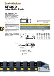
Shaft-Hub ConnectionsTraditional MethodsFig.1: shaft failure due to fatigue crack(heat treated steel C45)Keyway and splined <strong>locking</strong> systems show important disadvantages, in particular underoverload and frequent torque reversal conditions. Connected parts undergo micromovements which cause them damage. The notch of keyway seat is a stress concentratorwhich reduces the fatigue strength. The figures show some fatigue failures fractographs ofnotched shafts (courtesy of ASM International, Metals Handbook, vol 9).Keyways and splines are eliminated byforced fit systems (pressing, heating), wherehigh radial pressures are generated due toshaft - hub interference. A backlash freecoupling is obtained. In addition, sectionsof shafts and bearings can be reduced and,as a consequence, also costs. But this kindof connection shows difficulties during themounting-dismantling steps.Fig.2: fatigue problem caused by torsionFig.3: typical fatigue fracture4LOCKING ASSEMBLIES
Shaft-Hub ConnectionsThe MAV SystemThe MAV Locking Devices meet both the advantages of forced fit systems and simplifiedinstallation-removal. It is based on the wedge principle: the axial load of the screwsgenerates through the tapers a high radial force that locks the parts by friction.The main features of MAV Locking Devices are:· shaft - <strong>locking</strong> device - hub tolerances are sufficient for easy mounting and correctpositioning· high manufacturing precision permits close geometrical tolerances, leading to a wellbalanced coupling, also for high speed conditions· high pressures let high torque to be trasmitted, also in addition with bending moment;fretting corrosion is eliminated· absence of notches results in enhanced static and dynamical strength, leading tolighter and more cost-effective designs· the large variety and the possibility of designing and manufacturing customized unitslet to find the best solution for any kind of specificationsLOCKING ASSEMBLIES 5
MAV Locking Assembliesmain characteristicsMAV seriestorquecapacitybendingcapacityhub contactpressureself-centeringself-<strong>locking</strong>fixed axial hubposition duringtighteningMAV1061 medium medium medium yes yes yesMAV1062 medium medium medium yes yes noMAV2005 medium low high no no yesMAV3003 low - low no no noMAV4061 high high medium yes yes noMAV1008 high high medium yes yes noMAV5061 medium medium low yes yes yesMAV6901 medium medium medium yes yes noMAV6902 medium medium low yes yes yesMAV6002 high high medium yes yes yesMAV6903 medium medium low yes yes yesMAV1261 medium - low yes yes yes6LOCKING ASSEMBLIES
MAV Locking AssembliesThe following series are produced by MAV, but are not included in this catalogue.Furthermore, MAV is specialized in the design and manufacturing of special and customized solutions, even in small batches.MAV seriestorquecapacitybendingcapacityhub contactpressureself-centeringself-<strong>locking</strong>fixed axial hubposition duringtighteningMAV2500 medium medium medium yes yes yesMAV4061L high high medium yes yes noMAV3505 low - low no no noMAV3705 low - low yes yes noMAV4005 low - medium no no yesMAV3061-2-3 medium - medium yes yes yesMAV4071 medium medium medium yes yes yesMAV1800 medium medium low yes yes yesMAV1071 medium medium medium yes yes yesMAV1072 medium medium medium yes yes noMAV7107 low - low yes yes yes / noFor technical features, please visit our website www.mav.it or call +39 0461 845151 or fax +39 0461 845150LOCKING ASSEMBLIES 7
Applications8LOCKING ASSEMBLIES
Steel mill gear connected with special MAV 7061Lever arm connected with MAV 1061Pulley connected with MAV 2005Conveyor pulley connected with MAV 4061Clay mill hub connected with two MAV 1008LOCKING ASSEMBLIES 9
SelectionMAV frictional <strong>locking</strong> <strong>assemblies</strong> provide a keyless, zero backlash connection between shaft andhub, like gears, pulleys, cams, levers, rotors and many others.MAV units are well suited to transmit torque, thrust loads, bending moments and radial loads,separately or simultaneously. Performances listed in this catalogue are calculated without safetyfactor. The user must consider the specific safety factor, which depends on each application.The following criteria are used for selection of the right unit. The selection should be also basedon other specific requirements, like dimensional restrictions, precision of the connection, fixed axialhub position during tightening and others (see characteristics pg. 6 and 7).TorqueWhere T is the peak torque, select a unit where Mt > T, where Mt = torque capacity.Combined loadsWhen the following loads apply:T = peak torqueB = peak bending momentF = peak thrust loadCalculate a resultant torque, according to:Mtc T 2 +d2F . + (2 . B) 22where d = shaft diameterThe selected unit has to meet both requirements:Mt > MtcMb > B, where Mb = bending capacityMb depends on each application.Consult our Technical Dept. for specific information.10LOCKING ASSEMBLIES
Radial loadRadial loads are usually associated with pin or axle connections. They apply perpendicular tothe centerline of the shaft.The radial load generates a contact pressure Prad, according to:FradPradd . Lswhered = shaft diameterLs = shaft – <strong>locking</strong> assembly contact lengthPrad is added and subtracted to the contact pressure Ps provided by <strong>locking</strong> assembly on theshaft. It must be:(Ps + Prad) < Rp 0.2where Rp 0.2 = yield point of shaft material(Ps - Prad) > 0Fitting several units arranged in seriesIn applications where two or more units are installed in series, the total torque capacity Mt totis not linear function of the number of units n. It is calculated as follows:Mt tot = n . Mt . f RSMAV seriesNo. of units (n)2 3 42005 – 1062 – 6902 0.80 0.75 0.704061 0.85 - -1008 0.80 0.75 -3003 0.77 0.62 0.50where f RS = reduction factor,according to table 1.Table 1Shaft and hub verificationLocking <strong>assemblies</strong> exert high contact pressures on both shaft (Ps) and hub (Ph). Size andmaterial of shaft and hub must be selected in order to resist the stress generated by the <strong>locking</strong>assembly and by the applied loads.The following criteria are valid by considering only the contact pressures exerted by the <strong>locking</strong>assembly.The verification of connected components is based on thick walled cylinder theory.LOCKING ASSEMBLIES 11
In case of solid shaft, the material yield point must be greater than shaft contact pressurePs. In case of hollow shaft, the resistance must be calculated by considering the shaft as athick walled cylinder, stressed by external pressure Ps.Hub verification is based on the maximum tangential stress, applied to hub bore. Theminimum hub outer diameter Dem is calculated as follows:DemD .Rp 0.2 + P h. CRp 0.2 - P h. CwhereD = <strong>locking</strong> assembly outer diameter (hub bore diameter)Rp 0.2 = yield point of hub materialC = stress reduction factor (see fig. 1)For a quick calculation, use table 2 which provides the ratio Dem/D.Dem / DHub material yield point Rp 0.2 [MPa]Ph C 140 160 180 200 220 240 260 280 300 320 340 360 380 400 420 440 460 480 5001,0 2,45 2,08 1,87 1,73 1,63 1,56 1,50 1,45 1,41 1,38 1,35 1,33 1,31 1,29 1,27 1,26 1,25 1,24 1,22100 0,8 1,91 1,73 1,61 1,53 1,46 1,41 1,37 1,34 1,31 1,29 1,27 1,25 1,24 1,22 1,21 1,20 1,19 1,18 1,180,6 1,58 1,48 1,41 1,36 1,32 1,29 1,26 1,24 1,22 1,21 1,20 1,18 1,17 1,16 1,15 1,15 1,14 1,13 1,131,0 2,89 2,32 2,04 1,86 1,73 1,64 1,57 1,51 1,47 1,43 1,40 1,37 1,35 1,33 1,31 1,29 1,28 1,26 1,25110 0,8 2,09 1,86 1,71 1,60 1,53 1,47 1,42 1,38 1,35 1,33 1,30 1,28 1,27 1,25 1,24 1,22 1,21 1,20 1,190,6 1,67 1,55 1,47 1,41 1,36 1,33 1,30 1,27 1,25 1,23 1,22 1,20 1,19 1,18 1,17 1,16 1,16 1,15 1,141,0 3,61 2,65 2,24 2,00 1,84 1,73 1,65 1,58 1,53 1,48 1,45 1,41 1,39 1,36 1,34 1,32 1,31 1,29 1,28120 0,8 2,32 2,00 1,81 1,69 1,60 1,53 1,47 1,43 1,39 1,36 1,34 1,31 1,29 1,28 1,26 1,25 1,24 1,22 1,210,6 1,77 1,62 1,53 1,46 1,40 1,36 1,33 1,30 1,28 1,26 1,24 1,22 1,21 1,20 1,19 1,18 1,17 1,16 1,161,0 5,20 3,11 2,49 2,17 1,97 1,83 1,73 1,65 1,59 1,54 1,50 1,46 1,43 1,40 1,38 1,36 1,34 1,32 1,30130 0,8 2,60 2,17 1,93 1,78 1,67 1,59 1,53 1,48 1,44 1,40 1,37 1,35 1,32 1,30 1,29 1,27 1,26 1,25 1,240,6 1,88 1,70 1,59 1,51 1,45 1,40 1,36 1,33 1,30 1,28 1,26 1,25 1,23 1,22 1,21 1,20 1,19 1,18 1,171,0 3,87 2,83 2,38 2,12 1,95 1,83 1,73 1,66 1,60 1,55 1,51 1,47 1,44 1,41 1,39 1,37 1,35 1,33140 0,8 3,00 2,38 2,07 1,88 1,75 1,66 1,59 1,53 1,48 1,44 1,41 1,38 1,35 1,33 1,31 1,30 1,28 1,27 1,260,6 2,00 1,79 1,66 1,56 1,50 1,44 1,40 1,36 1,33 1,31 1,29 1,27 1,25 1,24 1,22 1,21 1,20 1,19 1,181,0 5,57 3,32 2,65 2,30 2,08 1,93 1,82 1,73 1,66 1,61 1,56 1,52 1,48 1,45 1,43 1,40 1,38 1,36150 0,8 3,61 2,65 2,24 2,00 1,84 1,73 1,65 1,58 1,53 1,48 1,45 1,41 1,39 1,36 1,34 1,32 1,31 1,29 1,280,6 2,14 1,89 1,73 1,62 1,54 1,48 1,43 1,40 1,36 1,34 1,31 1,29 1,27 1,26 1,24 1,23 1,22 1,21 1,201,0 4,12 3,00 2,52 2,24 2,05 1,91 1,81 1,73 1,67 1,61 1,57 1,53 1,49 1,46 1,44 1,41 1,39160 0,8 4,73 3,00 2,43 2,13 1,94 1,81 1,71 1,64 1,58 1,53 1,49 1,45 1,42 1,39 1,37 1,35 1,33 1,31 1,300,6 2,32 2,00 1,81 1,69 1,60 1,53 1,47 1,43 1,39 1,36 1,34 1,31 1,29 1,28 1,26 1,25 1,24 1,22 1,211,0 5,92 3,51 2,79 2,42 2,19 2,02 1,90 1,81 1,73 1,67 1,62 1,57 1,54 1,50 1,47 1,45 1,42170 0,8 8,31 3,51 2,68 2,29 2,06 1,90 1,79 1,70 1,63 1,57 1,53 1,49 1,45 1,42 1,40 1,38 1,36 1,34 1,320,6 2,52 2,13 1,90 1,76 1,65 1,57 1,51 1,46 1,42 1,39 1,36 1,34 1,32 1,30 1,28 1,27 1,25 1,24 1,231,0 4,36 3,16 2,65 2,35 2,14 2,00 1,89 1,80 1,73 1,67 1,62 1,58 1,54 1,51 1,48 1,46180 0,8 4,36 3,00 2,48 2,19 2,00 1,87 1,77 1,69 1,62 1,57 1,53 1,49 1,46 1,43 1,40 1,38 1,36 1,340,6 2,78 2,27 2,00 1,83 1,71 1,62 1,56 1,50 1,46 1,42 1,39 1,36 1,34 1,32 1,30 1,28 1,27 1,26 1,251,0 6,24 3,70 2,93 2,54 2,29 2,11 1,98 1,88 1,80 1,73 1,68 1,63 1,59 1,55 1,52 1,49190 0,8 6,24 3,44 2,71 2,34 2,11 1,95 1,84 1,75 1,68 1,62 1,57 1,53 1,49 1,46 1,43 1,41 1,39 1,370,6 3,13 2,44 2,11 1,91 1,78 1,68 1,60 1,54 1,49 1,45 1,42 1,39 1,36 1,34 1,32 1,30 1,29 1,27 1,261,0 4,58 3,32 2,77 2,45 2,24 2,08 1,96 1,87 1,80 1,73 1,68 1,63 1,59 1,56 1,53200 0,8 4,12 3,00 2,52 2,24 2,05 1,91 1,81 1,73 1,67 1,61 1,57 1,53 1,49 1,46 1,44 1,41 1,390,6 3,61 2,65 2,24 2,00 1,84 1,73 1,65 1,58 1,53 1,48 1,45 1,41 1,39 1,36 1,34 1,32 1,31 1,29 1,28Table 212LOCKING ASSEMBLIES
If the hub has a different configuration, considerthe most similar shape or the worst condition. OurTechnical Dept. is at your disposal for technicalassistance.Fig. 1Stress reduction factor Cvalid for all seriesB < 1.5xH 1.5xH < B < 2xH B > 2xH1 0.8 0.6Self-centering and self-<strong>locking</strong> unitsMaterialSELF-CENTERING units provide an excellent centering of the connection. Concentricity andperpendicularity range from 0.02 mm to 0.05 mm. Self-centering characteristic depends onlength and taper angle, manufacturing process and proper installation.If the <strong>locking</strong> assembly is not self-centering, a pre-centering hub section is needed in order toobtain an excellent centering of the connection.SELF-LOCKING units ensure the transmission of loads even in case of loosening of the screws. Inaddition, the screws are not subject to dynamic stress (typical when bending moment applies),which causes fatigue failure. Self-<strong>locking</strong> characteristic depends on taper angle.Removal of self-<strong>locking</strong> units is obtained by means of integrated push-off threads. Removal ofself-releasing units is obtained by loosening the <strong>locking</strong> screws.MAV <strong>locking</strong> <strong>assemblies</strong> are manufactured from carbon and heat treated alloy steels. In orderto improve corrosion resistance, all units are available in different grades of stainless steel(reduction of performances approx. 50%), as well as supplied with different surface coatings likezinc plating, nickel plating and phosphate treatment.LubricationLocking <strong>assemblies</strong> are lubricated with ordinary machine oil. Stainless steel units are lubricatedwith food grade oil, quality H-1 according to FDA. Shaft and hub must be oiled as well. Do notuse low friction lubricants (ex. Molybdenum Disulfide based grease) which strongly reduce theperformances of the units.Temperature influenceWorking temperature ranges from –20°C to +150°C. Locking <strong>assemblies</strong> work correctly as longas temperature changes apply equally to shaft and hub. Different materials must be used if theconnection works in temperatures out of the above mentioned range.LOCKING ASSEMBLIES 13
MAV 1061Standard SeriesDIMENSIONS SCREWS PERFORMANCESWEIGHTkgdmm x D D1 L2 L1 L Ma Mt Fax Ps Phsizemm mm mm mm mm Nm Nm kN MPa MPa14 x 28 32,0 17,0 20,5 24,5 M 4 5 68 10 132 66 0,0715 x 28 32,0 17,0 20,5 24,5 M 4 5 73 10 123 66 0,0616 x 32 37,0 18,0 21,5 25,5 M 4 5 78 10 115 58 0,0918 x 47 52,0 22,5 28,5 34,5 M 6 17 250 28 241 92 0,3019 x 47 52,0 22,5 28,5 34,5 M 6 17 260 28 229 92 0,3020 x 47 52,0 22,5 28,5 34,5 M 6 17 280 28 217 92 0,3022 x 47 52,0 22,5 28,5 34,5 M 6 17 310 28 197 92 0,3024 x 50 56,5 22,5 28,5 34,5 M 6 17 400 33 217 104 0,3025 x 50 56,5 22,5 28,5 34,5 M 6 17 420 33 209 104 0,3028 x 55 61,5 22,5 28,5 34,5 M 6 17 470 33 186 95 0,4030 x 55 61,5 22,5 28,5 34,5 M 6 17 500 33 174 95 0,3032 x 60 66,5 22,5 28,5 34,5 M 6 17 710 45 217 116 0,4035 x 60 66,5 22,5 28,5 34,5 M 6 17 780 45 199 116 0,4038 x 65 71,5 22,5 28,5 34,5 M 6 17 850 45 183 107 0,5040 x 65 71,5 22,5 28,5 34,5 M 6 17 890 45 174 107 0,4042 x 75 83,5 26,5 34,5 42,5 M 8 41 1˙510 72 227 127 0,8045 x 75 83,5 26,5 34,5 42,5 M 8 41 1˙620 72 212 127 0,7048 x 80 88,5 26,5 34,5 42,5 M 8 41 1˙730 72 199 119 0,8050 x 80 88,5 26,5 34,5 42,5 M 8 41 1˙800 72 191 119 0,8055 x 85 93,5 26,5 34,5 42,5 M 8 41 2˙260 82 198 128 0,8060 x 90 98,0 26,5 34,5 42,5 M 8 41 2˙470 82 182 121 0,9065 x 95 102,0 26,5 34,5 42,5 M 8 41 3˙010 93 189 129 0,9070 x 110 119,0 30,5 40,5 50,5 M 10 83 4˙730 135 213 136 1,7075 x 115 124,0 30,5 40,5 50,5 M 10 83 5˙070 135 199 130 1,8080 x 120 129,0 30,5 40,5 50,5 M 10 83 5˙410 135 187 124 1,9085 x 125 134,0 30,5 40,5 50,5 M 10 83 6˙460 152 198 134 2,0090 x 130 139,0 30,5 40,5 50,5 M 10 83 6˙840 152 187 129 2,0095 x 135 144,0 30,5 40,5 50,5 M 10 83 8˙020 169 197 138 2,10100 x 145 154,0 33,0 45,0 57,0 M 12 145 10˙100 202 206 142 2,80110 x 155 164,0 33,0 45,0 57,0 M 12 145 11˙100 202 187 133 3,00120 x 165 174,0 33,0 45,0 57,0 M 12 145 13˙600 227 193 140 3,30130 x 180 189,0 41,0 55,0 69,0 M 14 230 19˙800 305 183 132 4,70140 x 190 199,0 41,0 55,0 69,0 M 14 230 21˙400 305 170 125 5,20150 x 200 209,0 41,0 55,0 69,0 M 14 230 25˙400 339 176 132 5,50160 x 210 219,0 41,0 55,0 69,0 M 14 230 29˙900 373 182 139 5,80170 x 225 234,0 51,0 65,0 79,0 M 14 230 34˙600 407 144 109 8,10180 x 235 244,0 51,0 65,0 79,0 M 14 230 36˙600 407 136 104 8,50190 x 250 259,0 51,0 65,0 79,0 M 14 230 48˙300 509 161 123 9,80200 x 260 269,0 51,0 65,0 79,0 M 14 230 50˙900 509 153 118 10,20220 x 285 292,0 57,0 73,0 89,0 M 16 355 61˙300 558 134 104 13,70240 x 305 314,0 57,0 73,0 89,0 M 16 355 83˙600 697 154 121 14,80260 x 325 334,0 57,0 73,0 89,0 M 16 355 109˙000 836 171 137 15,80280 x 355 364,0 67,0 85,0 103,0 M 18 485 126˙000 897 142 112 23,40300 x 375 384,0 67,0 85,0 103,0 M 18 485 151˙000 1˙010 149 119 24,80320 x 405 414,0 82,0 102,0 122,0 M 20 690 209˙000 1˙310 146 116 35,00340 x 425 434,0 82,0 102,0 122,0 M 20 690 259˙000 1˙530 161 129 37,00360 x 455 464,0 94,0 116,0 138,0 M 22 930 292˙000 1˙620 139 110 50,50380 x 475 484,0 94,0 116,0 138,0 M 22 930 359˙000 1˙890 153 123 53,10400 x 495 504,0 94,0 116,0 138,0 M 22 930 378˙000 1˙890 146 118 56,50Example of order: MAV 1061 50 x 80Features• Medium capacity• Self-centering, self-<strong>locking</strong>• Fixed axial hub position during tightening(MAV 1061 only)• Single taper design• Tolerances: shaft h8; hub bore H8• Surface finish of shaft and hub bore Ra < 3.2 μmApplication examplesSimultaneousconnectionof chain sprocketand conveyorpulley14LOCKING ASSEMBLIES
Standard Series MAV 1062Example of order: MAV 1062 50 x 80Composition• Slotted inner ring, with integratedpush-off threads• Slotted outer ring• Set of socket head cap screws, grade 12.9Componentsouter ringinner ringscrewsCode:Ma: screws tightening torqueMt: transmissible torque with Fax=O kNFax: transmissible axial load with Mt=O NmPs: contact pressure on shaftPh: contact pressure in hub boredmm x DmmDIMENSIONS SCREWS PERFORMANCESL1mmLmmsizeMaNmMtNmFaxkNPsMPaPhMPaWEIGHTkg14 x 32 21,5 25,5 M 4 5 108 15 209 91 0,0915 x 32 21,5 25,5 M 4 5 116 15 195 91 0,0916 x 32 21,5 25,5 M 4 5 123 15 183 91 0,0818 x 47 28,5 34,5 M 6 14 330 36 314 120 0,3019 x 47 28,5 34,5 M 6 14 340 36 297 120 0,3020 x 47 28,5 34,5 M 6 14 360 36 283 120 0,3022 x 47 28,5 34,5 M 6 14 400 36 257 120 0,2024 x 50 28,5 34,5 M 6 14 520 43 283 136 0,3025 x 50 28,5 34,5 M 6 14 540 43 271 136 0,3028 x 55 28,5 34,5 M 6 14 610 43 242 123 0,3030 x 55 28,5 34,5 M 6 14 650 43 226 123 0,3032 x 60 28,5 34,5 M 6 14 930 58 283 151 0,4035 x 60 28,5 34,5 M 6 14 1˙010 58 258 151 0,3038 x 65 28,5 34,5 M 6 14 1˙100 58 238 139 0,4040 x 65 28,5 34,5 M 6 14 1˙160 58 226 139 0,4042 x 75 34,5 42,5 M 8 35 2˙040 97 307 172 0,7045 x 75 34,5 42,5 M 8 35 2˙190 97 287 172 0,6048 x 80 34,5 42,5 M 8 35 2˙340 97 269 161 0,7050 x 80 34,5 42,5 M 8 35 2˙430 97 258 161 0,7055 x 85 34,5 42,5 M 8 35 3˙060 111 268 174 0,8060 x 90 34,5 42,5 M 8 35 3˙340 111 246 164 0,8065 x 95 34,5 42,5 M 8 35 4˙070 125 255 175 0,9070 x 110 40,5 50,5 M 10 69 6˙230 178 281 179 1,6075 x 115 40,5 50,5 M 10 69 6˙680 178 262 171 1,6080 x 120 40,5 50,5 M 10 69 7˙120 178 246 164 1,7085 x 125 40,5 50,5 M 10 69 8˙510 200 261 177 1,8090 x 130 40,5 50,5 M 10 69 9˙020 200 246 170 1,9095 x 135 40,5 50,5 M 10 69 10˙570 223 259 182 2,00100 x 145 45,0 57,0 M 12 120 13˙200 265 270 186 2,60110 x 155 45,0 57,0 M 12 120 14˙600 265 245 174 2,90120 x 165 45,0 57,0 M 12 120 17˙900 298 253 184 3,10130 x 180 55,0 69,0 M 14 190 26˙000 400 240 173 4,50140 x 190 55,0 69,0 M 14 190 28˙000 400 223 164 5,00150 x 200 55,0 69,0 M 14 190 33˙300 444 231 173 5,20160 x 210 55,0 69,0 M 14 190 39˙100 488 238 181 5,60170 x 225 65,0 79,0 M 14 190 45˙300 533 189 143 7,70180 x 235 65,0 79,0 M 14 190 48˙000 533 178 137 8,10190 x 250 65,0 79,0 M 14 190 63˙300 666 211 161 9,30200 x 260 65,0 79,0 M 14 190 66˙600 666 201 154 9,90220 x 285 73,0 89,0 M 16 295 81˙000 736 178 137 13,30240 x 305 73,0 89,0 M 16 295 110˙000 920 203 160 14,20260 x 325 73,0 89,0 M 16 295 144˙000 1˙104 225 180 15,30280 x 355 85,0 103,0 M 18 405 166˙000 1˙187 187 148 22,70300 x 375 85,0 103,0 M 18 405 200˙000 1˙340 197 157 24,30320 x 405 102,0 122,0 M 20 580 279˙000 1˙750 196 155 34,10340 x 425 102,0 122,0 M 20 580 346˙000 2˙040 215 172 36,00360 x 455 116,0 138,0 M 22 780 388˙000 2˙160 185 146 49,40380 x 475 116,0 138,0 M 22 780 478˙000 2˙520 204 163 51,90400 x 495 116,0 138,0 M 22 780 503˙000 2˙520 194 157 55,30LOCKING ASSEMBLIES 15
MAV 2005Standard SeriesDIMENSIONS SCREWS PERFORMANCESdmm x DmmL1mmLmm size MaNmMtNmFaxkNPsMPaPhMPaWEIGHTkg18 x 47 20 26 M 6 17 300 33 332 127 0,219 x 47 20 26 M 6 17 310 33 314 127 0,220 x 47 20 26 M 6 17 330 33 298 127 0,222 x 47 20 26 M 6 17 360 33 271 127 0,224 x 50 20 26 M 6 17 440 37 280 134 0,225 x 50 20 26 M 6 17 460 36 269 134 0,228 x 55 20 26 M 6 17 560 40 266 136 0,330 x 55 20 26 M 6 17 600 40 249 136 0,332 x 60 20 26 M 6 17 770 48 280 149 0,335 x 60 20 26 M 6 17 830 48 256 149 0,338 x 65 20 26 M 6 17 1˙050 55 275 161 0,340 x 65 20 26 M 6 17 1˙100 55 261 161 0,342 x 75 24 32 M 8 41 1˙830 87 336 188 0,645 x 75 24 32 M 8 41 1˙950 87 314 188 0,548 x 80 24 32 M 8 41 2˙080 87 294 176 0,650 x 80 24 32 M 8 41 2˙160 86 282 176 0,655 x 85 24 32 M 8 41 2˙750 100 300 194 0,660 x 90 24 32 M 8 41 2˙990 100 275 183 0,763 x 95 24 32 M 8 41 3˙570 113 299 198 0,765 x 95 24 32 M 8 41 3˙680 113 290 198 0,770 x 110 28 38 M 10 83 5˙650 162 321 204 1,275 x 115 28 38 M 10 83 6˙030 161 300 196 1,380 x 120 28 38 M 10 83 6˙410 160 281 187 1,485 x 125 28 38 M 10 83 7˙750 182 302 206 1,490 x 130 28 38 M 10 83 8˙180 182 286 198 1,595 x 135 28 38 M 10 83 9˙680 204 304 214 1,6100 x 145 33 45 M 12 145 11˙700 234 307 212 2,1110 x 155 33 45 M 12 145 12˙800 232 279 198 2,3120 x 165 33 45 M 12 145 15˙900 264 293 213 2,5130 x 180 38 50 M 12 145 21˙400 329 258 187 3,5140 x 190 38 50 M 12 145 25˙200 360 264 194 3,8150 x 200 38 50 M 12 145 29˙300 391 269 201 4,0160 x 210 38 50 M 12 145 33˙700 422 273 208 4,2170 x 225 44 58 M 14 230 41˙200 485 265 200 5,7180 x 235 44 58 M 14 230 47˙400 527 273 209 6,0190 x 250 52 66 M 14 230 58˙200 613 249 190 8,2200 x 260 52 66 M 14 230 65˙400 655 254 195 8,5220 x 285 56 72 M 16 355 85˙100 774 252 195 10,8240 x 305 56 72 M 16 355 107˙000 888 267 210 11,9260 x 325 56 72 M 16 355 130˙000 1˙001 279 223 12,8280 x 355 66 84 M 18 485 158˙000 1˙128 245 193 19,3300 x 375 66 84 M 18 485 190˙000 1˙264 257 206 20,6Features• Medium capacity• Not self-centering, not self-<strong>locking</strong> (self-releasing)• Fixed axial hub position during tightening• Two thrust rings with double taper design• Low axial dimension• Tolerances: shaft h7-h11; hub bore H7-H11• Surface finish of shaft and hub bore Ra < 3.2 μmApplication examplesgear wheel connection16LOCKING ASSEMBLIES
Standard Series MAV 2005LL1ØdComposition• Slotted inner ring• Slotted outer ringØDExample of order: MAV 2005 50 x 80• Double taper front thrust ring, with integratedpull-out threads• Double taper rear thrust ring• Set of socket head cap screws, grade 12.9.Zinc plated screws indicate the position of pull-out threadsComponentsthrustringinnerringouter ringthrust ringscrewsDIMENSIONS SCREWS PERFORMANCESdmm x DmmL1mmLmm size MaNmMtNmFaxkNPsMPaPhMPaWEIGHTkg320 x 405 78 98 M 20 690 260˙000 1˙627 259 205 29,4340 x 425 78 98 M 20 690 275˙000 1˙620 244 195 31,0360 x 455 90 112 M 22 930 356˙000 1˙980 242 192 43,0380 x 475 90 112 M 22 930 375˙000 1˙973 230 184 45,0400 x 495 90 112 M 22 930 393˙000 1˙967 218 176 47,0420 x 515 90 112 M 22 930 458˙000 2˙179 231 188 49,0440 x 545 102 126 M 24 1˙200 562˙000 2˙555 227 183 65,0460 x 565 102 126 M 24 1˙200 586˙000 2˙548 217 177 67,0480 x 585 102 126 M 24 1˙200 640˙000 2˙668 218 179 71,0500 x 605 102 126 M 24 1˙200 697˙000 2˙788 220 181 72,0520 x 630 102 126 M 24 1˙200 740˙000 2˙845 216 178 80,0540 x 650 102 126 M 24 1˙200 766˙000 2˙838 208 173 82,0560 x 670 102 126 M 24 1˙200 846˙000 3˙020 214 179 84,0580 x 690 102 126 M 24 1˙200 910˙000 3˙139 215 181 87,0600 x 710 102 126 M 24 1˙200 940˙000 3˙133 208 176 91,0620 x 730 102 126 M 24 1˙200 1˙008˙000 3˙251 209 178 93,0640 x 750 102 126 M 24 1˙200 1˙078˙000 3˙370 210 180 96,0660 x 770 102 126 M 24 1˙200 1˙151˙000 3˙488 212 181 99,0680 x 790 102 126 M 24 1˙200 1˙184˙000 3˙481 205 177 102,0700 x 810 102 126 M 24 1˙200 1˙303˙000 3˙723 214 185 104,0720 x 830 102 126 M 24 1˙200 1˙338˙000 3˙717 208 180 107,0740 x 850 102 126 M 24 1˙200 1˙419˙000 3˙834 209 182 110,0760 x 870 102 126 M 24 1˙200 1˙501˙000 3˙951 210 184 112,0780 x 890 102 126 M 24 1˙200 1˙562˙000 4˙006 208 182 116,0800 x 910 102 126 M 24 1˙200 1˙625˙000 4˙061 206 181 118,0820 x 930 102 126 M 24 1˙200 1˙713˙000 4˙178 207 182 121,0840 x 950 102 126 M 24 1˙200 1˙804˙000 4˙294 208 184 124,0860 x 970 102 126 M 24 1˙200 1˙897˙000 4˙411 209 185 127,0880 x 990 102 126 M 24 1˙200 1˙992˙000 4˙527 210 186 129,0900 x 1˙010 102 126 M 24 1˙200 2˙062˙000 4˙581 208 185 132,0920 x 1˙030 102 126 M 24 1˙200 2˙133˙000 4˙636 206 184 135,0940 x 1˙050 102 126 M 24 1˙200 2˙233˙000 4˙752 207 185 138,0960 x 1˙070 102 126 M 24 1˙200 2˙336˙000 4˙867 208 187 140,0980 x 1˙090 102 126 M 24 1˙200 2˙412˙000 4˙922 206 185 143,01˙000 x 1˙110 102 126 M 24 1˙200 2˙488˙000 4˙976 205 184 146,0Code:Ma: screws tightening torqueMt: transmissible torque with Fax=O kNFax: transmissible axial load with Mt=O NmPs: contact pressure on shaftPh: contact pressure in hub boreLOCKING ASSEMBLIES 17
MAV 3003Standard SeriesDIMENSIONS PERFORMANCES XWEIGHTkgdmm x D L Ca Cb Mt Fax Ps Ph 1 2 3mm mm kN kN Nm kN MPa MPa mm mm mm6 x 9 4,5 0,0 4,7 3 1,0 120 80 2 2 3 0,0017 x 10 4,5 0,0 5,4 4 1,2 120 84 2 2 3 0,0018 x 11 4,5 0,0 6,2 5 1,3 120 87 2 2 3 0,0029 x 12 4,5 7,6 7,0 7 1,5 120 90 2 2 3 0,00210 x 13 4,5 7,0 7,8 8 1,7 120 92 2 2 3 0,00212 x 15 4,5 7,0 9,3 12 2,0 120 96 2 2 3 0,00213 x 16 4,5 6,6 10,1 14 2,2 120 98 2 2 3 0,00214 x 18 6,3 11,2 15,5 23 3,4 120 93 3 3 4 0,00415 x 19 6,3 10,6 16,7 27 3,6 120 95 3 3 4 0,00516 x 20 6,3 10,0 17,8 31 3,8 120 96 3 3 4 0,00517 x 21 6,3 9,5 18,9 35 4,1 120 97 3 3 4 0,00518 x 22 6,3 9,1 20,0 39 4,3 120 98 3 3 4 0,00619 x 24 6,3 12,7 21,1 43 4,6 120 95 3 3 4 0,00720 x 25 6,3 12,2 22,2 48 4,8 120 96 3 3 4 0,00822 x 26 6,3 9,3 24,4 58 5,3 120 102 3 3 4 0,00724 x 28 6,3 8,6 26,6 69 5,8 120 103 3 3 4 0,00725 x 30 6,3 10,1 27,8 75 6,0 120 100 3 3 4 0,01028 x 32 6,3 7,5 31,1 94 6,7 120 105 3 3 4 0,01030 x 35 6,3 8,6 33,3 108 7,2 120 103 3 3 4 0,01032 x 36 6,3 7,8 35,5 123 7,7 120 107 3 3 4 0,01035 x 40 7,0 9,9 44,0 170 9,5 120 105 3 3 4 0,02036 x 42 7,0 11,4 45,2 180 9,8 120 103 3 3 4 0,02038 x 44 7,0 10,9 47,8 200 10,3 120 104 3 3 4 0,02040 x 45 8,0 13,6 55,3 240 11,9 120 107 3 4 5 0,02042 x 48 8,0 15,4 58,1 260 12,5 120 105 3 4 5 0,03045 x 52 10,0 23,8 81,1 390 17,5 120 104 3 4 5 0,04048 x 55 10,0 22,6 86,5 450 18,7 120 105 3 4 5 0,04050 x 57 10,0 21,8 90,1 490 19,5 120 105 3 4 5 0,04055 x 62 10,0 21,4 99,1 590 21,4 120 106 3 4 5 0,05056 x 64 12,0 28,7 122,0 740 26,3 120 105 3 4 5 0,07060 x 68 12,0 27,0 130,7 850 28,2 120 106 3 4 5 0,07063 x 71 12,0 25,8 137,3 930 29,6 120 106 3 4 5 0,08065 x 73 12,0 25,1 141,6 990 30,6 120 107 3 4 5 0,08070 x 79 14,0 30,6 178,9 1˙350 38,6 120 106 3 5 6 0,10071 x 80 14,0 30,2 181,5 1˙390 39,2 120 107 3 5 6 0,10075 x 84 14,0 32,2 191,7 1˙550 41,4 120 107 3 5 6 0,10080 x 91 17,0 44,4 251,4 2˙170 54,3 120 105 4 5 6 0,20085 x 96 17,0 44,9 267,1 2˙450 57,7 120 106 4 5 6 0,20090 x 101 17,0 42,6 282,8 2˙750 61,1 120 107 4 5 6 0,20095 x 10⁶ 17,0 40,5 298,5 3˙060 64,5 120 108 4 5 6 0,200Features• Low capacity• Not self-centering, not self-<strong>locking</strong> (self-releasing)• Single taper design• Low axial and radial dimensions• Thrust ring is needed (not supplied by MAV)• Slotted execution also available• Tolerances (for shaft dia. ≤ 38mm): shaft h6; hub bore H7• Tolerances (for shaft dia. > 38mm): shaft h8; hub bore H8• Surface finish of shaft and hub bore Ra < 0.8 μmComponentsouter ringinner ring18LOCKING ASSEMBLIES
Standard Series MAV 3003LØdØDExample of order: MAV 3003 50 x 57Composition• Inner ring• Outer ringApplication examplesConnection of seal and flangeof a pneumatic cylinderDIMENSIONS PERFORMANCES XWEIGHTkgdmm x D L Ca Cb Mt Fax Ps Ph 1 2 3mm mm kN kN Nm kN MPa MPa mm mm mm100 x 114 21,0 60,1 392 4230 84,6 120 105 4 6 7 0,4110 x 124 21,0 60,8 431 5120 93,1 120 106 4 6 7 0,4120 x 134 21,0 56,4 470 6090 101,5 120 107 4 6 7 0,5130 x 148 28,0 94,3 689 9˙670 148,8 120 105 5 7 9 0,8140 x 158 28,0 88,2 742 11˙200 160,2 120 106 5 7 9 0,9150 x 168 28,0 82,8 795 12˙900 171,7 120 107 5 7 9 1,0160 x 178 28,0 78,0 848 14˙700 183,1 120 108 5 7 9 1,0170 x 191 33,0 110,0 1˙070 19˙600 230,7 120 107 6 8 10 1,5180 x 201 33,0 104,7 1˙130 22˙000 244,3 120 107 6 8 10 1,6190 x 211 33,0 105,3 1˙190 24˙500 257,9 120 108 6 8 10 1,7200 x 224 38,0 131,7 1˙460 31˙500 314,9 120 107 6 8 11 2,3210 x 234 38,0 125,9 1˙530 34˙700 330,6 120 108 6 8 11 2,5220 x 244 38,0 120,6 1˙600 38˙100 346,3 120 108 6 8 11 2,6230 x 257 43,0 149,4 1˙900 47˙300 411,0 120 107 6 9 12 3,4240 x 267 43,0 143,9 1˙990 51˙500 428,9 120 108 6 9 12 3,6250 x 280 48,0 169,6 2˙300 62˙200 497,6 120 107 7 10 13 4,6260 x 290 48,0 173,1 2˙400 67˙300 517,5 120 108 7 10 13 4,8270 x 300 48,0 167,2 2˙490 72˙600 537,4 120 108 7 10 13 5,0280 x 313 53,0 202,2 2˙870 86˙900 620,7 120 107 7 11 14 6,3290 x 323 53,0 196,1 2˙980 93˙200 642,8 120 108 7 11 14 6,5300 x 333 53,0 190,4 3˙080 99˙800 665,0 120 108 7 11 14 6,7320 x 360 65,0 271,6 3˙960 137˙000 854,1 120 107 10 15 20 10,7340 x 380 65,0 257,0 4˙200 154˙000 907,5 120 107 10 15 20 11,4360 x 400 65,0 245,9 4˙450 173˙000 960,9 120 108 10 15 20 12,0380 x 420 65,0 234,5 4˙700 193˙000 1˙014,3 120 109 10 15 20 12,7400 x 440 65,0 224,1 4˙940 214˙000 1˙067,6 120 109 10 15 20 13,2420 x 460 65,0 224,7 5˙190 235˙000 1˙121,0 120 110 10 15 20 13,8440 x 480 65,0 215,1 5˙440 258˙000 1˙174,4 120 110 10 15 20 14,5460 x 500 65,0 209,6 5˙690 282˙000 1˙227,8 120 110 13 19 26 15,0480 x 520 65,0 201,7 5˙930 308˙000 1˙281,2 120 111 13 19 26 15,5500 x 540 65,0 194,4 6˙180 334˙000 1˙334,5 120 111 13 19 26 16,5Code:Ma: screws tightening torqueMt: transmissible torque with Fax=O kNFax: transmissible axial load with Mt=O NmCa: assembling loadCb: <strong>locking</strong> loadPs: contact pressure on shaftPh: contact pressure in hub boreX: thrust flange - hub distanceLOCKING ASSEMBLIES 19
MAV 4061Standard SeriesLL1ØdØDExample of order: MAV 4061 50 x 80Features• High capacity• Self-centering, self-<strong>locking</strong>• Two thrust rings with single taper design• Tolerances: shaft h8; hub bore H8Composition• Slotted front thrust ring, with integrated push-off holes• Slotted rear thrust ring• Slotted outer ring, with integrated push-off threads• Set of socket head cap screws, grade 12.9• Surface finish of shaft and hub bore Ra < 3.2 μmApplication examplesComponentsthrustringouter ringthrust ringSimultaneous connection of two shafts with hollow shaft and hubwith MAV 4061 and shrink disc MAV 2008screws20LOCKING ASSEMBLIES
Standard Series MAV 4061DIMENSIONS SCREWS PERFORMANCESdmm x D L1 LMa Mt Fax Ps Phsizemm mm mm Nm Nm kN MPa MPa24 x 55 40 46 M 6 17 800 67 308 134 0,425 x 55 40 46 M 6 17 840 67 295 134 0,428 x 55 40 46 M 6 17 940 67 264 134 0,430 x 55 40 46 M 6 17 1˙000 67 246 134 0,432 x 60 54 60 M 6 17 1˙200 78 190 101 0,635 x 60 54 60 M 6 17 1˙400 78 174 101 0,638 x 75 54 62 M 8 41 2˙700 144 296 150 1,040 x 75 54 62 M 8 41 2˙900 144 281 150 1,042 x 75 54 62 M 8 41 3˙000 144 268 150 1,045 x 75 54 62 M 8 41 3˙200 144 250 150 0,948 x 80 66 74 M 8 41 4˙000 165 207 124 1,350 x 80 66 74 M 8 41 4˙100 165 198 124 1,255 x 85 66 74 M 8 41 5˙100 185 203 131 1,360 x 90 66 74 M 8 41 6˙200 206 207 138 1,465 x 95 66 74 M 8 41 6˙700 206 191 131 1,570 x 110 80 90 M 10 83 11˙800 338 229 145 2,875 x 115 80 90 M 10 83 12˙700 338 213 139 3,080 x 120 80 90 M 10 83 14˙900 372 220 147 3,185 x 125 80 90 M 10 83 15˙800 372 207 141 3,390 x 130 80 90 M 10 83 18˙200 405 213 148 3,595 x 135 80 90 M 10 83 19˙300 405 202 142 3,6100 x 145 102 114 M 12 145 27˙700 555 210 145 5,6110 x 155 102 114 M 12 145 33˙300 605 209 148 6,1120 x 165 102 114 M 12 145 42˙400 706 223 162 6,5130 x 180 116 130 M 14 230 53˙700 826 201 145 9,0140 x 190 116 130 M 14 230 67˙400 963 217 160 9,5150 x 200 116 130 M 14 230 77˙400 1˙030 217 163 10,1160 x 210 116 130 M 14 230 88˙100 1˙100 217 166 10,6170 x 225 149 165 M 16 355 111˙000 1˙310 186 141 16,1180 x 235 149 165 M 16 355 126˙000 1˙410 188 144 16,9190 x 250 149 165 M 16 355 142˙000 1˙500 190 145 19,6200 x 260 149 165 M 16 355 150˙000 1˙500 181 139 20,5220 x 285 150 166 M 16 355 185˙000 1˙690 185 143 24,5240 x 305 150 166 M 16 355 225˙000 1˙870 188 148 26,5260 x 325 150 166 M 16 355 256˙000 1˙970 182 146 28,5280 x 355 177 197 M 20 690 370˙000 2˙640 190 150 42,5300 x 375 177 197 M 20 690 440˙000 2˙940 197 157 46,5320 x 405 177 197 M 20 690 493˙000 3˙080 194 153 56,0340 x 425 177 197 M 20 690 549˙000 3˙230 191 153 59,5360 x 455 203 225 M 22 930 680˙000 3˙780 183 145 80,0380 x 475 203 225 M 22 930 752˙000 3˙960 182 145 84,5400 x 495 203 225 M 22 930 864˙000 4˙320 188 152 88,0420 x 515 203 225 M 22 930 907˙000 4˙320 179 146 92,0440 x 535 203 225 M 22 930 950˙000 4˙320 171 141 96,0460 x 555 203 225 M 22 930 993˙000 4˙320 164 136 100,5480 x 575 203 225 M 22 930 1˙209˙000 5˙040 183 153 103,0500 x 595 203 225 M 22 930 1˙260˙000 5˙040 176 148 107,5520 x 615 203 225 M 22 930 1˙404˙000 5˙400 181 153 111,0540 x 635 203 225 M 22 930 1˙458˙000 5˙400 174 148 114,0560 x 655 203 225 M 22 930 1˙613˙000 5˙760 179 153 118,5580 x 675 203 225 M 22 930 1˙670˙000 5˙760 173 149 123,0600 x 695 203 225 M 22 930 1˙782˙000 5˙940 173 149 128,0WEIGHTkgPinion gear connected with MAV 4061. Theresisting ring is used to compensate the pressuregenerated by the <strong>locking</strong> assembly in thezone adjacent to the pinion gear.Code:Ma: screws tightening torqueMt: transmissible torque with Fax=O kNFax: transmissible axial load with Mt=O NmPs: contact pressure on shaftPh: contact pressure in hub boreLOCKING ASSEMBLIES 21
MAV 1008Standard SeriesExample of order: MAV 1008 100 x 145Features• High capacity• Self-centering, self-<strong>locking</strong>• Two thrust rings with single taper design• Tolerances: shaft h7-h11; hub bore H7-H11Composition• Slotted front thrust ring, with integrated push-off holes• Slotted rear thrust ring• Slotted outer ring, with integrated push-off threads• Set of socket head cap screws, grade 12.9• Surface finish of shaft and hub bore Ra < 3.2 μmApplication examplesComponentsthrustringouter ringthrust ringBrake disc connected with MAV 1008 and flangescrews22LOCKING ASSEMBLIES
Standard Series MAV 1008DIMENSIONI SCREWS PERFORMANCESdmm x DmmL1mmLmmsizeMaNmMtNmFaxkNPsMPaPhMPaWEIGHTkg70 x 110 62 72 M 10 83 7˙300 208 197 125 2,375 x 115 62 72 M 10 83 7˙800 208 184 120 2,480 x 120 62 72 M 10 83 10˙400 260 216 144 2,585 x 125 62 72 M 10 83 11˙100 260 203 138 2,690 x 130 62 72 M 10 83 12˙900 286 211 146 2,795 x 135 62 72 M 10 83 13˙600 286 200 141 2,9100 x 145 72 84 M 12 145 19˙400 388 215 148 4,1110 x 155 72 84 M 12 145 21˙400 388 195 138 4,3120 x 165 72 84 M 12 145 25˙600 427 197 143 4,6130 x 180 81 93 M 12 145 35˙300 544 205 148 6,4140 x 190 82 94 M 12 145 40˙800 583 204 151 6,7150 x 200 82 94 M 12 145 43˙700 583 191 143 7,2160 x 210 82 94 M 12 145 49˙700 621 191 145 7,6170 x 225 93 107 M 14 230 67˙500 795 194 146 10,5180 x 235 93 107 M 14 230 71˙500 795 183 140 10,9190 x 250 105 119 M 14 230 80˙500 848 156 118 14,2200 x 260 105 119 M 14 230 105˙000 1˙047 183 141 14,6220 x 285 111 127 M 16 355 119˙000 1˙082 159 123 18,9240 x 305 111 127 M 16 355 173˙000 1˙442 194 153 20,0260 x 325 111 127 M 16 355 197˙000 1˙514 188 151 21,5280 x 355 111 131 M 20 690 237˙000 1˙695 211 167 27,0300 x 375 111 131 M 20 690 254˙000 1˙695 197 158 29,7320 x 405 136 156 M 20 690 362˙000 2˙260 195 154 43,5340 x 425 136 156 M 20 690 384˙000 2˙260 184 147 46,5360 x 455 160 182 M 22 930 499˙000 2˙771 170 135 66,0380 x 475 160 182 M 22 930 526˙000 2˙771 161 129 68,5400 x 495 160 182 M 22 930 610˙000 3˙048 168 136 72,0420 x 515 160 182 M 22 930 698˙000 3˙325 175 143 74,5440 x 535 160 182 M 22 930 731˙000 3˙325 167 137 78,0460 x 555 160 182 M 22 930 765˙000 3˙325 160 132 82,0480 x 575 160 182 M 22 930 831˙000 3˙463 159 133 84,0500 x 595 160 182 M 22 930 866˙000 3˙463 153 129 88,0520 x 615 160 182 M 22 930 1˙008˙000 3˙879 165 139 91,0540 x 635 160 182 M 22 930 1˙047˙000 3˙879 159 135 94,0560 x 655 160 182 M 22 930 1˙164˙000 4˙156 164 140 97,0580 x 675 160 182 M 22 930 1˙205˙000 4˙156 158 136 100,0600 x 695 160 182 M 22 930 1˙247˙000 4˙156 153 132 103,0Connection of end disc of conveyor pulley formining industry. The MAV 1008 allows an optimized“T” shaped design of the end disc, whichis lighter and cheaper and compensates higherbending moment generated by the tension ofthe belt.Code:Ma: screws tightening torqueMt: transmissible torque with Fax=O kNFax: transmissible axial load with Mt=O NmPs: contact pressure on shaftPh: contact pressure in hub boreLOCKING ASSEMBLIES 23
MAV 5061Standard SeriesLL1L2ØdØDØD1Features• Medium capacity• Self-centering, self-<strong>locking</strong>• Fixed axial hub position during tightening• Single taper designExample of order: MAV 5061 50 x 65Application examples• Well suited for connection of thin walled hubs• Tolerances: shaft h7-h11; hub bore H7-H11• Surface finish of shaft and hub bore Ra < 3.2 μmComposition• slotted inner ring, with integrated push-offthreads• Slotted outer ring• Spacer• Set of socket head cap screws, grade 12.9Connection of fan with thin walled hub24LOCKING ASSEMBLIES
Standard Series MAV 5061dmm x DmmDIMENSIONS SCREWS PERFORMANCESD1mmL2mmL1mmLmmsizeMaNmMtNmFaxkNPsMPaPhMPaWEIGHTkg6 x 14 25 10 22,0 26,0 M 4 5 21 7 273 134 0,047 x 15 27 12 25,0 29,0 M 4 5 25 7 199 104 0,048 x 15 27 12 25,0 29,0 M 4 5 28 7 177 104 0,059 x 16 29 14 27,0 31,0 M 4 5 42 9 182 112 0,0610 x 16 29 14 27,0 31,0 M 4 5 47 9 166 112 0,0611 x 18 32 14 27,5 31,5 M 4 5 52 9 149 99 0,0712 x 18 32 14 27,5 31,5 M 4 5 57 9 138 99 0,0713 x 23 38 14 27,5 31,5 M 4 5 61 9 122 78 0,1114 x 23 38 14 27,5 31,5 M 4 5 66 9 114 78 0,1115 x 24 44 16 36,5 42,5 M 6 17 130 17 167 115 0,2016 x 24 44 16 36,5 42,5 M 6 17 130 17 159 115 0,2017 x 25 45 18 39,5 45,5 M 6 17 190 22 179 131 0,2018 x 26 47 18 39,5 45,5 M 6 17 200 22 169 126 0,3019 x 27 49 18 39,5 45,5 M 6 17 210 22 160 122 0,3020 x 28 50 18 39,5 45,5 M 6 17 220 22 152 117 0,3022 x 32 54 25 47,0 53,0 M 6 17 250 22 100 74 0,4024 x 34 56 25 47,0 53,0 M 6 17 400 33 138 104 0,4025 x 34 56 25 47,0 53,0 M 6 17 420 33 133 104 0,4028 x 39 61 25 47,0 53,0 M 6 17 470 33 117 91 0,4030 x 41 62 25 47,0 53,0 M 6 17 500 33 109 86 0,4032 x 43 65 25 47,0 53,0 M 6 17 710 45 137 110 0,5035 x 47 68 32 54,0 60,0 M 6 17 780 45 99 79 0,5038 x 50 72 32 54,0 60,0 M 6 17 850 45 91 74 0,6040 x 53 75 32 54,0 60,0 M 6 17 890 45 86 70 0,7042 x 55 78 32 54,0 60,0 M 6 17 940 45 82 67 0,7045 x 59 86 45 70,0 78,0 M 8 41 1˙900 82 102 82 1,1048 x 62 87 45 70,0 78,0 M 8 41 2˙000 82 96 78 1,1050 x 65 92 45 70,0 78,0 M 8 41 2˙100 82 91 75 1,3055 x 71 98 55 81,0 89,0 M 8 41 2˙500 93 77 63 1,6060 x 77 104 55 81,0 89,0 M 8 41 2˙800 93 70 58 1,8065 x 84 111 55 81,0 89,0 M 8 41 3˙000 93 65 53 2,1070 x 90 119 65 96,0 106,0 M 10 83 5˙300 152 84 69 2,8075 x 95 126 65 96,0 106,0 M 10 83 5˙700 152 78 65 3,1080 x 100 131 65 96,0 106,0 M 10 83 8˙100 203 98 83 3,2085 x 10⁶ 137 65 96,0 106,0 M 10 83 8˙600 203 92 78 3,5090 x 112 144 65 96,0 106,0 M 10 83 9˙100 203 87 74 3,9095 x 120 149 65 96,0 106,0 M 10 83 11˙200 236 95 80 4,30100 x 125 160 70 107,0 119,0 M 12 145 15˙100 303 108 92 5,50110 x 140 174 70 107,0 119,0 M 12 145 16˙600 303 97 82 6,80120 x 155 198 90 128,0 140,0 M 12 145 24˙200 404 93 77 9,90130 x 165 208 90 128,0 140,0 M 12 145 26˙200 404 85 72 10,50Code:Ma: screws tightening torqueMt: transmissible torque with Fax=O kNFax: transmissible axial load with Mt=O NmPs: contact pressure on shaftPh: contact pressure in hub boreSpecial inverted MAV 5061 for connection ofaluminum gear.Componentsouterringspacerinner ringscrewsLOCKING ASSEMBLIES 25
MAV 6901Standard SeriesDIMENSIONS SCREWS PERFORMANCESWEIGHTkgdmm x D L1 LMa Mt Fax Ps Phsizemm mm mmNm Nm kN MPa MPa18 x 47 42,0 48,0 M 6 17 510 57 322 123 0,419 x 47 42,0 48,0 M 6 17 540 57 305 123 0,420 x 47 42,0 48,0 M 6 17 570 57 290 123 0,422 x 47 42,0 48,0 M 6 17 620 57 263 123 0,324 x 50 43,0 49,0 M 6 17 680 57 241 116 0,425 x 50 43,0 49,0 M 6 17 710 57 232 116 0,428 x 55 43,0 49,0 M 6 17 790 57 207 105 0,530 x 55 43,0 49,0 M 6 17 850 57 193 105 0,532 x 60 43,0 49,0 M 6 17 1˙200 76 241 129 0,535 x 60 43,0 49,0 M 6 17 1˙300 76 221 129 0,538 x 65 43,0 49,0 M 6 17 1˙400 76 203 119 0,640 x 65 43,0 49,0 M 6 17 1˙500 76 193 119 0,542 x 75 50,5 58,5 M 8 41 2˙200 100 221 124 1,045 x 75 50,5 58,5 M 8 41 2˙400 100 206 124 0,948 x 80 50,5 58,5 M 8 41 2˙500 100 193 116 1,050 x 80 50,5 58,5 M 8 41 2˙600 100 185 116 1,055 x 85 50,5 58,5 M 8 41 3˙800 140 225 145 1,060 x 90 50,5 58,5 M 8 41 4˙200 140 206 137 1,163 x 95 50,5 58,5 M 8 41 4˙400 140 196 130 1,265 x 95 50,5 58,5 M 8 41 45˙00 140 190 130 1,270 x 110 60,0 70,0 M 10 83 7˙000 200 190 121 2,275 x 115 60,0 70,0 M 10 83 7˙500 200 178 116 2,480 x 120 60,0 70,0 M 10 83 8˙000 200 167 111 2,585 x 125 60,0 70,0 M 10 83 98˙00 230 179 122 2,790 x 130 60,0 70,0 M 10 83 10˙300 230 169 117 2,895 x 135 60,0 70,0 M 10 83 13˙600 290 200 141 2,9100 x 145 71,0 83,0 M 12 145 15˙000 300 173 119 4,2110 x 155 71,0 83,0 M 12 145 16˙500 300 157 112 4,1120 x 165 71,0 83,0 M 12 145 20˙600 340 165 120 4,9130 x 180 71,0 83,0 M 12 145 27˙900 430 190 137 5,9140 x 190 82,0 86,0 M 14 230 32˙300 460 171 126 7,2150 x 200 82,0 86,0 M 14 230 43˙200 580 200 150 7,5160 x 210 82,0 86,0 M 14 230 46˙100 580 187 143 8,0170 x 225 82,0 86,0 M 14 230 58˙800 690 212 160 9,4180 x 235 82,0 86,0 M 14 230 62˙300 690 200 153 9,8190 x 250 82,0 86,0 M 14 230 82˙100 860 237 180 11,2200 x 260 82,0 86,0 M 14 230 86˙500 860 225 173 13,9220 x 285 98,0 102,0 M 16 355 104˙000 950 178 138 17,2240 x 305 98,0 102,0 M 16 355 142˙000 1˙200 204 161 18,3260 x 325 98,0 102,0 M 16 355 185˙000 1˙400 227 181 21,0280 x 355 121,0 127,0 M 20 690 207˙000 1˙500 187 148 32,0300 x 375 121,0 127,0 M 20 690 259˙000 1˙700 204 163 34,0320 x 405 140,0 148,0 M 20 690 355˙000 2˙200 205 162 48,0340 x 425 140,0 148,0 M 20 690 441˙000 2˙600 225 180 51,0360 x 455 164,0 174,0 M 24 1˙200 518˙000 2˙900 193 152 72,0380 x 475 164,0 174,0 M 24 1˙200 615˙000 3˙200 205 164 75,0400 x 495 164,0 174,0 M 24 1˙200 647˙000 3˙200 195 158 79,0Features• Medium capacity• Self-centering, self-<strong>locking</strong>• Fixed axial hub position during tightening(MAV 6902 only)• Single taper design• High contact length, low contact pressures• Tolerances: shaft h8; hub bore H8• Surface finish of shaft and hub bore Ra < 3.2 μmComposition• Slotted inner ring, with integrated push-offthreads• Slotted outer ring• Spacer (MAV 6902 only)• Set of socket head cap screws, grade 12.9Code:Ma: screws tightening torqueMt: transmissible torque with Fax=O kNFax: transmissible axial load with Mt=O NmPs: contact pressure on shaftPh: contact pressure in hub bore26LOCKING ASSEMBLIES
Standard Series MAV 6902Example of order:MAV 6901 50 x 80Componentsouterringspacerinner ringscrewsExample of order:MAV 6902 50 x 80DIMENSIONS SCREWS PERFORMANCESWEIGHTkgdmm x D D1 L2 L1 LMa Mt Fax Ps Phsizemm mm mm mm mmNm Nm kN MPa MPa18 x 47 53 30,0 42,0 48,0 M 6 17 310 35 198 76 0,419 x 47 53 30,0 42,0 48,0 M 6 17 330 35 187 76 0,420 x 47 53 30,0 42,0 48,0 M 6 17 350 35 178 76 0,422 x 47 53 30,0 42,0 48,0 M 6 17 380 35 162 76 0,424 x 50 56 31,0 43,0 49,0 M 6 17 420 35 148 71 0,425 x 50 56 31,0 43,0 49,0 M 6 17 440 35 142 71 0,428 x 55 61 31,0 43,0 49,0 M 6 17 490 35 127 65 0,530 x 55 61 31,0 43,0 49,0 M 6 17 520 35 119 65 0,532 x 60 66 31,0 43,0 49,0 M 6 17 700 47 148 79 0,535 x 60 66 31,0 43,0 49,0 M 6 17 800 47 136 79 0,538 x 65 71 31,0 43,0 49,0 M 6 17 900 47 125 73 0,640 x 65 71 31,0 43,0 49,0 M 6 17 900 47 119 73 0,642 x 75 81 35,5 50,5 58,5 M 8 41 1˙400 60 136 76 1,045 x 75 81 35,5 50,5 58,5 M 8 41 1˙500 60 127 76 0,948 x 80 86 35,5 50,5 58,5 M 8 41 1˙500 60 119 71 1,050 x 80 86 35,5 50,5 58,5 M 8 41 1˙600 60 114 71 1,055 x 85 91 35,5 50,5 58,5 M 8 41 2˙400 90 138 89 1,160 x 90 96 35,5 50,5 58,5 M 8 41 2˙600 90 127 84 1,163 x 95 101 35,5 50,5 58,5 M 8 41 2˙700 90 121 80 1,365 x 95 101 35,5 50,5 58,5 M 8 41 2˙800 90 117 80 1,270 x 110 117 47,0 60,0 70,0 M 10 83 4˙300 120 117 74 2,375 x 115 122 47,0 60,0 70,0 M 10 83 4˙600 120 109 71 2,580 x 120 127 47,0 60,0 70,0 M 10 83 4˙900 120 102 68 2,685 x 125 132 47,0 60,0 70,0 M 10 83 6˙000 140 110 75 2,790 x 130 137 47,0 60,0 70,0 M 10 83 6˙400 140 104 72 2,995 x 135 142 47,0 60,0 70,0 M 10 83 8˙400 180 123 87 3,0100 x 145 153 53,0 71,0 83,0 M 12 145 9˙200 180 106 73 4,4110 x 155 163 53,0 71,0 83,0 M 12 145 10˙100 180 97 69 4,7120 x 165 173 53,0 71,0 83,0 M 12 145 12˙600 210 101 74 5,0130 x 180 188 53,0 71,0 83,0 M 12 145 17˙100 260 117 84 6,0140 x 190 199 59,0 82,0 86,0 M 14 230 19˙800 280 105 78 7,3150 x 200 209 59,0 82,0 86,0 M 14 230 26˙600 350 123 92 7,7160 x 210 219 59,0 82,0 86,0 M 14 230 28˙400 350 115 88 8,2170 x 225 234 59,0 82,0 86,0 M 14 230 36˙100 430 130 98 9,6180 x 235 244 59,0 82,0 86,0 M 14 230 38˙300 430 123 94 10,1190 x 250 259 59,0 82,0 86,0 M 14 230 50˙500 530 146 111 11,5200 x 260 269 59,0 82,0 86,0 M 14 230 53˙200 530 138 106 14,1220 x 285 294 72,0 98,0 102,0 M 16 355 64˙000 580 110 85 17,5240 x 305 314 72,0 98,0 102,0 M 16 355 87˙000 700 126 99 18,6260 x 325 334 72,0 98,0 102,0 M 16 355 114˙000 900 139 111 21,3280 x 355 364 83,0 121,0 127,0 M 20 690 127˙000 900 115 91 32,5300 x 375 384 83,0 121,0 127,0 M 20 690 159˙000 1˙100 125 100 34,5320 x 405 414 98,0 140,0 148,0 M 20 690 219˙000 1˙400 126 99 49,0340 x 425 434 98,0 140,0 148,0 M 20 690 271˙000 1˙600 138 111 52,0360 x 455 464 118,0 164,0 174,0 M 24 1˙200 318˙000 1˙800 118 94 73,0380 x 475 484 118,0 164,0 174,0 M 24 1˙200 378˙000 2˙000 126 101 76,0400 x 495 504 118,0 164,0 174,0 M 24 1˙200 398˙000 2˙000 120 97 80,0LOCKING ASSEMBLIES 27
MAV 6002Standard Seriesdmm x DmmDIMENSIONSD1mmL3mmL2mmL1mmLmmsize 1SCREWSMaNmsize 2MaNm30 x 60 66 15 36 48 56 M 8 41 M 6 1732 x 65 71 15 36 48 56 M 8 41 M 6 1735 x 65 71 15 36 48 56 M 8 41 M 6 1738 x 70 76 15 36 48 56 M 8 41 M 6 1740 x 70 76 15 36 48 56 M 8 41 M 6 1742 x 80 86 18 42 57 67 M 10 83 M 8 4145 x 80 86 18 42 57 67 M 10 83 M 8 4148 x 85 91 18 42 57 67 M 10 83 M 8 4150 x 85 91 18 42 57 67 M 10 83 M 8 4155 x 90 96 18 42 57 67 M 10 83 M 8 4160 x 95 101 18 42 57 67 M 10 83 M 8 4165 x 100 106 18 42 57 67 M 10 83 M 8 4170 x 115 121 24 56 74 86 M 12 145 M 10 8375 x 125 131 24 56 74 86 M 12 145 M 10 8380 x 125 131 24 56 74 86 M 12 145 M 10 8385 x 135 141 24 56 74 86 M 12 145 M 10 8390 x 135 141 24 56 74 86 M 12 145 M 10 8395 x 150 156 26 67 82 96 M 14 230 M 12 145100 x 150 156 26 67 82 96 M 14 230 M 12 145110 x 160 166 26 67 82 96 M 14 230 M 12 145120 x 170 176 26 67 82 96 M 14 230 M 12 145130 x 190 196 30 71 95 111 M 16 355 M 14 230140 x 200 206 30 71 95 111 M 16 355 M 14 230150 x 210 216 30 71 95 111 M 16 355 M 14 230160 x 220 226 30 71 95 111 M 16 355 M 14 230170 x 250 256 40 92 122 142 M 20 690 M 16 355180 x 250 256 40 92 122 142 M 20 690 M 16 355190 x 270 276 40 92 122 142 M 20 690 M 16 355200 x 270 276 40 92 122 142 M 20 690 M 16 355220 x 290 296 40 92 122 142 M 20 690 M 16 355240 x 310 316 40 92 122 142 M 20 690 M 16 355260 x 330 336 40 92 122 142 M 20 690 M 16 355280 x 365 371 45 108 144 168 M 24 1˙200 M 20 690300 x 385 391 45 108 144 168 M 24 1˙200 M 20 690340 x 425 431 45 108 144 168 M 24 1˙200 M 20 690380 x 465 471 45 108 144 168 M 24 1˙200 M 20 690400 x 485 491 45 108 144 168 M 24 1˙200 M 20 690420 x 505 511 45 108 144 168 M 24 1˙200 M 20 690440 x 525 531 59 137 178 202 M 24 1˙200 M 20 690460 x 545 551 59 137 178 202 M 24 1˙200 M 20 690480 x 565 571 59 137 178 202 M 24 1˙200 M 20 690500 x 585 591 59 137 178 202 M 24 1˙200 M 20 690520 x 605 611 59 137 178 202 M 24 1˙200 M 20 690540 x 625 631 59 137 178 202 M 24 1˙200 M 20 690560 x 645 651 59 137 178 202 M 24 1˙200 M 20 690580 x 665 671 59 137 178 202 M 24 1˙200 M 20 690600 x 685 691 59 137 178 202 M 24 1˙200 M 20 690Features• High capacity• Self-centering, self-<strong>locking</strong>• Fixed axial hub position during tightening• Single taper design with two outer rings• Well suited to transmit high bending moments• Tolerances: shaft h7-h11; hub bore H7-H11• Surface finish of shaft and hub bore Ra < 3.2 μmApplication examplesM t2P h2M totM t1P h1Simultaneous connectionof two gear wheels28LOCKING ASSEMBLIES
Standard Series MAV 6002L3Composition• Slotted inner ring, with integratedpush-off threads• Two slotted outer rings• Two sets of different sizes socket headcap screws, grade 12.9Componentsouterringsinner ringscrewsLL1L2L3ØdØDExample of order: MAV 6002 50 x 85ØD1Code:Ma: screws tightening torqueMt: transmissible torque with Fax=O kNFax: transmissible axial load with Mt=O NmPs: contact pressure on shaftPh: contact pressure in hub boreDIMENSIONSdmm x DmmM t1NmM t2NmM totNmPERFORMANCESFax 1kNFax 2kNFax totkNPs 1MPaPh 1MPaPs 2MPaPh 2MPaWEIGHTkg30 x 60 620 330 950 41 22 63 243 121 131 66 0,832 x 65 660 450 1˙110 41 28 69 227 112 154 76 0,935 x 65 720 490 1˙210 41 28 69 208 112 141 76 0,938 x 70 980 530 1˙510 51 28 79 239 130 130 70 1,040 x 70 1˙030 560 1˙590 51 28 79 227 130 123 70 1,042 x 80 1˙420 1˙080 2˙500 68 51 119 237 124 181 95 1,645 x 80 1˙520 1˙160 2˙680 68 51 119 221 124 168 95 1,548 x 85 2˙030 1˙230 3˙260 84 51 135 259 146 158 89 1,750 x 85 2˙110 1˙290 3˙400 84 51 135 249 146 152 89 1,655 x 90 2˙320 1˙410 3˙730 84 51 135 226 138 138 84 1,760 x 95 3˙040 1˙850 4˙890 101 62 163 249 157 152 96 1,965 x 100 3˙290 2˙010 5˙300 101 62 163 230 149 140 91 2,070 x 115 5˙300 3˙550 8˙850 151 101 252 239 145 160 97 3,675 x 125 6˙620 4˙430 11˙050 177 118 295 260 156 174 105 4,380 x 125 7˙060 4˙730 11˙790 177 118 295 244 156 163 105 4,085 x 135 7˙500 5˙020 12˙520 177 118 295 230 145 154 97 4,790 x 135 7˙950 5˙320 13˙270 177 118 295 217 145 145 97 4,395 x 150 11˙300 8˙390 19˙690 238 177 415 255 162 190 120 6,1100 x 150 11˙900 8˙830 20˙730 238 177 415 242 162 180 120 5,6110 x 160 13˙100 9˙710 22˙810 238 177 415 220 151 164 113 6,1120 x 170 14˙300 10˙600 24˙900 238 177 415 202 143 150 106 6,5130 x 190 24˙200 17˙600 41˙800 372 271 643 253 173 185 126 10,5140 x 200 26˙000 19˙000 45˙000 372 271 643 235 164 171 120 11,3150 x 210 27˙900 20˙400 48˙300 372 271 643 219 157 160 114 11,8160 x 220 29˙700 21˙700 51˙400 372 271 643 205 149 150 109 12,5170 x 250 49˙400 31˙600 81˙000 581 372 953 227 154 145 99 24,1180 x 250 52˙300 33˙500 85˙800 581 372 953 214 154 137 99 21,5190 x 270 69˙000 44˙100 113˙100 727 465 1˙192 254 178 162 114 26,3200 x 270 72˙700 46˙500 119˙200 727 465 1˙192 241 178 154 114 23,6220 x 290 79˙900 51˙100 131˙000 727 465 1˙192 219 166 140 106 25,5240 x 310 105˙000 66˙900 171˙900 872 558 1˙430 241 186 154 119 27,6260 x 330 113˙000 72˙500 185˙500 872 558 1˙430 222 175 142 112 29,6280 x 365 148˙000 102˙000 250˙000 1˙060 727 1˙787 223 171 153 117 45,5300 x 385 159˙000 109˙000 268˙000 1˙060 727 1˙787 208 162 143 111 48,3340 x 425 252˙000 173˙000 425˙000 1˙480 1˙020 2˙500 257 206 176 141 53,9380 x 465 322˙000 221˙000 543˙000 1˙690 1˙160 2˙850 263 215 180 147 59,6400 x 485 339˙000 232˙000 571˙000 1˙690 1˙160 2˙850 250 206 171 141 62,4420 x 505 356˙000 244˙000 600˙000 1˙690 1˙160 2˙850 238 198 163 136 65,2440 x 525 373˙000 256˙000 629˙000 1˙690 1˙160 2˙850 173 145 119 100 84,3460 x 545 390˙000 267˙000 657˙000 1˙690 1˙160 2˙850 166 140 114 96 87,8480 x 565 406˙000 279˙000 685˙000 1˙690 1˙160 2˙850 159 135 109 92 91,3500 x 585 476˙000 327˙000 803˙000 1˙910 1˙310 3˙220 171 146 118 101 94,8520 x 605 495˙000 340˙000 835˙000 1˙910 1˙310 3˙220 165 142 113 97 98,3540 x 625 514˙000 353˙000 867˙000 1˙910 1˙310 3˙220 159 137 109 94 102,0560 x 645 533˙000 366˙000 899˙000 1˙910 1˙310 3˙220 153 133 105 91 105,0580 x 665 614˙000 421˙000 1˙035˙000 2˙120 1˙450 3˙570 164 143 113 98 109,0600 x 685 635˙000 436˙000 1˙071˙000 2˙120 1˙450 3˙570 159 139 109 95 113,0LOCKING ASSEMBLIES 29
MAV 6903Standard SeriesFeatures• Medium capacity• Self-centering, self-<strong>locking</strong>• Fixed axial hub position during tightening• Single taper design• Well suited for axial <strong>locking</strong> of other components(ex. bearings) adjacent to the hub• Tolerances: shaft h8; hub bore H8• Surface finish of shaft and hub bore Ra < 3.2 μmComposition• Slotted inner ring• Slotted outer ring, with integratedpush-off threads• Set of socket head cap screws, grade 12.9Example of order: MAV 6903 50 x 80Application examplesComponentsinnerringouter ringFly wheelconnectionscrews30LOCKING ASSEMBLIES
Standard Series MAV 6903DIMENSIONS SCREWS PERFORMANCESdmm x DmmL1mmLmmsizeMaNmMtNmFaxkNPsMPaPhMPaWEIGHTkg20 x 47 29 35 M 6 17 280 28 154 65 0,322 x 47 29 35 M 6 17 310 28 140 65 0,324 x 50 29 35 M 6 17 400 33 154 74 0,325 x 50 29 35 M 6 17 420 33 148 74 0,328 x 55 29 35 M 6 17 470 33 132 67 0,430 x 55 29 35 M 6 17 500 33 123 67 0,332 x 60 29 35 M 6 17 710 45 154 82 0,435 x 60 29 35 M 6 17 780 45 141 82 0,438 x 65 29 35 M 6 17 850 45 130 76 0,440 x 65 29 35 M 6 17 890 45 123 76 0,442 x 75 36 44 M 8 41 1˙500 72 152 85 0,745 x 75 36 44 M 8 41 1˙600 72 142 85 0,748 x 80 36 44 M 8 41 1˙700 72 133 80 0,850 x 80 36 44 M 8 41 1˙800 72 127 80 0,855 x 85 36 44 M 8 41 2˙300 82 132 86 0,560 x 90 36 44 M 8 41 2˙500 82 121 81 0,963 x 95 36 44 M 8 41 2˙900 93 130 86 0,965 x 95 36 44 M 8 41 3˙000 93 126 86 0,970 x 110 46 56 M 10 83 4˙700 135 128 81 1,875 x 115 46 56 M 10 83 5˙100 135 119 78 1,980 x 120 46 56 M 10 83 5˙400 135 112 75 2,085 x 125 46 56 M 10 83 6˙500 152 119 81 2,190 x 130 46 56 M 10 83 6˙800 152 112 78 2,295 x 135 46 56 M 10 83 8˙000 169 118 83 2,3100 x 145 56 68 M 12 145 10˙100 202 107 74 3,4110 x 155 56 68 M 12 145 11˙100 202 97 69 3,7120 x 165 56 68 M 12 145 13˙600 227 100 73 4,0130 x 180 68 80 M 12 145 19˙700 303 101 73 5,9The specific purpose of series MAV 6903is the axial <strong>locking</strong> of other elementsadjacent to hub (e.g. bearings) during tighteningof <strong>locking</strong> assembly. The movementof outer ring of <strong>locking</strong> assemblygenerates an axial force which is transmittedto hub and, by means of flangesConnection ofand spacers, to adjacent elements.press gearfor plasticmaterialsCode:Ma: screws tightening torqueMt: transmissible torque with Fax=O kNFax: transmissible axial load with Mt=O NmPs: contact pressure on shaftPh: contact pressure in hub boreLOCKING ASSEMBLIES 31
MAV 1261Standard SeriesLL1L2Ø dØ DØ D1Example of order: MAV 1261 40 x 67Features• Medium capacity• Self-centering, self-<strong>locking</strong>• Fixed axial hub position during tightening• Single taper design• Zinc plated ringsComposition• Slotted inner ring, with integratedpush-off threads• Slotted outer ring• Set of socket head cap screws, grade 12.9• LUBRICATION. Rings, shaft, hub bore: OIL-FREE and DRY. Screws: OILED• Tolerances: shaft ±0.08 mm; hub bore ±0.08 mm• Surface finish of shaft and hub bore Ra < 3.2 μmApplication examplesComponentsouterringinner ringGear connectionscrews32LOCKING ASSEMBLIES
Standard Series MAV 1261dmmdinchxDmmDIMENSIONS SCREWS PERFORMANCESDinchD1mmLmmL1mmWEIGHTkg15,00 x 38,00 43 31,0 25,0 19,0 M 6 17 183 24,3 181 72 0,215,88 5/ 8 x 38,10 1 1/ 2 43 31,0 25,0 19,0 M 6 17 193 24,3 171 71 0,216,00 x 38,00 43 31,0 25,0 19,0 M 6 17 195 24,3 170 72 0,217,00 x 38,00 43 31,0 25,0 19,0 M 6 17 207 24,3 160 72 0,217,46 11/16 x 38,10 1 1/ 2 43 31,0 25,0 19,0 M 6 17 212 24,3 156 71 0,218,00 x 38,00 43 31,0 25,0 19,0 M 6 17 219 24,3 151 72 0,219,00 x 38,00 43 31,0 25,0 19,0 M 6 17 231 24,3 143 72 0,219,05 3/ 4 x 38,10 1 1/ 2 43 31,0 25,0 19,0 M 6 17 232 24,3 143 71 0,220,00 x 45,00 50 34,2 28,2 22,2 M 6 17 304 30,4 145 65 0,320,64 13/16 x 44,45 1 3/ 4 50 34,2 28,2 22,2 M 6 17 314 30,4 141 65 0,322,00 x 45,00 50 34,2 28,2 22,2 M 6 17 335 30,4 132 65 0,222,23 7/ 8 x 44,45 1 3/ 4 50 34,2 28,2 22,2 M 6 17 338 30,4 131 65 0,223,81 15/16 x 44,45 1 3/ 4 50 34,2 28,2 22,2 M 6 17 362 30,4 122 65 0,224,00 x 45,00 50 34,2 28,2 22,2 M 6 17 365 30,4 121 65 0,225,00 x 45,00 50 34,2 28,2 22,2 M 6 17 380 30,4 116 65 0,225,40 1 x 44,45 1 3/ 4 50 34,2 28,2 22,2 M 6 17 386 30,4 114 65 0,226,99 1 1/16 x 50,80 2 57 37,4 31,4 25,4 M 6 17 493 36,5 113 60 0,328,00 x 51,00 57 37,4 31,4 25,4 M 6 17 511 36,5 109 60 0,328,58 1 1/ 8 x 50,80 2 57 37,4 31,4 25,4 M 6 17 522 36,5 107 60 0,330,00 x 51,00 57 37,4 31,4 25,4 M 6 17 548 36,5 102 60 0,330,16 1 3/16 x 50,80 2 57 37,4 31,4 25,4 M 6 17 551 36,5 101 60 0,331,75 1 1/ 4 x 50,80 2 57 37,4 31,4 25,4 M 6 17 580 36,5 96 60 0,332,00 x 51,00 57 37,4 31,4 25,4 M 6 17 584 36,5 95 60 0,333,34 1 5/16 x 60,33 2 3/ 8 67 50,0 44,0 38,0 M 6 17 811 48,7 82 45 0,634,00 x 60,50 67 50,0 44,0 38,0 M 6 17 827 48,7 80 45 0,634,93 1 3/ 8 x 60,33 2 3/ 8 67 50,0 44,0 38,0 M 6 17 850 48,7 78 45 0,635,00 x 60,50 67 50,0 44,0 38,0 M 6 17 852 48,7 78 45 0,636,00 x 60,50 67 50,0 44,0 38,0 M 6 17 876 48,7 76 45 0,636,51 1 7/16 x 60,33 2 3/ 8 67 50,0 44,0 38,0 M 6 17 889 48,7 74 45 0,638,00 x 60,50 67 50,0 44,0 38,0 M 6 17 925 48,7 72 45 0,538,10 1 1/ 2 x 60,33 2 3/ 8 67 50,0 44,0 38,0 M 6 17 927 48,7 71 45 0,539,69 1 9/16 x 66,68 2 5/ 8 73 54,8 48,8 42,8 M 6 17 966 48,7 61 36 0,840,00 x 67,00 73 54,8 48,8 42,8 M 6 17 974 48,7 60 36 0,841,28 1 5/ 8 x 66,68 2 5/ 8 73 54,8 48,8 42,8 M 6 17 1˙005 48,7 58 36 0,842,00 x 67,00 73 54,8 48,8 42,8 M 6 17 1˙022 48,7 57 36 0,742,86 1 11/16 x 66,68 2 5/ 8 73 54,8 48,8 42,8 M 6 17 1˙043 48,7 56 36 0,744,45 1 3/ 4 x 66,68 2 5/ 8 73 54,8 48,8 42,8 M 6 17 1˙082 48,7 54 36 0,745,00 x 73,00 81 62,8 56,8 50,8 M 6 17 1˙095 48,7 45 28 1,046,04 1 13/16 x 73,03 2 7/ 8 81 62,8 56,8 50,8 M 6 17 1˙121 48,7 44 28 1,047,63 1 7/ 8 x 73,03 2 7/ 8 81 62,8 56,8 50,8 M 6 17 1˙159 48,7 43 28 1,048,00 x 73,00 81 62,8 56,8 50,8 M 6 17 1˙168 48,7 42 28 1,049,21 1 15/16 x 73,03 2 7/ 8 81 62,8 56,8 50,8 M 6 17 1˙198 48,7 41 28 0,950,00 x 73,00 81 62,8 56,8 50,8 M 6 17 1˙217 48,7 41 28 0,950,80 2 x 73,03 2 7/ 8 81 62,8 56,8 50,8 M 6 17 1˙236 48,7 40 28 0,9L2mmsizeMaNmMtNmFaxkNPsMPaPhMPaThis series is used as an alternativeto the hex nut keyless bushings.The force generated by large nutis provided by small quantity ofscrews, which eliminates the needof large and expensive wrenchesand allows easier installation.Pinion gear connectionCode:Ma: screws tightening torqueMt: transmissible torque with Fax=O kNFax: transmissible axial load with Mt=O NmPs: contact pressure on shaftPh: contact pressure in hub borePinion gear connectionLOCKING ASSEMBLIES 33
Installation and removal instructionsInstallationMAV <strong>locking</strong> <strong>assemblies</strong> are supplied ready for installation. Performances are based on a friction coefficientμ=0.12, for lightly oiled rings, screws, shaft and hub bore. It is important NOT TO USE molybdenum disulphidelubricants (ex. Molykote, Never-Seeze or similar).1. Disengage the rings by loosening the screws or by tightening some of them into the push-off threads (fig.1).2. Insert the <strong>locking</strong> assembly and relocate any screw used to separate the rings.3. Ensure the right position of shaft and hub, then hand tighten the screws.4. Use torque wrench and set it approx. 5% higher than specified tightening torque. Tighten the screws in acrosswise pattern in several steps.5. Reset torque wrench to the specified tightening torque and make sure no screw can turn, otherwise repeatthe procedure from step 4 for 1 or 2 times.RemovalPrior to initiating the removal procedure, check to ensure that no load is acting on the <strong>locking</strong> assembly, shaftor any mounted component.1. Remove all screws. Transfer required number of screws into all push-off threads.2. Tighten the screws in a crosswise pattern in several steps until rings disengage (fig.2).Fig. 1 Fig. 2NOTE: download from our website www.mav.it, or request to our Technical Department, the detailed installationand removal instructions for each MAV series.34LOCKING ASSEMBLIES
Technical SupportData of applicationIf you need technical assistance to select the right MAV Locking Device for your application,please fill out this questionnaire and send it to us by fax using the following number:+39 0461 84 51 50Peak torque to be transmitted ........................ T _______________ [Nm]Peak axial force to be transmitted ................... F ________________ [kN]Peak bending moment to be transmitted ........ B ________________ [Nm]Peak radial force to be transmitted ................. Frad _____________ [kN]Maximum speed ............................................... n ________________ [1/min]Operating temperature ..................................... To _______________ [°C]Ambient temperature ........................................ Ta _______________ [°C]SHAFT DATA:Size ................................................................... d ________________ [mm]If hollow-shaft; inner diameter ......................... di _______________ [mm]Material ............................................................. _________________Yield point ........................................................ Rp 0,2 ____________ [MPa]HUB DATA:Outer diameter ................................................. dH ______________ [mm]Length ............................................................... L ________________ [mm]Material ............................................................. _________________Yield point ........................................................ Rp 0,2 ____________ [MPa]Describe your application(if possible, please attach a sketch or a drawing)________________________________________________________________________________________________________________________________________________________________________________________________________________________________________________________________________________________LOCKING ASSEMBLIES 35
MAV S.p.A. Via Venezia, 12 38049 Bosentino (TN) Italy Tel +39 0461 84 51 51 Fax +39 0461 84 51 50 www.mav.it info@mav.itC07-ENG © 2007 MAV S.p.A.Your local MAV distributor: