Operating Instruction - Frequency Inverter 230V / 400V ... - opis.cz
Operating Instruction - Frequency Inverter 230V / 400V ... - opis.cz
Operating Instruction - Frequency Inverter 230V / 400V ... - opis.cz
- No tags were found...

You also want an ePaper? Increase the reach of your titles
YUMPU automatically turns print PDFs into web optimized ePapers that Google loves.
INDUSTRYPROCESSAND AUTOMATION SOLUTIONS<strong>Operating</strong> <strong>Instruction</strong>s<strong>Frequency</strong> <strong>Inverter</strong> <strong>230V</strong> / <strong>400V</strong>0.55 kW ... 65.0 kWACTIVEGB
General Information about the DocumentationThe present documentation refers to the frequency inverters ACT 201 and ACT 401series. With their factory settings, both series of devices are suited for a wide range ofapplications. The modular hardware and software structure enables customer-specificadaptation of the frequency inverters. Applications with high functionality and dynamismrequirements can be realized easily.For better clarity, the documentation is structured according to the customer-specificrequirements made on the frequency inverter.Brief <strong>Instruction</strong>sThe Brief <strong>Instruction</strong>s describe the basic steps required for mechanical and electricalinstallation of the frequency inverter. The guided commissioning supports you in theselection of necessary parameters and the configuration of the frequency inverter bythe software.<strong>Operating</strong> <strong>Instruction</strong>sThe <strong>Operating</strong> <strong>Instruction</strong>s describe and document all functions of the frequency inverter.The parameters required for adapting the frequency inverter to specific applicationsas well as the wide range of additional functions are described in detail.Application ManualThe application manual supplements the documentation for purposeful installation andcommissioning of the frequency inverter. Information on various subjects connectedwith the use of the frequency inverter are described specific to the application.Installation <strong>Instruction</strong>sComplementing the Brief <strong>Instruction</strong>s and the <strong>Operating</strong> <strong>Instruction</strong>s, the Installation<strong>Instruction</strong>s provide information on how to install and use the additional/optionalcomponents.If you need a copy of the documentation or additional information, contact your localrepresentative of BONFIGLIOLI.The following pictograms and signal words are used in the documentation:Danger!Danger refers to an immediate threat. Non-compliance with the precaution describedmay result in death, serious injury or material damage.Warning!Warning refers to a possible threat. Non-compliance with the warning may result indeath, serious injury or material damage.Caution!Caution refers to an indirect threat. Non-compliance may result in personal or materialdamage.Attention!Attention refers to a possible operational behavior or an undesired condition that canoccur in accordance with the reference text.NoteNote and the related text provide useful information which supplements the correspondingpart of the documentation.02/06 1
TABLE OF CONTENTS1. General Safety <strong>Instruction</strong>s and Information on Use.................................................... 91.1 General Information ...................................................................................... 91.2 Purpose of the <strong>Frequency</strong> <strong>Inverter</strong>s ............................................................ 101.3 Transport and Storage ................................................................................. 101.4 Handling and Installation ............................................................................ 101.5 Electrical Connection ................................................................................... 111.6 Information on Use...................................................................................... 111.7 Maintenance and Service............................................................................. 112 Scope of Supply............................................................................................................ 122.1 <strong>Frequency</strong> <strong>Inverter</strong> (0.55 up to 4.0 kW)...................................................... 122.2 <strong>Frequency</strong> <strong>Inverter</strong> (5.5 up to 15.0 kW)...................................................... 132.3 <strong>Frequency</strong> <strong>Inverter</strong> (18.5 up to 30.0 kW).................................................... 142.4 <strong>Frequency</strong> <strong>Inverter</strong> (37.0 up to 65.0 kW).................................................... 153 Technical Data.............................................................................................................. 163.1 <strong>Frequency</strong> <strong>Inverter</strong> 230 V (0.55 up to 3.0 kW)............................................ 163.2 <strong>Frequency</strong> <strong>Inverter</strong> 400 V (0.55 up to 4.0 kW)............................................ 173.3 <strong>Frequency</strong> <strong>Inverter</strong> 400 V (5.5 up to 15.0 kW)............................................ 183.4 <strong>Frequency</strong> <strong>Inverter</strong> 400 V (18.5 up to 30.0 kW) ......................................... 193.5 <strong>Frequency</strong> <strong>Inverter</strong> 400 V (37.0 up to 65.0 kW) ......................................... 203.6 Operation Diagrams..................................................................................... 214 Mechanical Installation................................................................................................ 224.1 <strong>Frequency</strong> <strong>Inverter</strong> (0.55 up to 4.0 kW)...................................................... 234.2 <strong>Frequency</strong> <strong>Inverter</strong> (5.5 to 15.0 kW)........................................................... 244.3 <strong>Frequency</strong> <strong>Inverter</strong> (18.5 up to 30.0 kW).................................................... 254.4 <strong>Frequency</strong> inverter (37.0 up to 65.0 kW) .................................................... 265 Electrical Installation ................................................................................................... 275.1 EMC Information.......................................................................................... 285.2 Block diagram .............................................................................................. 295.3 Mains Connection......................................................................................... 305.3.1 <strong>Frequency</strong> <strong>Inverter</strong> (0.55 up to 4.0 kW) ............................................................... 305.3.2 <strong>Frequency</strong> <strong>Inverter</strong> (5.5 up to 15.0 kW) ............................................................... 315.3.3 <strong>Frequency</strong> <strong>Inverter</strong> (18.5 up to 30.0 kW) ............................................................. 325.3.4 <strong>Frequency</strong> <strong>Inverter</strong> (37.0 up to 65.0 kW) ............................................................. 332 02/06
TABLE OF CONTENTS5.4 Motor Connection ........................................................................................ 345.4.1 <strong>Frequency</strong> <strong>Inverter</strong> (0.55 up to 4.0 kW) ............................................................... 355.4.2 <strong>Frequency</strong> <strong>Inverter</strong> (5.5 up to 15.0 kW) ............................................................... 365.4.3 <strong>Frequency</strong> <strong>Inverter</strong> (18.5 up to 30.0 kW) ............................................................. 375.4.4 <strong>Frequency</strong> <strong>Inverter</strong> (37.0 up to 65.0 kW) ............................................................. 385.5 Connection of a Brake Resistor.................................................................... 395.5.1 <strong>Frequency</strong> <strong>Inverter</strong> (0.55 up to 4.0 kW) ............................................................... 395.5.2 <strong>Frequency</strong> <strong>Inverter</strong> (5.5 up to 15.0 kW) ............................................................... 405.5.3 <strong>Frequency</strong> <strong>Inverter</strong> (18.5 up to 30.0 kW) ............................................................. 405.5.4 <strong>Frequency</strong> <strong>Inverter</strong> (37.0 up to 65.0 kW) ............................................................. 415.6 Control Terminals ........................................................................................ 425.6.1 Relay Output ..................................................................................................... 435.6.2 Control Terminals – Terminal Diagram ................................................................. 445.6.2.1 Configuration 110 – Sensorless Control ................................................................ 445.6.2.2 Configuration 111 – Sensorless Control with Technology Controller......................... 455.6.2.3 Configuration 410 – Sensorless Field-Oriented Control........................................... 455.6.2.4 Configuration 411 –Sensorless Field-Oriented Control with Technology Controller................................. 465.6.2.5 Configuration 430 –Sensorless Field-Oriented Control, speed or torque controlled ................................ 465.6.2.6 Configuration 210 – Field-Oriented Control, speed controlled ................................. 475.6.2.7 Configuration 230 – Field-Oriented Control, speed and torque controlled................. 475.7 Optional Components .................................................................................. 486 Control Unit KP500 ...................................................................................................... 496.1 Menu Structure ............................................................................................ 506.2 Main Menu ................................................................................................... 506.3 Actual Value Menu (VAL) ............................................................................. 516.4 Parameter Menu (PARA).............................................................................. 526.5 Copy Menu (CPY) ......................................................................................... 536.5.1 Reading the Stored Information........................................................................... 536.5.2 Menu Structure .................................................................................................. 536.5.3 Selecting the Source........................................................................................... 546.5.4 Selecting the Destination .................................................................................... 556.5.5 Copy Operation.................................................................................................. 556.5.6 Error Messages .................................................................................................. 566.6 Read data from the KP 500 control unit ...................................................... 576.6.1 Activating .......................................................................................................... 576.6.2 Transfer data..................................................................................................... 586.6.3 Reset to Normal Mode ........................................................................................ 596.7 Control Menu (CTRL) ................................................................................... 596.8 Controlling the Motor via the Control Unit .................................................. 6002/06 3
TABLE OF CONTENTS7 Commissioning of the <strong>Frequency</strong> <strong>Inverter</strong>................................................................... 627.1 Switching on Mains Voltage......................................................................... 627.2 Setup Using the Control Unit ....................................................................... 627.2.1 Configuration..................................................................................................... 637.2.2 Data Set............................................................................................................ 647.2.3 Motor Type........................................................................................................ 647.2.4 Machine Data..................................................................................................... 657.2.5 Speed Sensor Data............................................................................................. 657.2.6 Plausibility check ................................................................................................ 667.2.7 Parameter identification ...................................................................................... 677.2.8 Application data ................................................................................................. 697.2.8.1 Acceleration and deceleration.............................................................................. 697.2.8.2 Set points at multi-functional input ...................................................................... 707.2.8.3 Selection of an actual value for display................................................................. 707.3 Check direction of rotation .......................................................................... 707.4 Set-up via the Communication Interface .................................................... 718 <strong>Inverter</strong> Data ............................................................................................................... 738.1 Serial Number .............................................................................................. 738.2 Optional Modules ......................................................................................... 738.3 <strong>Inverter</strong> Software Version ........................................................................... 748.4 Set Password ............................................................................................... 748.5 Control Level................................................................................................ 748.6 User Name.................................................................................................... 748.7 Configuration ............................................................................................... 758.8 Language ..................................................................................................... 778.9 Programming ............................................................................................... 779 Machine Data ............................................................................................................... 789.1 Rated Motor Parameters.............................................................................. 789.2 Further motor parameters ........................................................................... 789.2.1 Stator Resistance ............................................................................................... 789.2.2 Leakage Coefficient ............................................................................................ 799.2.3 Magnetizing Current ........................................................................................... 799.2.4 Rated Slip Correction Factor ................................................................................ 809.3 Internal values............................................................................................. 809.4 Speed sensor 1............................................................................................. 809.4.1 Operation mode speed sensor 1 .......................................................................... 809.4.2 Division marks, speed sensor 1............................................................................ 8110 System Data ................................................................................................................. 8210.1 Actual Value System .................................................................................... 8210.2 Volume Flow and Pressure .......................................................................... 824 02/06
TABLE OF CONTENTS11 Operational Behavior ................................................................................................... 8311.1 Starting Behavior......................................................................................... 8311.1.1 Starting Behavior of Sensorless Control System..................................................... 8311.1.1.1 Starting Current ................................................................................................. 8511.1.1.2 <strong>Frequency</strong> Limit ................................................................................................. 8511.1.2 Flux Formation................................................................................................... 8511.2 Stopping Behavior........................................................................................ 8611.2.1 Switch-Off Threshold .......................................................................................... 8811.2.2 Holding Time ..................................................................................................... 8811.3 Direct current brake..................................................................................... 8811.4 Auto Start..................................................................................................... 8911.5 Search Run................................................................................................... 9011.6 Positioning ................................................................................................... 9111.6.1 Reference Positioning ......................................................................................... 9211.6.2 Axis Positioning.................................................................................................. 9512 Error and warning behavior ......................................................................................... 9712.1 Overload Ixt................................................................................................. 9712.2 Temperature ................................................................................................ 9712.3 Controller Status.......................................................................................... 9812.4 IDC Compensation Limit.............................................................................. 9812.5 <strong>Frequency</strong> Switch-Off Limit ......................................................................... 9812.6 Motor Temperature...................................................................................... 9912.7 Phase Failure ............................................................................................... 9912.8 Automatic Error Acknowledgment............................................................. 10013 Reference Values........................................................................................................ 10113.1 <strong>Frequency</strong> Limits........................................................................................ 10113.2 Slip <strong>Frequency</strong> ........................................................................................... 10113.3 Percentage Value Limits ............................................................................ 10113.4 <strong>Frequency</strong> Reference Channel ................................................................... 10213.4.1 Block Diagram ................................................................................................. 10313.5 Reference Percentage Channel.................................................................. 10513.5.1 Block Diagram ................................................................................................. 10513.6 Fixed Reference Values.............................................................................. 10713.6.1 Fixed Frequencies ............................................................................................ 10713.6.2 JOG-<strong>Frequency</strong> ................................................................................................ 10713.6.3 Fixed Percentages ............................................................................................ 10813.7 <strong>Frequency</strong> ramps ....................................................................................... 10813.8 Percentage Value Ramps ........................................................................... 11113.9 Block Frequencies ...................................................................................... 11102/06 5
TABLE OF CONTENTS13.10 Motor Potentiometer ................................................................................. 11213.10.1 Motorpoti (MP)................................................................................................. 11313.10.2 Motorpoti (KP) ................................................................................................. 11313.10.3 Controlling the Motor via the Control Unit........................................................... 11413.11 Repetition frequency input ........................................................................ 11514 Control Inputs and Outputs ....................................................................................... 11614.1 Multi-function input MFI1.......................................................................... 11614.1.1 Analog Input MFI1A ......................................................................................... 11614.1.2 Characteristic................................................................................................... 11614.1.2.1 Scaling ............................................................................................................ 11814.1.2.2 Tolerance Band and Hysteresis.......................................................................... 11814.1.2.3 Filter Time Constant ......................................................................................... 11914.1.2.4 Error and warning behavior............................................................................... 12014.2 Multi-function output MFO1 ...................................................................... 12014.2.1 Analog Output MFO1A ...................................................................................... 12114.2.1.1 Output Characteristic........................................................................................ 12214.2.2 <strong>Frequency</strong> Output MFO1F ................................................................................. 12214.2.2.1 Scaling ............................................................................................................ 12214.3 Digital Outputs........................................................................................... 12314.3.1 Setting <strong>Frequency</strong> ............................................................................................ 12414.3.2 Reference value reached................................................................................... 12414.3.3 Flux Formation Ended....................................................................................... 12414.3.4 Open brake ..................................................................................................... 12514.3.5 Current Limitation ............................................................................................ 12514.3.6 External Fan .................................................................................................... 12514.3.7 Warning Mask.................................................................................................. 12614.4 Digital Inputs ............................................................................................. 12814.4.1 Start command ................................................................................................ 13114.4.2 3-Wire-Control ................................................................................................. 13114.4.3 Error Acknowledgment ..................................................................................... 13214.4.4 Timer.............................................................................................................. 13214.4.5 Thermo-contact ............................................................................................... 13214.4.6 n-/T-Control Change-Over................................................................................. 13214.4.7 Data Set Change-Over...................................................................................... 13214.4.8 Fixed Value Change-Over.................................................................................. 13314.4.9 Motor Potentiometer......................................................................................... 13314.5 Function Modules....................................................................................... 13414.5.1 Timer.............................................................................................................. 13414.5.1.1 Time Constant ................................................................................................. 13514.5.2 Comparator ..................................................................................................... 13614.5.3 Logic Modules.................................................................................................. 13715 V/f - Characteristic..................................................................................................... 14215.1 Dynamic Voltage Pre-Control .................................................................... 1436 02/06
TABLE OF CONTENTS16 Control Functions ....................................................................................................... 14416.1 Intelligent current limits ........................................................................... 14416.2 Voltage controller ...................................................................................... 14516.3 Technology Controller................................................................................ 14916.4 Functions of Sensorless Control ................................................................ 15216.4.1 Slip compensation ............................................................................................ 15216.4.2 Current limit value controller ............................................................................. 15216.5 Functions of Field-Orientated Control ....................................................... 15316.5.1 Current Controller ............................................................................................ 15316.5.2 Torque Controller ............................................................................................. 15416.5.2.1 Limit Value Sources .......................................................................................... 15516.5.3 Speed controller............................................................................................... 15516.5.3.1 Limitation of Speed Controller ........................................................................... 15616.5.3.2 Limit Value Sources .......................................................................................... 15716.5.4 Acceleration Pre-Control ................................................................................... 15816.5.5 Field Controller ................................................................................................ 15816.5.5.1 Limitation of field controller............................................................................... 15916.5.6 Modulation Controller ....................................................................................... 15916.5.6.1 Limitation of Modulation Controller .................................................................... 16017 Special Functions ....................................................................................................... 16117.1 Pulse Width Modulation............................................................................. 16117.2 Fan ............................................................................................................. 16217.3 Bus controller............................................................................................. 16217.4 Brake Chopper and Brake Resistance........................................................ 16417.4.1 Dimensioning of Brake Resistor ......................................................................... 16517.5 Motor Circuit Breaker................................................................................. 16617.6 V-belt Monitoring....................................................................................... 16717.7 Functions of Field-Orientated Control ....................................................... 16817.7.1 Motor Chopper................................................................................................. 16817.7.2 Temperature Adjustment .................................................................................. 16917.7.3 Encoder Monitoring .......................................................................................... 17018 Actual Values.............................................................................................................. 17118.1 Actual Values of the <strong>Frequency</strong> <strong>Inverter</strong> ................................................... 17118.2 Actual Values of the Machine..................................................................... 17218.3 Actual Value Memory ................................................................................. 17318.4 Actual Values of the System ...................................................................... 17418.4.1 Actual Value System......................................................................................... 17418.4.2 Volume Flow and Pressure ................................................................................ 17502/06 7
TABLE OF CONTENTS19 Error Protocol............................................................................................................. 17619.1 Error List .................................................................................................... 17619.1.1 Error Messages ................................................................................................ 17619.2 Error Environment ..................................................................................... 17820 Operational and Error Diagnosis ................................................................................ 18020.1 Status Display ............................................................................................ 18020.2 Status of Digital Signals............................................................................. 18020.3 Controller Status........................................................................................ 18120.4 Warning Status .......................................................................................... 18221 Parameter List............................................................................................................ 18321.1 Actual Value Menu (VAL) ........................................................................... 18321.2 Parameter Menu (PARA)............................................................................ 1868 02/06
1. General Safety <strong>Instruction</strong>s and Information on UseWarning!The specifications and instructions contained in the documentation mustbe complied with strictly during installation and commissioning. Onlyqualified staff who has read the documentation and, in particular, thesafety instructions carefully is allowed to carry out installation or commissioningwork or to operate the frequency inverters. The term „QualifiedStaff“ refers to anybody who is familiar with the installation, assembly,commissioning and operation of the frequency inverter and has theproper qualification for the job.The present documentation was prepared with great care and it was subjected toextensive and repeated reviews. For reasons of clarity, it was not possible to includeall details of all types of the product in the documentation. Neither was it possible toconsider all conceivable installation, operation or maintenance situations. If you requirefurther information or if you meet with specific problems which are not dealtwith in sufficient detail in the documentation, contact your local BONFIGLIOLI agent.We would also like to point out that the contents of this documentation do not formpart of any previous or existing agreement, assurance or legal relationship. Neitherare they intended to supplement or replace such agreements, assurances or legalrelationships. The manufacturer's obligations are exclusively specified in the relevantpurchase contract. This contract also contains all and any warranty regulations whichmay apply to the relevant scope of supply. These contractual warranty provisions areneither extended nor limited by the specifications contained in this documentation.The manufacturer reserves the right to correct or amend the specifications, productinformation and omissions in these operating instructions without notice. The manufacturershall not be liable for any damage, injuries or costs which may be caused bythe aforementioned reasons.1.1 General InformationWarning!The DC-link circuit of the frequency inverter is charged during operation,i.e. there is always the risk of contact with high voltage. <strong>Frequency</strong> invertersare used for driving moving parts and they may become hot atthe surface during operation.Any unauthorized removal of the necessary covers, improper use, wronginstallation or operation may result in serious injuries or material damage.In order to avoid such injuries or damage, only qualified staff may carryout the transport, installation, setup or maintenance work required. Thestandards EN 50178, IEC 60364 (Cenelec HD 384 or DIN VDE 0100), IEC60664-1 (Cenelec HD 625 or VDE 0110-1), BGV A2 (VBG 4) as well asthe applicable national regulations must be complied with. The term„Qualified Staff“ refers to anybody who is familiar with the installation,assembly, commissioning and operation of the frequency inverter as wellas the possible hazards and has the proper qualification for the job.02/06 9
1.2 Purpose of the <strong>Frequency</strong> <strong>Inverter</strong>sWarning!The frequency inverters are electrical drive components intended forinstallation in industrial plants or machines. Commissioning and start ofoperation is not allowed until it has been verified that the machinemeets the requirements of the EC Machinery Directive 98/37/EEC andEN 60204. In accordance with the CE marking requirements, the frequencyinverters also comply with the Low Voltage Directive 72/23/EECas well as EN 50178 / DIN VDE 0160 and EN 61800-2. The user shall beresponsible for making sure that the requirements of the EMC Directive89/336/EEC are met. <strong>Frequency</strong> inverters are only available at specializeddealers and are exclusively intended for professional use as perEN 61000-3-2.The frequency inverters are also marked with the UL label according toUL508c, which proves that they also meet the requirements of theCSA Standard C22.2-No. 14-95.The technical data, connection specifications and information on ambientconditions are indicated on the name plate and in the documentationand must be complied with in any case. Anyone involved in any kind ofwork at the device must have read the instructions carefully and understoodthem before starting the work.1.3 Transport and StorageThe frequency inverters must be transported and stored in an appropriate way. Duringtransport and storage the devices must remain in their original packaging. Theunits may only be stored in dry rooms which are protected against dust and moistureand are exposed to little temperature deviations only. Observe the climatic conditionsaccording to EN 50178 and the marking on the packaging. The frequency invertersmust not be stored for more than one year without connecting them to nominal voltage.1.4 Handling and InstallationWarning!Damaged or destroyed components must not be put into operation becausethey may be a health hazard.The frequency inverters are to be used in accordance with the documentation as wellas the applicable directives and standards. They must be handled carefully and protectedagainst mechanical stress. Do not bend any components or change the isolatingdistances. Do not touch any electronic components or contacts. The devices areequipped with components which are sensitive to electrostatic energy and can easilybe damaged if handled improperly. Any use of damaged or destroyed componentsshall be considered as a non-compliance with the applicable standards. Do not removeany warning signs from the device.10 02/06
1.5 Electrical ConnectionWarning!Before any assembly or connection work, discharge the frequency inverter.Verify that the frequency inverter is discharged.Do not touch the terminals because the capacitors may still be charged.Comply with the information given in the operating instructions and onthe frequency inverter label.When working at the frequency inverters, comply with the applicable standards BGVA2 (VBG 4), VDE 0100 and other national directives. Comply with the electrical installationinstructions given in the documentation as well as the relevant directives. Themanufacturer of the industrial machine or plant is responsible for making sure thatthe limit values specified in the EMC product standard EN 61800-3 for electrical variable-speeddrives are complied with. The documentation contains information onEMC-conforming installation. The cables connected to the frequency inverters maynot be subjected to high-voltage insulation tests unless appropriate circuitry measuresare taken before. Otherwise the unit may be damaged.1.6 Information on UseWarning! The frequency inverter may be connected to power supply every 60 s.Consider this for a jog operation of a mains contactor. For commissioningor after an emergency stop, a non-recurrent, direct restart is permissible.After a failure and restoration of the power supply, the motor may startunexpectedly if the AutoStart function is activated. Install protectiveequipment if personal injury or material damage is possible.Before commissioning and start of normal operation, make sure to fix allcovers and check all terminals. Check the additional monitoring andprotective devices according to EN 60204 and applicable the safety directives(e.g. Working Machines Act, Accident Prevention Directivesetc.).No connection work may be performed, while the system is in operation.1.7 Maintenance and ServiceWarning!Unauthorized opening and improper interventions can lead to personalinjury or material damage. Repairs on the frequency inverters may onlybe carried out by the manufacturer or persons authorized by the manufacturer.Check protective equipment regularly.02/06 11
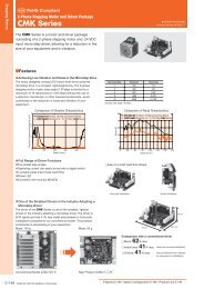
2 Scope of SupplyThanks to the modular hardware components, the frequency inverters can be integratedin the automation concept easily. The scope of delivery described can be supplementedby optional components and adapted to the customer-specific requirements.The plug-in type connection terminals enable a safe function and an economicalassembly.2.1 <strong>Frequency</strong> <strong>Inverter</strong> (0.55 up to 4.0 kW)ACT 201 (230 V) and ACT 401 (400 V)Power range 0.55 kW up to 4.0 kWABCDEFGScope of Supply<strong>Frequency</strong> inverterTerminal strip X1 (Phoenix ZEC 1,5/ST7,5)Plug-in terminals for mains connection and DC linkingTerminal strip X10 (Phoenix ZEC 1.5/3ST5.0)Plug-in terminals for the relay outputStandard fixtures for vertical assemblyBrief <strong>Instruction</strong>s and manuals on CDTerminal strip X2 (Phoenix ZEC 1,5/ST7,5)Plug-in terminal for brake resistor and motor connectionControl terminals X210A / X210B (Wieland DST85 / RM3.5)Plug-in terminal for connection of the control signalsNote:Please check incoming goods for quality, quantity and nature withoutdelay. Obvious defects such as exterior damage of the packing and/orthe unit must be notified to the sender within seven days for insurancereasons.12 02/06
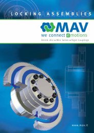
2.2 <strong>Frequency</strong> <strong>Inverter</strong> (5.5 up to 15.0 kW)ACT 401 (400 V)Power range 5.5 kW up to 15.0 kWABCDEScope of Supply<strong>Frequency</strong> inverterTerminal strip X10 (Phoenix ZEC 1.5/3ST5.0)Plug-in terminals for the relay outputStandard fixtures with fixing screws (M4x20, M4x60)for vertical assemblyBrief <strong>Instruction</strong>s and manuals on CDControl terminals X210A / X210B (Wieland DST85 / RM3.5)Plug-in terminal for connection of the control signalsNote:Please check incoming goods for quality, quantity and nature withoutdelay. Obvious defects such as exterior damage of the packing and/or theunit must be notified to the sender within seven days for insurance reasons.02/06 13
2.3 <strong>Frequency</strong> <strong>Inverter</strong> (18.5 up to 30.0 kW)ACT 401 (400 V)Power range 18.5 kW up to 30.0 kWABCDEScope of Supply<strong>Frequency</strong> inverterTerminal strip X10 (Phoenix ZEC 1.5/3ST5.0)Plug-in terminals for the relay outputStandard fixtures with fixing screws (M4x20, M4x70)for vertical assemblyBrief <strong>Instruction</strong>s and manuals on CDControl terminals X210A / X210B (Wieland DST85 / RM3.5)Plug-in terminal for connection of the control signalsNote:Please check incoming goods for quality, quantity and nature withoutdelay. Obvious defects such as exterior damage of the packing and/or theunit must be notified to the sender within seven days for insurance reasons.14 02/06
2.4 <strong>Frequency</strong> <strong>Inverter</strong> (37.0 up to 65.0 kW)ACT 401 (400 V)Power range 37.0 kW up to 65.0 kWABCDEScope of Supply<strong>Frequency</strong> inverterTerminal strip X10 (Phoenix ZEC 1.5/3ST5.0)Plug-in terminals for the relay outputStandard fixtures with fixing screws (M5x20)for vertical assemblyBrief <strong>Instruction</strong>s and manuals on CDControl terminals X210A / X210B (Wieland DST85 / RM3.5)Plug-in terminal for connection of the control signalsNote:Please check incoming goods for quality, quantity and nature withoutdelay. Obvious defects such as exterior damage of the packing and/or theunit must be notified to the sender within seven days for insurance reasons.02/06 15
3 Technical Data3.1 <strong>Frequency</strong> <strong>Inverter</strong> 230 V (0.55 up to 3.0 kW)TypeACT 201 -05 -07 -09 -11 -13 -15Output. motor sideRecommended shaft output P kW 0.55 0.75 1.1 1.5 2.2 3.0 4)Output current I A 3.0 4.0 5.4 5) 7.0 9.54) 5)12.5Long-term overload current (60 s) I A 4.5 6.0 7.3 10.5 14.3 16.2Short-term overload current (1 s) I A 6.0 8.0 8.0 14.0 19.0 19.0Output voltage U V 3 x 0 ... mains voltageDegree of protection - - Short circuit / earth fault proofRotary field frequency f Hz 0 ... 1000, depending on switching frequencySwitching frequency f kHz 2. 4. 8. 12. 16Output brake resistormin. brake resistor (U dBC = 385 V) R Ω 230 160 115 75 55 37Input, mains sideMains current 3) , 3ph/PE3 4 5.5 1) 7 9.5 10.5 1)I A1ph/N/PE ; 2ph/PE5.4 7.2 9.5 2) 13.2 16.5 2) 2) 4)16.5Mains voltage U V 184 ... 264Mains frequency f Hz 45 ... 66Fuse 3ph/PE61016 16I A1ph/N/PE ; 2ph/PE101620 20UL Type 250 VAC RK5, 3ph/PE61015 15I A1ph/N/PE; 2ph/PE101520 20MechanicsDimensions HxWxD mm 190x60x175 250x60x175Weight (approx.) m kg 1.2 1.6Degree of protection - - IP20 (EN60529)Terminals A mm 2 0.2 ... 1.5Form of assembly - - verticalAmbient conditionsEnergy dissipation(2 kHz switching frequency)P W 43 53 73 84 115 170Coolant temperature T n °C 0 ... 40 (3K3 DIN IEC 721-3-3)Storage temperature T L °C -25 ... 55Transport temperature T T °C -25 ... 70Rel. air humidity - % 15 ... 85; not condensingIf required by the customer, the switching frequency may be increased if the output current is reduced at thesame time. Comply with the applicable standards and regulations for this operating point.Output current<strong>Frequency</strong> inverter nominal powerSwitching frequency2 kHz 4 kHz 8 kHz 12 kHz 16 kHz0.55 kW 3.0 A 3.0 A 3.0 A 2.5 A 2.0 A0.75 kW 4.0 A 4.0 A 4.0 A 3.4 A 2.7 A1.1 kW 5.4 A 2) 5.4 A 2) 5) 5.4 A 2) 5) 4.5 A 2) 5) 3.7 A 5)1.5 kW 7.0 A 7.0 A 7.0 A 5.9 A 4.8 A2.2 kW 9.5 A 2) 9.5 A 2) 9.5 A 2) 8.0 A 2) 6.5 A3.0 kW 2) 4) 12.5 A 1) 12.5 A 1) 5) 12.5 A 1) 5) 10.5 A 1) 5) 8.5 A 5)1)Three-phase connection requires a commutating choke.2)One- and two-phase connection requires a commutating choke.3) Mains current with relative mains impedance ≥ 1% (see chapter„Electrical installation“)4) Maximum output current is 9.5 A for one- and two-phase connection.5) Switching frequency is reduced in thermal limit range16 02/06
3.2 <strong>Frequency</strong> <strong>Inverter</strong> 400 V (0.55 up to 4.0 kW)TypeACT 401 -05 -07 -09 -11 -12 -13 -15 -18Output. motor sideRecommended shaft output P kW 0.55 0.75 1.1 1.5 1.85 2.2 3.0 4.0Output current I A 1.8 2.4 3.2 3.8 3) 4.2 5.8 7.8 9.0 3)Long-term overload current (60 s) I A 2.7 3.6 4.8 5.7 6.3 8.7 11.7 13.5Short-term overload current (1 s) I A 3.6 4.8 6.4 7.6 8.4 11.6 15.6 18.0Output voltage U V 3 x 0 ... mains voltageDegree of protection - - Short circuit / earth fault proofRotary filed frequency f Hz 0 ... 1000, depending on switching frequencySwitching frequency f kHz 2. 4. 8. 12. 16Output brake resistormin. brake resistor (U dBC = 770 V) R Ω 930 634 462 300 300 220 148 106Input, mains sideMains current 2) 3ph/PE I A 1.8 2.4 2.8 1) 3.3 1) 4.2 5.8 6.8 1) 7.8 1)Mains voltage U V 320 ... 528Mains frequency f Hz 45 ... 66Fuse 3ph/PE I A 6 10UL-Type 600 VAC RK5. 3ph/PE I A 6 10MechanicsDimensions HxWxD mm 190x60x175 250x60x175Weight (approx.) m kg 1.2 1.6Degree of protection - - IP20 (EN60529)Terminals A mm 2 0.2 ... 1.5Form of assembly - - verticalAmbient conditionsEnergy dissipation(2 kHz Switching frequency)P W 40 46 58 68 68 87 115 130Coolant temperature T n °C 0 ... 40 (3K3 DIN IEC 721-3-3)Storage temperature T L °C -25 ... 55Transport temperature T T °C -25 ... 70Rel. air humidity - % 15 ... 85; not condensingIf required by the customer, the switching frequency may be increased if the output current is reduced at thesame time. Comply with the applicable standards and regulations for this operating point.Output current<strong>Frequency</strong> inverter nominal powerSwitching frequency2 kHz 4 kHz 8 kHz 12 kHz 16 kHz0.55 kW 1.8 A 1.8 A 1.8 A 1.5 A 1.2 A0.75 kW 2.4 A 2.4 A 2.4 A 2.0 A 1.6 A1.1 kW 3.2 A 1) 3.2 A 1) 3.2 A 1) 2.7 A 1) 2.2 A1.5 kW 1) 3.8 A 3.8 A 3) 3.8 A 3) 3.2 A 3) 2.6 A 3)1.85 kW 4.2 A 4.2 A 4.2 A 3.5 A 2.9 A2.2 kW 5.8 A 5.8 A 5.8 A 4.9 A 3.9 A3.0 kW 7.8 A 1) 7.8 A 1) 7.8 A 1) 6.6 A 1) 5.3 A4.0 kW 9.0 A 1) 9.0 A 1) 3) 9.0 A 1) 3) 7.6 A 1) 3) 6.1 A 3)1) Three-phase connection requires a commutating choke.2)Mains current with relative mains impedance ≥ 1% (see chapter„Electrical installation“)3) Switching frequency is reduced in thermal limit range02/06 17
3.3 <strong>Frequency</strong> <strong>Inverter</strong> 400 V (5.5 up to 15.0 kW)TypeACT 401 -19 -21 -22 -23 -25Output. motor sideRecommended shaft output P kW 5.5 7.5 9.2 11.0 15.0Output current I A 14.0 18.0 22.0 3) 25.0 32.0Long-term overload current (60 s) I A 21.0 26.3 30.3 37.5 44.5Short-term overload current (1 s) I A 28.0 33.0 33.0 50.0 64.0Output voltage U V 3 x 0 ... mains voltageDegree of protection - - Short circuit / earth fault proofRotary filed frequency f Hz 0 ... 1000, depending on switching frequencySwitching frequency f kHz 2. 4. 8. 12. 16Output brake resistormin. brake resistor (U dBC = 770 V) R Ω 80 58 48 48 32Input, mains sideMains current 2) 3ph/PE I A 14.2 15.8 1) 20.0 1) 26.0 28.2 1)Mains voltage U V 320 ... 528Mains frequency f Hz 45 ... 66Fuse 3ph/PE I A 16 25 35UL-Type 600 VAC RK5. 3ph/PE I A 20 30 40MechanicsDimensions HxWxD mm 250x100x200 250x125x200Weight (approx.) m kg 3.0 3.7Degree of protection - - IP20 (EN60529)Terminals A mm 2 0.2 ... 6 0.2 ... 16Form of assembly - - verticalAmbient conditionsEnergy dissipation(2 kHz Switching frequency)P W 145 200 225 240 310Coolant temperature T n °C 0 ... 40 (3K3 DIN IEC 721-3-3)Storage temperature T L °C -25 ... 55Transport temperature T T °C -25 ... 70Rel. air humidity - % 15 ... 85; not condensingIf required by the customer, the switching frequency may be increased if the output current is reduced at thesame time. Comply with the applicable standards and regulations for this operating point.Output current<strong>Frequency</strong> inverter nominal powerSwitching frequency2 kHz 4 kHz 8 kHz 12 kHz 16 kHz5.5 kW 14.0 A 14.0 A 14.0 A 11.8 A 9.5 A7.5 kW 18.0 A 1) 18.0 A 1) 18.0 A 1) 15.1 A 1) 12.2 A9.2 kW 1) 23.0 A 22.7 A 3) 22.0 A 3) 18.5 A 3) 15.0 A 3)11 kW 25.0 A 25.0 A 25.0 A 21.0 A 17.0 A15 kW 32.0 A 1) 32.0 A 1) 32.0 A 1) 26.9 A 1) 21.8 A1)Three-phase connection requires a commutating choke.2)Mains current with relative mains impedance ≥ 1% (see chapter„Electrical installation“)3) Switching frequency is reduced in thermal limit range18 02/06
3.4 <strong>Frequency</strong> <strong>Inverter</strong> 400 V (18.5 up to 30.0 kW)TypeACT 401 -27 -29 -31Output. motor sideRecommended shaft output P kW 18.5 22.0 30.0Output current I A 40.0 45.0 60.0Long-term overload current (60 s) I A 60.0 67.5 90.0Short-term overload current (1 s) I A 80.0 90.0 120.0Output voltage U V 3 x 0 ... mains voltageDegree of protection - - Short circuit / earth fault proofRotary filed frequency f Hz 0 ... 1000, depending on switching frequencySwitching frequency f kHz 2. 4. 8Output brake resistormin. brake resistor (U dBC = 770 V) R Ω 16Input, mains sideMains current 2) 3ph/PE I A 42.0 50.0 58.0 1)Mains voltage U V 320 ... 528Mains frequency f Hz 45 ... 66Fuse 3ph/PE I A 50 63UL-Type 600 VAC RK5. 3ph/PE I A 50 60MechanicsDimensions HxWxD mm 250x200x260Weight (approx.) m kg 8Degree of protection - - IP20 (EN60529)Terminals A mm 2 up to 25Form of assembly - - verticalAmbient conditionsEnergy dissipation(2 kHz Switching frequency)P W 445 535 605Coolant temperature T n °C 0 ... 40 (3K3 DIN IEC 721-3-3)Storage temperature T L °C -25 ... 55Transport temperature T T °C -25 ... 70Rel. air humidity - % 15 ... 85; not condensingIf required by the customer, the switching frequency may be increased if the output current is reduced at thesame time. Comply with the applicable standards and regulations for this operating point.Output current<strong>Frequency</strong> inverter nominal powerSwitching frequency2 kHz 4 kHz 8 kHz18.5 kW 40.0 A 40.0 A 40.0 A22 kW 45.0 A 45.0 A 45.0 A30 kW 60.0 A 1) 60.0 A 1) 60.0 A 1)1)Three-phase connection requires a commutating choke.2)Mains current with relative mains impedance ≥ 1% (see chapter„Electrical installation“)02/06 19
3.5 <strong>Frequency</strong> <strong>Inverter</strong> 400 V (37.0 up to 65.0 kW)TypeACT 401 -33 -35 -37 -39Output. motor sideRecommended shaft output P kW 37.0 45.0 55.0 65.0Output current I A 75.0 90.0 110.0 125.0Long-term overload current (60 s) I A 112.5 135.0 165.0 187.5Short-term overload current (1 s) I A 150.0 180.0 220.0 250.0Output voltage U V 3 x 0 ... mains voltageDegree of protection - - Short circuit / earth fault proofRotary filed frequency f Hz 0 ... 1000, depending on switching frequencySwitching frequency f kHz 2. 4. 8Output brake resistormin. brake resistor (U dBC = 770 V) R Ω 7.5Input, mains sideMains current 2) 3ph/PE I A 87.0 104.0 105.0 1) 120.0 1)Mains voltage U V 320 ... 528Mains frequency f Hz 45 ... 66Fuse 3ph/PE I A 100 125 125 125UL-Type 600 VAC RK5. 3ph/PE I A 100 125 125 125MechanicsDimensions HxWxD mm 400x275x260Weight (approx.) m kg 20Degree of protection - - IP20 (EN60529)Terminals A mm 2 up to 70Form of assembly - - VerticalAmbient conditionsEnergy dissipation(2 kHz Switching frequency)P W 665 830 1080 1255Coolant temperature T n °C 0 ... 40 (3K3 DIN IEC 721-3-3)Storage temperature T L °C -25 ... 55Transport temperature T T °C -25 ... 70Rel. air humidity - % 15 ... 85; not condensingIf required by the customer, the switching frequency may be increased if the output current is reduced at thesame time. Comply with the applicable standards and regulations for this operating point.Output current<strong>Frequency</strong> inverter nominal powerSwitching frequency2 kHz 4 kHz 8 kHz37 kW 75.0 A 75.0 A 75.0 A45 kW 90.0 A 90.0 A 90.0 A55 kW 110.0 A 1) 110.0 A 1) 110.0 A 1)65 kW 125.0 A 1) 3) 125.0 A 1) 3) 1) 3)125.0 A1)Three-phase connection requires a commutating choke.2)Mains current with relative mains impedance ≥ 1% (see chapter„Electrical installation“)3) Switching frequency is reduced in thermal limit range20 02/06
3.6 Operation DiagramsThe technical data of the frequency inverters refer to the nominal point which wasselected to enable a wide range of applications. A functionally and efficient dimensioning(de-rating) of the frequency inverters is possible based on the following diagrams.Power reduction (Derating),5%/1000 m above sea level,h = 4000 mOutput current in %max10085604020Site altitudemax. coolant temperature,3.3 °C/1000 m above sea level,Coolant temperature in °C55451000 2000 3000 4000Mounting altitude in m above sea level1000 2000 3000 4000Mounting altitude in m above sea levelCoolant temperaturePower reduction (Derating)2.5%/K upper 40 °C, Tmax= 55 °COutput current in %100806340200 10 20 30 40 50 55Coolant temperature in °CMains voltageReduction of output current at constant output power (Derating)0.22%/ V upper 400 V, Umax=480 VOutput current in %100836340200 400 420 440 460 480Mains voltage equal output voltage in V02/06 21
4 Mechanical InstallationThe frequency inverters of degree of protection IP20 are designed, as a standard, forinstallation in electrical cabinets.• During installation, both the installation and the safety instructions as well as thedevice specifications must be complied with.Warning!To avoid serious physical injuries or major material damage, only qualifiedpersons are allowed to work on the devices.Warning!Caution!During assembly, make sure that no foreign particles (e.g. filings, dust,wires, screws, tools) can get inside the frequency inverter. Otherwisethere is the risk of short circuits and fire.The frequency inverters comply with protection class IP20 only if thecovers and terminals are mounted properly.The units may only be used if these requirements are met.Mount the devices with sufficient clearance to other components so thatthe cooling air can circulate freely. Avoid soiling by grease and air pollutionby dust, aggressive gases, etc.22 02/06
4.1 <strong>Frequency</strong> <strong>Inverter</strong> (0.55 up to 4.0 kW)The frequency inverter is mounted in a vertical position on the assembly panel bymeans of the standard fittings.The following illustration shows the different mounting possibilities.Standard installationxbb1b1cc1aa1a2xx ≥ 100 mmAssembly is effected by inserting the long side of the fixing plate in the heat sink andscrewing it to the mounting plate.The dimensions of the device and the installation dimensions are those of the standarddevice without optional components and are given in millimeters.Dimensions in mmInstallation dimensions in mm<strong>Frequency</strong> inverter a b c a1 a2 b1 c1ACT 2010.55 kW ... 1.1 kW 190 60 175 210 ... 230 255 30 1301.5 kW ... 3.0 kW 250 60 175 270 ... 290 315 30 130ACT 4010.55 kW ... 1.5 kW 190 60 175 210 ... 230 255 30 1301.85 kW ... 4.0 kW 250 60 175 270 ... 290 315 30 130Caution!Mount the devices with sufficient clearance to other components so thatthe cooling air can circulate freely. Avoid soiling by grease and air pollutionby dust, aggressive gases, etc.02/06 23
4.2 <strong>Frequency</strong> <strong>Inverter</strong> (5.5 to 15.0 kW)The frequency inverter is mounted in a vertical position on the assembly panel bymeans of the standard fittings. The following illustration shows the standard fitting.Standard installationxb1bcc1a1aa2xx ≥ 100 mmfixing bracket top(fixing with screws ) M4x20fixing bracket bottom(fixing with screws ) M4x60Assembly is done by screwing the two fixing brackets to the heat sink of the frequencyinverter and the assembly panel.The frequency inverters are provided with fixing brackets, which are fitted using fourthread-cutting screws.The dimensions of the device and the installation dimensions are those of the standarddevice without optional components and are given in millimeters.Dimensions in mmInstallation dimensions in mm<strong>Frequency</strong> inverter a b c a1 a2 b1 c15.5 kW ... 9.2 kW 250 100 200 270 ... 290 315 12 13311.0 kW ... 15.0 kW 250 125 200 270 ... 290 315 17.5 133Caution! Mount the devices with sufficient clearance to other components so thatthe cooling air can circulate freely. Avoid soiling by grease and air pollutionby dust, aggressive gases, etc.24 02/06
4.3 <strong>Frequency</strong> <strong>Inverter</strong> (18.5 up to 30.0 kW)The frequency inverter is mounted in a vertical position on the assembly panel bymeans of the standard fittings. The following illustration shows the standard fitting.Standard installationxb1bcc1a1aa2xx ≥ 100 mmfixing bracket top(fixing with screws M4x20)fixing bracket bottom(fixing with screws M4x70 )Assembly is done by screwing the two fixing brackets to the heat sink of the frequencyinverter and the assembly panel.The frequency inverters are provided with fixing brackets, which are fitted using fourthread-cutting screws. The dimensions of the device and the installation dimensionsare those of the standard device without optional components and are given in millimeters.Dimensions in mmInstallation dimensions in mm<strong>Frequency</strong> inverter a b c a1 a2 b1 c118.5 kW ... 30.0 kW 250 200 290 270 … 290 315 20 165Caution! Mount the devices with sufficient clearance to other components so thatthe cooling air can circulate freely. Avoid soiling by grease and air pollutionby dust, aggressive gases, etc.02/06 25
4.4 <strong>Frequency</strong> inverter (37.0 up to 65.0 kW)The frequency inverter is mounted in a vertical position on the assembly panel bymeans of the standard fittings. The following illustration shows the standard fitting.Standard installationxb1bcc1a1aa2xx ≥ 100 mmfixing braket top(fixing with screws ) M5x20fixing braket bottom(fixing with screws ) M5x20Assembly is done by screwing the two fixing brackets to the heat sink of the frequencyinverter and the assembly panel.The frequency inverters are provided with fixing brackets, which are fitted using fourthread-cutting screws. The dimensions of the device and the installation dimensionsare those of the standard device without optional components and are given in millimeters.Dimensions in mmInstallation dimensions in mm<strong>Frequency</strong> inverter a b c a1 a2 b1 c137.0 kW ... 65.0 kW 400 275 260 425 .. 445 465 20 160Caution! Mount the devices with sufficient clearance to other components so thatthe cooling air can circulate freely. Avoid soiling by grease and air pollutionby dust, aggressive gases, etc.26 02/06
5 Electrical InstallationThe electrical installation must be carried out by qualified staff according to the generaland regional safety and installation directives. For a safe operation of the frequencyinverter it is necessary that the documentation and the device specificationsbe complied with during installation and commissioning. In the case of special applications,you may also have to comply with further guidelines and instructions.Danger!When the frequency inverter is disconnected from power supply, themains, DC-link voltage and motor terminals may still be live for sometime. Wait for some minutes until the DC link capacitors have dischargedbefore starting to work at the unit.The connecting cables must be protected externally, considering the maximum voltageand current values of the fuses. The mains fuses and cable cross-sections are tobe selected according to EN 60204-1 and DIN VDE 0298 Part 4 for the nominal operatingpoint of the frequency inverter. According to UL/CSA, the frequency inverter issuitable for operation at a supply network of a maximum of 480 VAC which delivers amaximum symmetrical current of 5000 A (effective value) if protected by fuses ofclass RK5. Only use copper cables with a temperature range of 60/75 °C.Warning! The frequency inverters are to be grounded properly, i.e. large connectionarea and with good conductivity. The leakage current of the frequencyinverters may be > 3.5 mA. According to EN 50178 a permanentconnection must be provided. The protective conductor cross-sectionrequired for grounding the fixing plate must be at least 10 mm², or asecond protective conductor must be installed electrically parallel to thefirst one. In these applications, the cross-section must correspond to therecommended cross-section of the wire.Connection conditions− The frequency inverter is suited for connection to the public or industrial supplymains according to the technical data. If the transformer output of the supplymains is ≤ 500 kVA, the optional mains commutation choke is only necessary forthe frequency inverters identified in the technical data. The other frequency invertersare suitable for connection without a mains commutating choke with arelative mains impedance ≥ 1%.− It must be checked, based on the specifications of EN 61000-3-2, if the devicescan be connected to the public supply means without taking additional measures.The frequency inverters ≤ 9.2 kW with integrated EMC filter comply with theemission limits of the product standard EN 61800-3 up to a motor cable length of10 m, without additional measures being required. Increased requirements inconnection with the specific application of the frequency inverter are to be met bymeans of optional components. Commutating chokes and EMC filters are optionallyavailable for the series of devices.− Operation on unearthed mains (IT mains) is admissible after disconnection of theY capacitors in the interior of the device.− Interference-free operation with residual-current device is guaranteed at a trippingcurrent ≥ 30 mA if the following points are observed:− Pulse-current and alternating-current sensitive residual current devices (TypeA to EN 50178) in the case of a connection of frequency inverters with onephasepower supply (L1/N)1. All-current sensitive residual current devices (Type B to EN 50178) in the caseof a connection of frequency inverters with two-phase (L1/L2) or three-phase(L1/L2/L3) power supply.2. Use EMC filters with reduced leakage current or, if possible, do not use EMCfilters at all.3. The length of the shielded motor cable is ≤ 10 m and there are no additionalcapacitive components between the mains or motor cables and PE.02/06 27
5.1 EMC InformationThe frequency inverters are designed according to the requirements and limit valuesof product norm EN 61800-3 with an interference immunity factor (EMI) for operationin industrial applications. Electromagnetic interference is to be avoided by expertinstallation and observation of the specific product information.Measures• Install the frequency inverters and commutating chokes on a metal mountingpanel. Ideally, the mounting panel should be galvanized.• Provide proper equipotential bonding within the system or the plant. Plant componentssuch as control cabinets, control panels, machine frames, etc. must beconnected by means of PE cables.• Connect the frequency inverter, the commutating choke, external filters and othercomponents to an earthing point via short cables.• Keep the cables as short as possible, make sure that cables are installed properlyusing appropriate cable clamps, etc.• Contactors, relays and solenoids in the electrical cabinet are to be provided withsuitable interference suppression components.CAttention!ABA Mains ConnectionThe length of the mains supply cable is not limited.However, it must be installed separate fromthe control, data and motor cables.B DC link connectionThe frequency inverters are to be connected tothe same mains potential or a common directvoltage source. Cables longer than 300 mm are tobe shielded. The shield must be connected to themounting panel on both sides.C Control ConnectionThe control and signal cables must be kept physicallyseparate from the power cables. The shieldof the control cables is to be connected to groundpotential properly, i.e. with good conductivity, onboth sides. Analog signal lines are to be connectedto the shield potential on one side.DD Motor and brake resistorThe shield of the motor cable is to be connectedto ground potential properly on both sides. On themotor side use a metal compression gland. On thefrequency inverter side an appropriate shieldclamp is to be used. The signal cable used formonitoring the motor temperature must be keptseparate from the motor cable. Connect the shieldof this line on both sides. If a brake resistor isused, the connection cable must also be shielded,and the shield is to be connected to earth potentialon both sides.The frequency inverters meet the requirements of the low-voltage directive73/23/EEC and the requirements of the EMC directive 89/336/EEC.The EMC product standard EN 61800-3 relates to the drive system. Thedocumentation provides information on how the applicable standardscan be complied if the frequency inverter is a component of the drivesystem. The declaration of conformity is to be issued by the supplier ofthe drive system.28 02/06
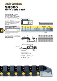
5.2 Block diagramX10A 1S3OUT23X210A1 +20 V / 180 mA2 GND 20 VB 3S1INDC 4 S2IND5 S3INDS4IND67 S5INDCPUU, IX1 L1 L2 L3+ -+ -X210B1 S6INDDE2 GND 20 VS1OUT34 MFO1F567+10 V / 4 mAMFI1 ADGND 10 VIX2 UV WRb1 Rb2A Relay connection S3OUTChange-over contact, response time approx. 40 ms, maximum contact load:− make contact 5 A / 240 V AC, 5 A (ohmic) / 24 V DC− break contact 3 A / 240 V AC, 1 A (ohmic) / 24 V DCB Digital input S1INDDigital signal, controller enable signal, response time approx. 16 ms (on), 10 μs (off),U max = 30 V, 10 mA at 24 V, PLC compatibleC Digital input S2IND ... S6INDDigital signal: response time approx. 16 ms, U max = 30 V, 10 mA at 24 V, PLC compatible,frequency signal: 0...30 V, 10 mA at 24 V, f max = 150 kHzD Digital output S1OUTDigital signal, 24 V, I max = 40 mA,PLC compatible, overload and short-circuit proofE Multi-function output MFO1analog signal: 24 V, I max = 40 mA, pulse-width modulated, f PWM = 116 HzDigital signal: 24 V, I max = 40 mA,frequency signal: 0...24 V, I max = 40 mA, f max = 150 kHz,PLC compatible, overload and short-circuit proofF Multi-function input MFI1analog signal: resolution 12 Bit, 0...10 V (Ri = 70 kΩ), 0...20 mA (Ri = 500 Ω),digital signal: response time approx. 16 ms, U max = 30 V, 4 mA at 24 V,PLC compatible02/06 29
5.3 Mains ConnectionThe mains fuses and cable cross-sections are to be selected according to EN 60204-1and DIN VDE 0298 Part 4 for the nominal operating point of the frequency inverter.According to UL/CSA, approved Class 1 copper lines with a temperature range of60/75°C and matching mains fuses are to be used for the power cables. The electricalinstallation is to be done according to the device specifications and the applicablestandards and directives.Caution! The control, mains and motor lines must be kept physically separatefrom one another. The cables connected to the frequency inverters maynot be subjected to high-voltage insulation tests unless appropriate circuitrymeasures are taken before. Otherwise the unit may be damaged.5.3.1 <strong>Frequency</strong> <strong>Inverter</strong> (0.55 up to 4.0 kW)The mains connection of the frequency inverter is via plug-in terminal X1. Degree ofprotection IP20 (EN60529) is only guaranteed if terminal X1 is plugged in.Danger! Switch off power supply before connecting or disconnecting thekeyed plug-in terminal X1. Dangerous voltage may be present at themains terminals and the DC terminals even after the frequency inverterhas been disconnected safely from power supply. Wait for some minutesuntil the DC link capacitors have discharged before starting the work.• The unit may only be connected with the power supply switched off.• Make sure that the frequency inverter is discharged.Mains power connection 0.55 kW up to 4.0 kWX1 Phoenix ZEC 1,5/ .. ST7,520.2 … 1.5 mmAWG 24 … 1620.2 … 1.5 mmAWG 24 … 1620.25 … 1.5 mmAWG 22 … 1620.25 … 1.5 mmAWG 22 … 16550 W … 1.1 kWL1 L2 L3+ -+ -L1 L2 L3+ -L1 L2 L3L1 N PE1ph / <strong>230V</strong> AC1.5 kW … 3.0 kWL1+ - L1 L2 L3L1 L2 PE2ph / <strong>230V</strong> ACL1 L2 L3 PE3ph / <strong>230V</strong> AC3ph / <strong>400V</strong> AC1.5 kW … 3.0 kW 1.5 kW … 4.0 kWL1L1+ - L1 L2 L3+ - L1 L2 L3L1 N PEL1 L2 PE L1 L2 L3 PE1ph / <strong>230V</strong> AC2ph / <strong>230V</strong> AC3ph / <strong>230V</strong> AC3ph / <strong>400V</strong> AC1 With a mains current above 10 A, the mains power connection 230 V 1ph/N/PEand the mains power connection 230 V 2ph/N/PE are to be done on two terminals.30 02/06
5.3.2 <strong>Frequency</strong> <strong>Inverter</strong> (5.5 up to 15.0 kW)Danger!Switch off power supply before connecting or disconnecting themains cable to terminal X1. Dangerous voltage may be present at themains terminals and the DC terminals even after the frequency inverterhas been disconnected safely from power supply. Wait for some minutesuntil the DC link capacitors have discharged before starting the work.• The unit may only be connected with the power supply switched off.• Make sure that the frequency inverter is discharged.Mains power connection 5.5 kW up to 15.0 kWX1X1L1 L2 L3-+L1 L2 L3 PE3ph / <strong>400V</strong> AC5.5 kW … 9.2 kWWAGO Serie 745 / 6qmm / RM7,520.2 … 6 mmAWG 24 … 1020.2 … 6 mmAWG 24 … 1020.25 … 4 mmAWG 22 … 1220.25 … 4 mmAWG 22 … 1611 kW … 15 kWWAGO Serie 745 / 16qmm / RM10+1520.2 … 16 mmAWG 24 … 620.2 … 16 mmAWG 24 … 620.25 … 10 mmAWG 22 … 820.25 … 10 mmAWG 22 … 802/06 31
5.3.3 <strong>Frequency</strong> <strong>Inverter</strong> (18.5 up to 30.0 kW)Danger!Switch off power supply before connecting or disconnecting themains cable to terminal X1. Dangerous voltage may be present at themains terminals and the DC terminals even after the frequency inverterhas been disconnected safely from power supply. Wait for some minutesuntil the DC link capacitors have discharged before starting the work.• The unit may only be connected with the power supply switched off.• Make sure that the frequency inverter is discharged.Mains power connection 18.5 kW up to 30.0 kWX1X1L1 L2 L3- +L1 L2 L3 PE3ph / <strong>400V</strong> AC2.5 Nm22.1 lb-in18.5 kW … 30.0 kWPHOENIX MKDSP 25/ 6-15,00-F20.5 … 35 mmAWG 20 … 220.5 … 25 mmAWG 20 … 421.00 … 25 mmAWG 18 … 421.5 … 25 mmAWG 16 … 432 02/06
5.3.4 <strong>Frequency</strong> <strong>Inverter</strong> (37.0 up to 65.0 kW)Danger!Switch off power supply before connecting or disconnecting themains cable to terminal X1. Dangerous voltage may be present at themains terminals and the DC terminals even after the frequency inverterhas been disconnected safely from power supply. Wait for some minutesuntil the DC link capacitors have discharged before starting the work.• The unit may only be connected with the power supply switched off.• Make sure that the frequency inverter is discharged.Mains power connection 37.0 kW up to 65.0 kWX1X1L1 L2 L3-+8 Nm70.8 lb-in37.0 kW … 65.0 kWthreaded bolt M8x252wire cross section up to 70 mmL1 L2 L3 PE3ph / <strong>400V</strong> AC02/06 33
5.4 Motor ConnectionThe connection of the motor and the brake resistor to the frequency inverter is to bedone using shielded cables. The shield is to be connected to PE potential properly, i.e.with good conductivity, on both sides. The control, mains and motor lines must bekept physically separate from one another. The user must comply with the applicablelimits stipulated in the relevant national and international directives as regards theapplication, the length of the motor cable and the switching frequency.Permissible length of motor cable without output filter<strong>Frequency</strong> inverter unshielded cable shielded cable0.55 kW … 1.5 kW 50 m 25 m1.85 kW … 4.0 kW 100 m 50 m5.5 kW … 9.2 kW 100 m 50 m11.0 kW … 15.0 kW 100 m 50 m18.5 kW … 30.0 kW 150 m 100 m37.0 kW … 65.0 kW 150 m 100 mThe specified lengths of the motor cables must not be exceeded if no output filter isinstalled.Upon request, we will check if longer motor cables can be used after taking appropriatetechnical measures, e.g. use of low-capacitance cables and output filters. Thefollowing table includes standard values if an output filter is usedPermissible length of motor cable with output filter<strong>Frequency</strong> inverter unshielded cable shielded cable0.55 kW … 1.5 kW on inquiry on inquiry1.85 kW … 4.0 kW 150 m 100 m5.5 kW … 9.2 kW 200 m 135 m11.0 kW … 15.0 kW 225 m 150 m18.5 kW … 30.0 kW 300 m 200 m37.0 kW … 65.0 kW 300 m 200 mNote:The frequency inverters ≤ 9.2 kW with integrated EMC filter comply withthe emission limits stipulated in EN 61800-3 if the motor cable is notlonger than 10 m. Customer-specific requirements can be met by meansof an optional filter.34 02/06
5.4.1 <strong>Frequency</strong> <strong>Inverter</strong> (0.55 up to 4.0 kW)The connection of the motor and the brake resistor to the frequency inverter is to bedone via plug-in terminal X2. Degree of protection IP20 (EN60529) is only guaranteedif terminal X2 is connected.Danger!Switch off power supply before connecting or disconnecting thekeyed plug-in terminal X2. Dangerous voltage may be present at themotor terminals and the terminals of the brake resistor even after thefrequency inverter has been disconnected safely from power supply.Wait for some minutes until the DC link capacitors have discharged beforestarting to work at the unit.• The unit may only be connected with the power supply switched off.• Make sure that the frequency inverter is discharged.Motor power connection 0.55 kW up to 4.0 kWPhoenix ZEC 1,5/ .. ST7,520.2 … 1.5 mmAWG 24 … 16X220.2 … 1.5 mmAWG 24 … 1620.25 … 1.5 mmAWG 22 … 1620.25 … 1.5 mmAWG 22 … 16Rb1 Rb2UVWUV WUV WDelta connectionStar connectionM3~02/06 35
5.4.2 <strong>Frequency</strong> <strong>Inverter</strong> (5.5 up to 15.0 kW)The connection of the motor to the frequency inverter is to be done via terminal X2.Danger!Switch off power supply before connecting or disconnecting the motorcables to terminal X2. Dangerous voltage may be present at themotor terminals and the terminals of the brake resistor even after thefrequency inverter has been disconnected safely from power supply.Wait for some minutes until the DC link capacitors have discharged beforestarting to work at the unit.• The unit may only be connected with the power supply switched off.• Make sure that the frequency inverter is discharged.Motor power connection 5.5 kW up to 15.0 kWX2UVWRb1 Rb2X2UV WUV WM3~Delta connectionStar connection5.5 kW … 9.2 kWWAGO Serie 745 / 6qmm / RM7,520.2 … 6 mmAWG 24 … 1020.2 … 6 mmAWG 24 … 1020.25 … 4 mmAWG 22 … 1220.25 … 4 mmAWG 22 … 1611.0 kW … 15.0 kWWAGO Serie 745 / 16qmm / RM10+1520.2 … 16 mmAWG 24 … 620.2 … 16 mmAWG 24 … 620.25 … 10 mmAWG 22 … 820.25 … 10 mmAWG 22 … 836 02/06
5.4.3 <strong>Frequency</strong> <strong>Inverter</strong> (18.5 up to 30.0 kW)The connection of the motor to the frequency inverter is to be done via terminal X2.Danger!Switch off power supply before connecting or disconnecting the motorcables to terminal X2. Dangerous voltage may be present at themotor terminals and the terminals of the brake resistor even after thefrequency inverter has been disconnected safely from power supply.Wait for some minutes until the DC link capacitors have discharged beforestarting to work at the unit.• The unit may only be connected with the power supply switched off.• Make sure that the frequency inverter is discharged.Motor power connection 18.5 kW up to 30.0 kWX2UVWRb1 Rb218.5 kW … 30 kWPHOENIX MKDSP 25/ 6-15,00-F20.5 … 35 mmAWG 20 … 220.5 … 25 mmAWG 20 … 421.00 … 25 mmAWG 18 … 421.5 … 25 mmAWG 16 … 4X22.5 Nm22.1 lb-inU V WStar connectionM3~U VWDelta connection02/06 37
5.4.4 <strong>Frequency</strong> <strong>Inverter</strong> (37.0 up to 65.0 kW)The connection of the motor to the frequency inverter is to be done via terminal X2.Danger!Switch off power supply before connecting or disconnecting the motorcables to terminal X2. Dangerous voltage may be present at themotor terminals and the terminals of the brake resistor even after thefrequency inverter has been disconnected safely from power supply.Wait for some minutes until the DC link capacitors have discharged beforestarting to work at the unit.• The unit may only be connected with the power supply switched off.• Make sure that the frequency inverter is discharged.Motor power connection 37.0 kW up to 65.0 kWX2X237.0 kW … 65.0 kWthreaded bolt M8x25UVWRb1 Rb2wire cross section up to 70 mm 28 Nm70.8 lb-inUVWUV WM3~Star connection Delta connection38 02/06
5.5 Connection of a Brake ResistorConnection of a brake resistor is done via terminal X2.Danger!Switch off power supply before connecting or disconnecting the brakeresistor cables to terminal X2. Dangerous voltage may be present at themotor terminals and the terminals of the brake resistor even after thefrequency inverter has been disconnected safely from power supply. Waitfor some minutes until the DC link capacitors have discharged beforestarting to work at the unit.• The unit may only be connected with the power supply switched off.• Make sure that the frequency inverter is discharged.Caution!The brake resistor must be equipped with a temperature switch. The temperatureswitch must disconnect the frequency inverter from mains supplyif the brake resistor is overloaded.5.5.1 <strong>Frequency</strong> <strong>Inverter</strong> (0.55 up to 4.0 kW)Degree of protection IP20 (EN60529) is only guaranteed if terminal X2 is connected.Connection of brake resistor with temperature switchX2X2Rb1 Rb2 UVWPhoenix ZEC 1,5/ .. ST7,520.2 … 1.5 mmAWG 24 … 1620.2 … 1.5 mmAWG 24 … 16Rb1T1R bRb2T220.25 … 1.5 mmAWG 22 … 1620.25 … 1.5 mmAWG 22 … 1602/06 39
5.5.2 <strong>Frequency</strong> <strong>Inverter</strong> (5.5 up to 15.0 kW)Connection of brake resistor with temperature switchX2UVWRb1 Rb2X25.5 kW … 9.2 kWWAGO Serie 745 / 6qmm / RM7,520.2 … 6 mmAWG 24 … 1020.2 … 6 mmAWG 24 … 1020.25 … 4 mmAWG 22 … 1220.25 … 4 mmAWG 22 … 16Rb1T1R bRb2T211.0 kW … 15.0 kWWAGO Serie 745 / 16qmm / RM10+1520.2 … 16 mmAWG 24 … 620.2 … 16 mmAWG 24 … 620.25 … 10 mmAWG 22 … 820.25 … 10 mmAWG 22 … 85.5.3 <strong>Frequency</strong> <strong>Inverter</strong> (18.5 up to 30.0 kW)Connection of brake resistor with temperature switchX2UVWRb1 Rb2X2Rb1R bRb218.5 kW … 30 kWPHOENIX MKDSP 25/ 6-15,00-F20.5 … 35 mmAWG 20 … 220.5 … 25 mmAWG 20 … 421.00 … 25 mmAWG 18 … 421.5 … 25 mmAWG 16 … 42.5 Nm22.1 lb-inT1T240 02/06
5.5.4 <strong>Frequency</strong> <strong>Inverter</strong> (37.0 up to 65.0 kW)Connection of brake resistor with temperature switchX2UVWRb1 Rb2X237.0 kW … 65.0 kWthreaded bolt M8x25Wire cross section up to 70 mm 28 Nm70.8 lb-inRb1T1R bRb2T202/06 41
5.6 Control TerminalsThe control and software functionality can be freely configured to ensure a reliableand economical operation. The operating instructions describe the factory settings ofthe standard connections in the relevant Configuration 30 as well as the softwareparameters to be set up.Caution!Switch off power supply before connecting or disconnecting the keyedcontrol inputs and outputs. Otherwise, components may be damaged.• The unit may only be connected with the power supply switched off.• Make sure that the frequency inverter is discharged.Control TerminalsWieland DST85 / RM3,520.14 … 1.5 mmAWG 30 … 1620.14 … 1.5 mmAWG 30 … 1620.25 … 1.0 mmAWG 22 … 1820.25 … 0.75 mmAWG 22 … 200.2 … 0.3 Nm1.8 … 2.7 lb-inControl terminal X210ATer.Description1 Voltage output 20 V, I max =180 mA 1)2 Ground / GND 20 V3 Digital input S1IND, U max =30 V, 10 mA at 24 V, PLC compatible,response time approx. 16ms (on), 10 μs (off)4 Digital input EM-S2IND, U max =30 V, 10 mA at 24 V, PLC compatible,response time approx. 16 ms5 Digital input EM-S3IND, U max =30 V, 10 mA at 24 V, PLC compatible,response time approx. 16 ms6 Digital input S4IND, U max = 30 V, 10 mA at 24 V, PLC compatible,frequency signal: 0...30 V, 10 mA at 24 V, f max = 150 kHz7 Digital input S5IND, U max = 30 V, 10 mA at 24 V, PLC compatible,frequency signal: 0...30 V, 10 mA at 24 V, f max = 150 kHzControl terminal X210BTer.Description1 Digital input S6IND, U max =30 V, 10 mA at 24 V, PLC compatible,response time approx. 16 ms2 Ground / GND 20 V3 Digital output S1OUT, U=24 V, I max =40 mA, overload and short-circuit proof4 Multi-function output MFO1,analog signal: U=24 V, I max =40 mA, pulse-width modulated, f PWM =116 Hzdigital signal: U=24 V, I max =40 mA, overload and short-circuit proof,frequency signal: 0...24 V, I max =40 mA, f max =150 kHz5 Reference output 10 V, I max =4 mA6 Multi-function input MFI1,analog signal: resolution 12 Bit, 0...+10 V (Ri = 70 kΩ), 0...20 mA (Ri = 500 Ω),digital signal: response time approx. 16 ms, U max = 30 V, 4 mA at 24 V,PLC compatible7 Ground / GND 10 V1) The power supply at terminal X210A.1 may be loaded with a maximum current of I max =180 mA. The maximum current available is reduced by the digital output S1OUT and multifunctionaloutput MFO1.42 02/06
5.6.1 Relay OutputBy default, the freely programmable relay output is linked to the monitoring function(factory setting). The logic link to various functions can be freely configured via thesoftware parameters. Connection of the relay output is not absolutely necessary forthe function of the frequency inverter.Relay OutputX10Phoenix ZEC 1,5/3ST5,020.2 … 1.5 mmX10AWG 24 … 16210.2 … 1.5 mm2 S3OUTAWG 24 … 16230.25 … 1.5 mmAWG 22 … 1620.25 … 1.5 mmAWG 22 … 16Control terminal X10Ter.Description1 .. 3 Relay output, floating change-over contact, response time approx. 40 ms,max. contact load, make contact 5 A / 240 V AC, 5 A (ohmic) / 24 V DCmax. contact load, break contact 3 A / 240 V AC, 1 A (ohmic) / 24 V DC02/06 43
5.6.2 Control Terminals – Terminal DiagramThe control hardware and the software of the frequency inverter are freely configurableto a great extent. Certain functions can be assigned to the control terminals, andthe internal logic of the software modules can be freely selected.Thanks to the modular design, the frequency inverter can be adapted to a greatrange of different driving tasks.The demands made of the control hardware and software are well known in the caseof standard driving tasks. This control terminal logic and internal function assignmentsof the software modules are available in standard configurations. These assignmentscan be selected via parameter Configuration 30. For information on otherconfigurations, please contact us.5.6.2.1 Configuration 110 – Sensorless ControlConfiguration 110 contains the functions for variable-speed control of a 3-phase machinein a wide range of standard applications. The motor speed is set according tothe selected ratio of the reference frequency to the necessary voltage.M-+-V+X210A1 +20 V/180 mA2 GND 20 V3 S1IND4 S2IND5 S3IND6 S4IND7 S5INDX210BS6IND1234567GND 20 VS1OUTMFO1A+10 V/ 4 mAMFI1AGND 10 VControl terminal X210AX210A.1 Supply voltage +20VX210A.2 Ground 20 VX210A.3 Controller release / error acknowledgmentX210A.4 Start of clockwise operationX210A.5 Start of anticlockwise operationX210A.6 Data set change-over 1X210A.7 Data set change-over 2Control terminal X210BX210B.1 Motor thermal contactX210B.2 Ground 20 VX210B.3 <strong>Operating</strong> messageX210B.4 Analog signal of actual frequencyX210B.5 Supply voltage +10VReference value potentiometerX210B.6 Reference speed 0 ...+10 VX210B.7 Ground 10 V44 02/06
5.6.2.2 Configuration 111 – Sensorless Controlwith Technology ControllerConfiguration 111 extends the functionality of the sensorless control by software functionsfor easier adaptation to the customer's requirements in different applications.The Technology Controller enables flow rate, pressure, level or speed control.M-+-V++-X210A1 +20 V/180 mA2 GND 20 V3 S1IND4 S2IND5 S3IND6 S4IND7 S5INDX210BS6IND1234567GND 20 VS1OUTMFO1A+10 V/4 mAMFI1AGND 10 VControl terminal X210AX210A.1 Supply voltage +20VX210A.2 Ground 20 VX210A.3 Controller release / error acknowledgmentX210A.4 Fixed percentage valuechange-over 1X210A.5 Fixed percentage valuechange-over 2X210A.6 Data set change-over 1X210A.7 Data set change-over 2Control terminal X210BX210B.1 Motor thermal contactX210B.2 Ground 20 VX210B.3 <strong>Operating</strong> messageX210B.4 Analog signal of actual frequencyX210B.5 Supply voltage +10VX210B.6 Actual percentage value 0 ...+10 VX210B.7 Ground 10 V5.6.2.3 Configuration 410 – Sensorless Field-Oriented ControlConfiguration 410 contains the functions for sensorless, field-oriented control of a 3-phase machine. The current motor speed is determined from the present currents andvoltages in combination with the machine parameters. Separate control of torque andflux-forming current enables a high drive dynamism at a high load moment.M-+-V+X210A1 +20 V/180 mA2 GND 20 V3 S1IND4 S2IND5 S3IND6 S4IND7 S5INDX210BS6IND1234567GND 20 VS1OUTMFO1A+10 V/4 mAMFI1AGND 10 VControl terminal X210AX210A.1 Supply voltage +20VX210A.2 Ground 20 VX210A.3 Controller release / error acknowledgmentX210A.4 Start of clockwise operationX210A.5 Start of anticlockwise operationX210A.6 Data set change-over 1X210A.7 Data set change-over 2Control terminal X210BX210B.1 Motor thermal contactX210B.2 Ground 20 VX210B.3 <strong>Operating</strong> messageX210B.4 Analog signal of actual frequencyX210B.5 Supply voltage +10VReference value potentiometerX210B.6 Reference speed 0 ...+10 VX210B.7 Ground 10 V02/06 45
5.6.2.4 Configuration 411 – Sensorless Field-Oriented Controlwith Technology ControllerConfiguration 411 extends the functionality of the sensor-less field-oriented control ofConfiguration 410 by a Technology Controller. The Technology Controller enables acontrol based on parameters such as flow rate, pressure, filling level or speed.M-+-V++-X210A1 +20 V/180 mA2 GND 20 V3 S1IND4 S2IND5 S3IND6 S4IND7 S5INDX210BS6IND1234567GND 20 VS1OUTMFO1A+10 V/4 mAMFI1AGND 10 VControl terminal X210AX210A.1 Supply voltage +20VX210A.2 Ground 20 VX210A.3 Controller release / error acknowledgmentX210A.4 Fixed percentage valuechange-over 1X210A.5 no function assignedX210A.6 Data set change-over 1X210A.7 Data set change-over 2Control terminal X210BX210B.1 Motor thermal contactX210B.2 Ground 20 VX210B.3 <strong>Operating</strong> messageX210B.4 Analog signal of actual frequencyX210B.5 Supply voltage +10VX210B.6 Actual percentage value 0 ...+10 VX210B.7 Ground 10 V5.6.2.5 Configuration 430 – Sensorless Field-Oriented Control,speed or torque controlledConfiguration 430 extends the functionality of the sensor-less field-oriented control ofConfiguration 410 by a Torque Controller. The reference torque is represented as apercentage and it is transmitted into the corresponding operational performance ofthe application. Change-over between variable-speed control and torque-dependentcontrol is done via a digital control input.M-+-V+X210A1 +20 V/180 mA2 GND 20 V3 S1IND4 S2IND5 S3IND6 S4IND7 S5INDX210BS6IND1234567GND 20 VS1OUTMFO1A+10 V/4 mAMFI1AGND 10 VControl terminal X210AX210A.1 Supply voltage +20VX210A.2 Ground 20 VX210A.3 Controller release / error acknowledgmentX210A.4 Start of clockwise operationX210A.5 n-/T change-over control functionX210A.6 Data set change-over 1X210A.7 Data set change-over 2Control terminal X210BX210B.1 Motor thermal contactX210B.2 Ground 20 VX210B.3 <strong>Operating</strong> messageX210B.4 Analog signal of actual frequencyX210B.5 Supply voltage +10 VReference value potentiometerX210B.6 Reference speed 0 ...+10 VX210B.7 Ground 10 V46 02/06
5.6.2.6 Configuration 210 – Field-Oriented Control,speed controlledConfiguration 210 contains the functions for speed-controlled, field-oriented control ofa 3-phase machine with speed sensor feedback. The separate control of torque andflux-forming current enables high drive dynamism with a high load moment. The necessaryspeed sensor feedback results in a precise speed and torque performance.+ -M-+-V+X210A1 +20 V/180 mA2 GND 20 V3 S1IND4 S2IND5 S3INDB6 S4INDA7 S5INDX210BS6IND1234567GND 20 VS1OUTMFO1A+10 V/4 mAMFI1AGND 10 VControl terminal X210AX210A.1 Supply voltage +20VX210A.2 Ground 20 VX210A.3 Controller release / error acknowledgmentX210A.4 Start of clockwise operationX210A.5 Start of anticlockwise operationX210A.6 Speed sensor track BX210A.7 Speed sensor track AControl terminal X210BX210B.1 Motor thermal contactX210B.2 Ground 20 VX210B.3 <strong>Operating</strong> messageX210B.4 Analog signal of actual frequencyX210B.5 Supply voltage +10 VReference value potentiometerX210B.6 Reference speed 0 ...+10VX210B.7 Ground 10 V5.6.2.7 Configuration 230 – Field-Oriented Control,speed and torque controlledConfiguration 230 extends the functionality of Configuration 210 by functions fortorque-dependent, field-oriented control. The reference torque is represented as apercentage and it is transmitted into the corresponding operational performance ofthe application. Change-over between variable-speed control and torque-dependentcontrol is done via a digital control input.+ -M-+-V+X210A1 +20 V/180 mA2 GND 20 V3 S1IND4 S2IND5 S3INDB6 S4INDA7 S5INDX210BS6IND1234567GND 20 VS1OUTMFO1A+10 V/4 mAMFI1AGND 10 VControl terminal X210AX210A.1 Supply voltage +20VX210A.2 Ground 20 VX210A.3 Controller release / error acknowledgmentX210A.4 Start of clockwise operationX210A.5 n-/T change-over control functionX210A.6 Speed sensor track BX210A.7 Speed sensor track AControl terminal X210BX210B.1 Motor thermal contactX210B.2 Ground 20 VX210B.3 <strong>Operating</strong> messageX210B.4 Analog signal of actual frequencyX210B.5 Supply voltage +10 VReference value potentiometerX210B.6 Reference speed 0 ...+10VX210B.7 Ground 10 V02/06 47
5.7 Optional ComponentsThanks to the modular hardware components, the frequency inverters can be integratedin the automation concept easily. The standard and optional modules are recognizedduring the initialization, and the controller functionality is adjusted automatically.For the information required for installation and handling of the optional modules,refer to the corresponding documentation.Danger!The hardware modules at slots B and C may only be assembled and disassembledafter the frequency inverter has been disconnected safely frompower supply. Wait for some minutes until the DC link capacitors havedischarged before starting the work.• The unit may only be connected with the power supply switched off.• Make sure that the frequency inverter is discharged.Hardware modulesA Control Unit KP500Connection of the optional control unit KP500 or an interfaceadapter KP232.BCAB Communication module CMPlug-in section for connection to various communication protocols:− CM-232: RS232 interface1 CM-485: RS485 interface2 CM-PDP: Profibus-DP interface3 CM-CAN: CANopen interfaceC Expansion module EMSlot for customer-specific adaptation of the control inputsand outputs to various applications:4 EM-ENC: extended speed sensor evaluation5 EM-RES: resolver evaluation6 EM-IO: analog and digital inputs and outputs7 EM-SYS: system-bus(system bus in combination with CM-CAN communicationmodule upon request)Attention!If two optional components with CAN-Protocol controller are installed,the system-bus interface in the EM expansion module is deactivated!48 02/06
6 Control Unit KP500The optional KP500 control unit is a practical tool for controlling the frequency inverterand setting and displaying the frequency inverter parameters.The control unit is not absolutely necessary for the operation of the frequency inverterand can be plugged on when required.ABFCDGEHIJKeysA RUN Used for starting the drive and opening the CTRL menu.Press the RUN key to open the motor potentiometer function.STOP Used for opening the CTRL menu, stopping the drive and acknowledgingfaultsJ ▲ ▼ Used for navigating in the menu structure and selecting parameters.Used for increasing/decreasing parameter values.ENT Used for opening parameters or switching to another menu within the menustructure. Confirmation of the selected function or the set parameter.ESC Used for aborting parameters or switching back to the previous menu withinthe menu structure. Canceling the function or resetting the parameter value.FUN Used for switching over the key function, access to special functions.DisplayB Three-digit 7-segment display to show the parameter numberC One-digit 7-segment display for display of the active data record, direction of rotationetc.D Display of the selected menu branch:VAL Display actual valuesPARA Select parameters and adjust parameter values.CTRL Select a function for adjustment and/or display via the control unit:SEtUP guided commissioningCtrL motor potentiometer and jog functionCPY Copy parameters via the control unit:ALL All the parameter values are copied.Act Only the active parameter values are copied.FOr Control unit memory is formatted and deleted.E Status and operating messages:WARN Warning about a critical operating behaviorFAULT Message indicating that the unit was switched off due to a faultRUN Flashing: signals readiness for operationLights up: signals that the unit is operating and the output stage is enabledREM Active remote control via interface connectionF Function switch-over with the FUN keyF Five-digit 7-segment display for display of parameter value and signG Physical unit of the parameter value displayedH Active acceleration or deceleration rampI Current direction of rotation of the drive02/06 49
6.4 Parameter Menu (PARA)The parameters to be configured during the guided commissioning were selected fromcommon applications and can be supplemented as required by further settings in thePARA menu branch. The parameters and basic software functions linked to the correspondingactual value are documented in the operating instructions.ESCEAENTBCENTESCDAUse the arrow keys to select the required number from the parameters displayedin numerical order. The parameter number is displayed with the active data set(flashes).In the current data set, the related parameters are displayed, including the correspondingdata set number. The seven-segment display shows data set 0 if theparameter values in the four data sets are identical.▲ + ▼FUN , ▲FUN , ▼KeysChange to the last parameter edited.Display of last parameter (highest number).Display of first parameter (lowest number).BCUse the ENT key to select the parameter. The parameter is displayed includingits value, unit and the active data set. If settings are edited in data set 0, theparameter values are changed in the four data sets.Use the arrow keys to adjust the parameter value or to select an operationmode. The adjustment possibilities you have depend on the parameter.Keep the arrow keys pressed for a while to change the displayed values quickly.If you release the keys again, the speed at which the values change is reducedagain.If the parameter value starts to flash, the speed at which the values change isreset to the initial value again.▲ + ▼FUN , ▲FUN , ▼FUN , ENTKeysSet parameter to factory setting.Set parameter to highest value.Set parameter to smallest value.Change of the data set in the case of data set related parameters.DUse the ENT key to save the parameter. For a short time, the message SEt includingthe parameter number and the data set is displayed. To leave the parameterunchanged, press the ESC key.Err1: EEPrOErr2: StOPErr3: ErrorMessagesParameter has not been saved.Parameter can only be read (i.e. not edited) when the unit is inoperation.Other errorEAfter saving the parameter, you can edit the value again or return to the parameterselection menu by pressing the ESC key.52 02/06
6.5 Copy Menu (CPY)With the copy function of the control unit you can copy the parameter values from thefrequency inverter to a non-volatile memory of the control unit (upload) and store(download) them to a frequency inverter again.The copy function makes the parameterization of recurring applications much easier.The function archives all parameter values, regardless of access control and valuerange. The memory space available in the control unit for the files is dynamicallyscaled to match the scope of the data.Note:The Copy Menu (CPY) is accessible in control level 3. The control levelcan be adjusted, if necessary, via parameter Control Level 28.6.5.1 Reading the Stored InformationWhen you open the CPY menu branch, the data stored in thecontrol unit are read out. This process takes a few seconds.During this time, init and a progress indicator are displayed.After the initialization in the copy menu, the function can beselected.If the information stored in the control unit is not valid, theinitialization is stopped and an error message is displayed.In this case, the memory in the control unit must be formattedas follows:• Use the ENT key to confirm the error message.• Use the arrow keys to select the function FOr.• Use the ENT key to confirm the selection.During the formatting operation, FCOPY and a progressindicator are displayed.The process takes a few seconds. When the process iscomplete, the message rdY is displayed.• Confirm the message by pressing the ENT key.Now, you can select the copy function as described in the following.6.5.2 Menu StructureThe copy menu CPY contains three main functions. Use the arrow keys to select therequired function. Select the source and the destination for the process. The memoryspace available in the non-volatile memory of the control unit is displayed on thethree-digit seven-segment display.Function – FOrUse the function FOr to format and delete the memory in thecontrol unit. This may be necessary if a new control unit isused for the first time.Function – ALLAll readable and writable parameter values are transferred.• Confirm this selection by pressing the ENT key and continueby selecting the source.02/06 53
Function – ActOnly the active parameter values of the frequency inverter arecopied to the control unit. The number of active parametervalues depends on the current selected configuration of thefrequency inverter.When data are copied from the control unit to the frequencyinverter, all parameter values stored are transferred, like in thecase of the ALL function.• Confirm the selection Act by pressing the ENT key andcontinue by selecting the source.6.5.3 Selecting the SourceThe parameters of the ALL and Act sub-functions in the CPY menu branch can beparameterized to meet the requirements of the specific application.The available memory space of the control unit is shown on the seven-segmentdisplay.• Use the arrow keys to select the data source (Src.) for the copy operation (upload).You can use either the data sets of the frequency inverter (Src. x) or thefiles of the control unit (Src. Fy) as the data source.• Confirm the selected data source by pressing the ENT key and continue by selectingthe destination.DisplayDescriptionSrc. 0 The data of the four data records of the frequency inverter are copied.Src. 1 The data of data record 1 of the frequency inverter are copied.Src. 2 The data of data record 2 of the frequency inverter are copied.Src. 3 The data of data record 3 of the frequency inverter are copied.Src. 4 The data of data record 4 of the frequency inverter are copied.Src. E An empty data record for deletion of a file in the control unit.Src. F1 File 1 is transferred from the memory of the control unit. 1)Src. F2 File 2 is transferred from the memory of the control unit. 1)Src. F3 File 3 is transferred from the memory of the control unit. 1)Src. F4 File 4 is transferred from the memory of the control unit. 1)Src. F5 File 5 is transferred from the memory of the control unit. 1)Src. F6 File 6 is transferred from the memory of the control unit. 1)Src. F7 File 7 is transferred from the memory of the control unit. 1)Src. F8 File 8 is transferred from the memory of the control unit. 1)1)Empty files which are not filled with data yet cannot be used as signal sources. Thecontrol unit memory is managed dynamically (see Chapter “Copy Menu (CPY)”)54 02/06
6.5.4 Selecting the DestinationSelect the destination (dSt.) of the copy operation (application-specific). The datasource is transferred to the selected target (download).• Use the arrow keys to select the destination (dSt.) for the copied data(download). Depending on the data source selected, either the data records of thefrequency inverter (dSt. x) or empty files of the control unit (dSt. F y) can be usedas the target.• Confirm the selection by pressing the ENT key. The copy process is started andCOPY is displayed.DisplayDescriptiondSt. 0 The four data records of the frequency inverter are overwritten.dSt. 1 The data are copied to data record 1 of the frequency inverter.dSt. 2 The data are copied to data record 2 of the frequency inverter.dSt. 3 The data are copied to data record 3 of the frequency inverter.dSt. 4 The data are copied to data record 4 of the frequency inverter.dSt. F1 The data are copied to file 1 of the control unit. 1)dSt. F2 The data are copied to file 2 of the control unit. 1)dSt. F3 The data are copied to file 3 of the control unit. 1)dSt. F4 The data are copied to file 4 of the control unit. 1)dSt. F5 The data are copied to file 5 of the control unit. 1)dSt. F6 The data are copied to file 6 of the control unit. 1)dSt. F7 The data are copied to file 7 of the control unit. 1)dSt. F8 The data are copied to file 8 of the control unit. 1)1) Already existing files are not offered as possible targets.6.5.5 Copy OperationAttention! Before the parameter settings are transferred to the frequency inverter,the individual parameter values are checked.The value range and the parameter settings can differ according to thepower range of the frequency inverter. If parameter values are outsideof the value range, an error message will be displayed.During the copy operation, the message COPY and the numberof the currently copied parameter are displayed to indicatethe progress.In the case of the Act function, only the active parameter valuesare copied. With the ALL function, parameters which arenot relevant to the selected configuration are copied, too.Depending on the selected copy function (ALL or Act), thecopy operation is completed after some 100 seconds and thedisplay reads rdY.Press the ENT key to switch to the copy menu. Use the ESCkey to switch to the target selection menu.If the ESC key is pressed during the copy operation, the copyoperation is aborted before the transmission of the data iscomplete. The message Abr and the number of the last parameterwhich was copied are displayed.Press the ENT key to return to the selection in the copy menu.Use the ESC key to switch to the target selection menu.02/06 55
6.5.6 Error MessagesThe copy function archives all parameters, regardless of theaccess control and the value range. Some of the parametersare only writable if the frequency inverter is not in operation.The controller input (S1IND) may not be activated during thecopy operation, otherwise the data transmission is aborted.The message FUF and the number of the last parameter whichwas copied are displayed. If the controller enable input is deactivatedagain, the aborted copy operation is continued.The data transmission from the selected source to the destinationis continuously monitored by the copy function. If an erroroccurs, the copy operation is aborted and the message Errand an error code are displayed.Error MessagesCodeMeaning0 1 Write error in memory of control unit;repeat the copy operation. If error message is displayed again, formatthe memory.2 Read error in memory of control unit;repeat the copy operation. If error message is displayed again, formatthe memory.3 The size of the memory of the control unit was not determined correctly.If this error occurs repeatedly, replace the control unit.4 Not enough memory; the data are incomplete.Delete the incomplete file and date no longer needed from the controlunit.5 The communication has been disturbed or interrupted;repeat the copy operation, delete the incomplete file if necessary.1 0 Invalid identification of a file in the control unit;delete faulty file and format memory if necessary.2 The memory space of the selected target file is occupied;delete file or use different target file in the control unit.3 The source file to be read in the control unit is empty;only files containing reasonable data should be selected as a source.4 Defective file in control unit;delete faulty file and format memory, if necessary.2 0 The memory in the control unit is not formatted;format the memory via the FOr function in the copy menu.3 0 Error during reading of a parameter from the frequency inverter;check connection between the control unit and the frequency inverterand repeat reading operation.1 Error during writing of a parameter in the frequency inverter;Check connection between the control unit and the frequency inverterand repeat the writing operation.2 Unknown parameter type;delete faulty file and format memory if necessary.4 0 The communication has been disturbed or interrupted;repeat the copy operation, delete the incomplete file if necessary.56 02/06
6.6 Read data from the KP 500 control unitThe Parameter transfer operation mode enables the transmission of data from theKP 500 control unit to the frequency inverter. In this operation mode, all functions ofthe control unit are disabled except for the COPY function. Data transmission from thefrequency inverter to the control unit is also disabled.Activation of the KP 500 control unit for Parameter transfer mode is prepared via theparameter Program(ming) 34. For this purpose, the KP 500 control unit must be connectedto the frequency inverter.Operation modeFunctionThe KP 500 control unit is prepared for parameter111 - Parameter transfer transmission. A connected frequency inverter can receivedata from the control unit.110 - Normal mode Reset the KP 500 control unit to standard modeAttention! The KP 500 control unit can be activated for Parameter transfer only ifat least one file is stored in the control unit. Otherwise, the error message"F0A10" will be displayed.6.6.1 ActivatingThe KP 500 control unit can be configured both via the keys of the KP 500 and via anyother available CM communication module. To configure and activate the KP 500 controlunit, proceed as follows:Activation via keyboard of the control unit• In the parameter menu PARA, use the arrow keys to select parameter Program(ming)34 and confirm the selection by pressing the ENT key.• Use the arrow keys to enter the value 111 – Parameter transfer and confirm yourselection by pressing the ENT key.Now, the control unit is ready for activation.Before data can be transferred, the control unit must be initialized.• Disconnect the control unit from the frequency inverter and re-connect it to thesame or another frequency inverter.The initialization operation is started. During the initialization, init and a progressindicator are displayed. After the initialization, the KP 500 control unit is ready fortransferring data to the frequency inverter.Note:Setting the parameter Program(ing) 34 to 111 – Parameter transfercan be undone by means of the control unit, provided that the controlunit has not been initialized yet.• In parameter Program(ing) 34, use the arrow keys to enter thevalue 110 – Normal Mode and confirm by pressing the ENT key.02/06 57
Activation via CM Communication Module• Establish a communication connection to the frequency inverter• Start the communication and select parameter Program(ing) 34 via the communicationinterface• Via the communication interface, enter and confirm the value 111 in parameterProgram(ing) 34.• Via the communication interface, enter and confirm the value 123 in parameterProgram(ing) 34.<strong>Frequency</strong> inverter is initialized again. The display of the control unit reads"rESEt". Then, the initialization operation is started.Attention! Activation of the control unit via a communication connection is onlypossible if the frequency inverter is equipped with an optional CM communicationmodule and the communication is effected via this module.For this purpose, the control unit must be connected to the frequencyinverter.6.6.2 Transfer dataIn order to transmit a file from the control unit to the frequency inverter, proceed asfollows:• Connect the KP 500 control unit to the frequency inverter.After the initialization, the data sources which are available for download are displayed.• Use the arrow keys to select the data source (Src.F.y) for the copy operation fromthe control unit to the frequency inverter.The files stored in the control unit can be used as data sources.Note:The files stored in the control unit contain all information and parametersstored in the control unit according to the selected copyfunction ALL or Act (see Chapter “Copy Menu (CPY)”).• Confirm the selection by pressing the ENT key.The copy operation is started. The message COPY and the number of the currentlyprocessed parameter will be displayed to indicate the progress of the operation.After the copy operation is complete, the control unit is initialized again.58 02/06
6.6.3 Reset to Normal ModeA KP 500 control unit which was activated as a Download Keypad can be reset tostandard operation mode with full functionality via a special key sequence on the controlunit or via any available CM communication module.Resetting at control unit• Press the control unit keys RUN and STOP at the same time for about 1 second.The display shows – – – – – . Subsequent the topmost operation level of thecontrol unit display is available.• In the parameter menu PARA, use the arrow keys to select parameter Program(ming)34 and confirm the selection by pressing the ENT key.• Use the arrow keys to enter the value 110 – Normal Mode and confirm your selectionby pressing the ENT key.• Disconnect the control unit from the frequency inverter and re-connect it.After the initialization, the control unit is ready for operation with its full functionality.Resetting via CM communication module and/or control software VPlusAttention! Resetting the control unit via a communication connection is only possibleif the frequency inverter is equipped with an optional CM communicationmodule and the communication is effected via this module.• Establish a communication connection to the frequency inverter• Start the communication and select parameter Program(ing) 34 via the communicationconnection• Via the communication connection, enter and confirm the value 110 in parameterProgram(ing) 34.• Via the communication connection, enter and confirm the value 123 in parameterProgram(ing) 34.The frequency inverter is reset. The display of the control unit reads "rESEt".After reset, the control unit is ready for operation with its full functionality.6.7 Control Menu (CTRL)Note:In order to be able to control the drive via the control unit, the digitalcontroller input S1IND must be connected and set to "High-Signal" inorder to enable the output stage.Warning! • Switch off power supply before connecting and disconnecting controlterminal S1IND.• The unit may only be connected with the power supply switched off• Make sure that the frequency inverter is discharged.• When the frequency inverter is disconnected from power supply, themains, DC-link voltage and motor terminals may still be live forsome time. Wait for some minutes until the DC link capacitors havedischarged before starting to work at the unit.The frequency inverters can be controlled by means of the control unit and/or a communicationmodule. In the CTRL menu branch, various functions are available whichmake commissioning easier and enable the control of the inverter via the control unit.If you want to control the frequency inverter via an optional communication module,the necessary adjustments can be made via parameter Local/Remote 412. Via thisparameter, you can specify which functions will be available to the controller. Dependingon the operation mode selected, only some of the control menu functions areavailable. Refer to Chapter “Bus controller” for a detailed description of the parameterLocal/Remote 412.02/06 59
6.8 Controlling the Motor via the Control UnitThe control unit enables controlling the connected motor in accordance with the selectedoperation mode of parameter Local/Remote 412.Note:In order to be able to control the drive via the control unit, the digitalcontroller input S1IND (controller release) must be connected and set to"High-Signal" in order to enable the output stage.Warning! • Switch off power supply before connecting and disconnecting controlterminal S1IND.• The unit may only be connected with the power supply switched off.• Make sure that the frequency inverter is discharged.• When the frequency inverter is disconnected from power supply, themains, DC-link voltage and motor terminals may still be live forsome time. Wait for some minutes until the DC link capacitors havedischarged before starting to work at the unit.: When the RUN key was pressed, the drive was in operation already.The CTRL menu branch can be accessed via the navigationwithin the menu structure. The CtrL function contains subfunctionswhich are displayed according to the operating pointof the frequency inverter.Press the RUN key anywhere within the menu structure toaccess the motor potentiometer function PotF. for clockwiseoperation or Potr for anti-clockwise operation directly.If the drive is running already, the display reads intF (clockwiseoperation) / intr (anti-clockwise operation) for the functioninternal reference value or inPF (clockwise operation) /inPr (anti-clockwise operation) for the function"Motorpoti (KP)".The function Motorpoti (KP) enables a link to other referencevalue sources in the frequency reference value channel. Thefunction is described in Chapter “Motorpoti (KP)”.60 02/06
Motor potentiometer function PotUse the arrow keys to adjust the output frequency of the frequencyinverter from the minimum frequency 418 to themaximum frequency 419. The acceleration corresponds to thefactory settings (2 Hz/s) for parameter Ramp Keypad-Motorpoti 473. The parameters Acceleration (Clockwise) 420and Deceleration (Clockwise) 421 are considered in the caseof low acceleration values.Function Motorpoti (KP) inPUse the arrow keys to adjust the output frequency of the frequencyinverter from the Minimum <strong>Frequency</strong> 418 to theMaximum <strong>Frequency</strong> 419. The adjusted frequency value bymeans of the control unit can be connected with further referencevalues via Reference <strong>Frequency</strong> Source 475. (Refer tochapter “<strong>Frequency</strong> Reference Channel” and "Motorpoti (KP)".)Internal reference value intThe drive is in operation, i.e. output signals are present at thefrequency inverter and the current actual value is displayed.Press an arrow key to switch to the motor potentiometer functionPot. The current frequency value is taken over in the motorpotentiometer function Pot.JOG frequency JOGThis function is useful for manual setup and positioning of amachine. The frequency of the output signal is set to the enteredvalue if the FUN key is pressed.• press FUN key to switch from the internal reference valueint or the motor potentiometer function Pot to the parameterJOG frequency 489.• Keep the FUN key pressed and press the arrow keys toadjust the required frequency.• (The frequency value last adjusted is saved as the JOGfrequency 489.)• Release the FUN key to stop the drive.• (The display returns to the previous function Pot or int orto inP if function "Motorpoti (KP)" is active.)ENTESCFUNRUNSTOPKey functionsReversal of the direction of rotation independent of the control signal onthe terminals Clockwise S2IND or Anticlockwise S3IND.Cancel function and return to the menu structure.Switch from internal set point int or rather motor potentiometer functionPot to JOG frequency; the drive starts.Release the key to switch to the sub-function and stop the drive.Start drive; alternative to control signal S2IND or S3INDStop drive; alternative to control signal S2IND or S3INDAttention!If you press the ENT key, the direction of rotation is changed independentof the signal on the terminals Clockwise S2IND or AnticlockwiseS3IND.If the minimum frequency 418 has been set to 0.00 Hz, the directionof rotation of the motor changes as soon as the sign of the referencefrequency value changes.02/06 61
7 Commissioning of the <strong>Frequency</strong> <strong>Inverter</strong>7.1 Switching on Mains VoltageAfter completion of the installation work, make sure to check all control and powerconnections again before switching on the mains voltage. If all electrical connectionsare correct, make sure that the frequency inverter is not enabled (control input S1INDopen). After power-up, the frequency inverter carries out a self-test and the relayoutput (X10) reports "Fault".After a few seconds, the self-test is complete, the relay (X10) picks up and signals "nofault ".If the unit is in "as-delivered" condition or after resetting the unit to the factory settings,the guided commissioning procedure is started automatically. On the controlunit, the “SetUP“ menu from the menu branch CTRL is displayed.7.2 Setup Using the Control UnitThe guided commissioning of the frequency inverter determines all parameter settingsrelevant to the required application. The available parameters were selected based onknown standard drive applications. This facilitates the selection of the important parameters.After successful completion of the SETUP routine, the actual value Actualfrequency 241 from the VAL menu branch is displayed on the control unit. Now, theuser should check whether further parameters are relevant for the application.Note:The guided commissioning contains the function for parameter identification.The parameters are determined by way of measurement and setaccordingly. In the case of higher requirements as regards the accuracy ofthe speed/torque control, you should carry out the guided commissioningprocedure once again under operating conditions because part of themachine data depends on the operating temperature.When the unit is in "as-delivered" condition, the guided commissioningprocedure is started automatically. After successful commissioning,the guided commissioning can be carried out again later viathe sub-menu CTRL.• Use the ENT key to switch to the CTRL sub-menu.• In the CTRL sub-menu, select the menu item "SEtUP" and confirmby pressing the ENT key.• Use the ENT key to select parameter Configuration 30.The available configurations are displayed automatically dependingon the selected Control level 28.ENT• Use the arrow keys to enter the number of the required configuration.(for a description of the configurations, refer to thefollowing chapter)ENTIf the setup was changed, the hardware and software functionalitywill be configured. The message "SEtUP" is displayed again.Confirm this message by pressing the ENT key in order to continuethe commissioning procedure.• Switch to the next parameter.• After initialization, confirm the selected configuration by pressingthe ENT key.• Continue the guided commissioning procedure according to thefollowing chapters.62 02/06
7.2.1 ConfigurationParameter Configuration 30 determines the assignment and basic function of thecontrol inputs and outputs as well as the software functions. The software of the frequencyinverter offers several configuration options. These differ with respect to theway in which the drive is controlled. Analog and digital inputs can be combined andcomplemented by optional communication protocols as further reference valuesources. The operating instructions describe the configurations and the relevant parametersin the third Control level 28 (adjustment of parameter Control level 28 tovalue 3).Configuration 110, sensorless controlConfiguration 110 contains the functions for variable-speed control of a 3-phase machinein a wide range of standard applications. The motor speed is set according tothe V/f characteristic in accordance with the voltage/frequency ratio.Configuration 111, sensorless control with technology controllerConfiguration 111 extends the functionality of the sensor-less control by softwarefunctions for easier adaptation to the customer's requirements in different applications.The Technology Controller enables flow rate, pressure, level or speed control.Configuration 410, sensorless field-oriented controlConfiguration 410 contains functions for sensor-less, field-oriented control of a 3-phase machine. The current motor speed is determined from the present currents andvoltages in combination with the machine parameters. In this configuration, parallelconnection of several 3-phase motors is possible to a limited extent only.Configuration 411, sensorless field-oriented controlwith Technology ControllerConfiguration 411 extends the functionality of Configuration 410 by a TechnologyController. The Technology Controller enables a control based on parameters such asflow rate, pressure, filling level or speed.Configuration 430, sensorless field-oriented controlwith speed/torque controlConfiguration 430 extends the functionality of Configuration 410 by functions fortorque-dependent, field-oriented control. The reference torque is represented as apercentage and it is transmitted into the corresponding operational performance ofthe application. Change-over between variable-speed control and torque-dependentcontrol is done via a digital control input.Configuration 210, field-oriented controlConfiguration 210 contains the functions for speed-controlled, field-oriented control ofa 3-phase machine with speed sensor feedback. The separate control of torque andflux-forming current enables high drive dynamism with a high load moment. The necessaryspeed sensor feedback results in a precise speed and torque performance.Configuration 230, field-orientated control with speed/torque controlConfiguration 230 extends the functionality of Configuration 210 by functions fortorque-dependent, field-oriented control. The reference torque is represented as apercentage and it is transmitted into the corresponding operational performance ofthe application. Change-over between variable-speed control and torque-dependentcontrol is done via a digital control input.02/06 63
7.2.2 Data SetThe data set change-over function enables the selection of one of four data sets forstoring parameter settings.If data set 0 is selected (factory setting), the parameter values stored in data set 0 arecopied to data sets 1 through 4. In this way, all values determined during the guidedcommissioning procedure are saved in all data sets. In the factory settings, the frequencyinverter uses data set 1 as the active data set. (For information on data setchange-over via logic signals, refer to the chapter "Data Set Change-Over")For example, if data set 2 is selected for guided commissioning ("SETUP"), all valueswhich were determined or entered are saved in this data set. In this case, the otherdata sets do not contain any defined values. For the operation of the frequency inverter,data set 2 must be selected as the active data set in this case.Data Set SetupdSFunction0 All data sets (DS0)1 Data set 1 (DS1)2 Data set 2 (DS2)3 Data set 3 (DS3)4 Data set 4 (DS4)7.2.3 Motor TypeThe properties of the control functions and methods to be set vary depending on themotor which is connected. The parameter Motor type 369 offers a range of motorvariants with the corresponding table values. The verification of the entered rated valuesand the guided commissioning are carried out on the basis of the parameterizedmotor type. The selection of motor types varies depending on the requirements of thedifferent control methods. In operating instructions the functionality and operatingperformance are described for 3-phase motors.Operation modeFunction0 - Unknown The motor is not a standard type.1 - Asynchronous Three-phase asynchronous motor, squirrel cage2 - Synchronous Three-phase synchronous motor3 - Reluctance Three-phase reluctance motor10 - Transformer Transformer with three primary windingsCaution!Polling and presetting of parameter values depends on the operation modeselected for parameter Motor type 369.If the motor type is not entered correctly, the drive may be damaged.When the motor type is specified, the machine data must be entered. This is describedin the following chapter. The data are polled in accordance with the table below.64 02/06
7.2.4 Machine DataThe machine data to be entered during the guided commissioning procedure are indicatedon the type plate or the data sheet of the motor. The factory settings of themachine parameters are based on the nominal data of the frequency inverter and thecorresponding four-pole three-phase motor. The entered and calculated machine dataare checked for plausibility during the guided commissioning procedure. The usershould verify the factory-set rated data of the three-phase motor.U FIN, I FIN, P FIN are rated values of the frequency inverter.ParameterSettingsNo. Description Min. Max. Fact. sett.370 Rated Voltage 0.17⋅U FIN 2⋅U FIN U FIN371 Rated Current 0.01⋅I FIN 10⋅o ⋅ I FIN I FIN372 Rated Speed 96 min -1 60 000 min -1 n N374 Rated Cosinus Phi 0.01 1.00 cos(ϕ) N375 Rated <strong>Frequency</strong> 10.00 Hz 1000.00 Hz 50.00376 Rated mechanical power 0.01⋅P FIN 10⋅P FIN P FIN• Use the arrow keys to select the required parameter and edit the parametervalue.• Use the ENT key to confirm the selected parameter and the parameter valuesentered.Attention! The rated data of the motor are to be entered according to the specificationson the rating plate for the motor connection type used (star ordelta connection). If the data entered deviate from the rating plate, theparameters will not be identified correctly. Parameterize the rated dataaccording to the specifications for the motor winding connection indicatedon the rating plate. Take the higher rated current of the connectedasynchronous motor into account.7.2.5 Speed Sensor DataFor configurations 210 and 230 of the field-orientated control, an incremental speedsensor must be connected. The track signals of the speed sensor are to be connectedto digital inputs S5IND (track A) and S4IND (track B).The speed sensor type and the evaluation required are adjusted via the OperationMode Speed Sensor 1 490.Operation modeFunctionSpeed measurement is not active; the digital inputs0 - Offare available for other functions.Two-channel speed sensor with recognition of directionof rotation via track signals A and B;1 - Single Evaluationone signal edge is evaluated per division mark.Two-channel speed sensor with recognition of directionof rotation via track signals A and B;4 - Quadruple Evaluationfour signal edges are evaluated per division mark.One-channel speed sensor via track signal A. TheSingle evaluation withoutsignevaluated per division mark. The digital input S4INDactual speed value is positive. One signal edge is11 -is available for further functions.One-channel speed sensor via track signal A. TheDouble evaluation withoutsignevaluated per division mark. The digital input S4INDactual speed value is positive. Two signal edges are12 -is available for further functions.Table "Operation modes for speed sensor" continued on next page.02/06 65
101 -104 -Operation modeSingle evaluation invertedQuadruple evaluationinvertedSingle evaluation negative111 -Double evaluation112 -negativeFunctionSame as in operation mode 1. The actual speed valueis inverted. (Alternative to exchanging the track signals)Same as in operation mode 4. The actual speed valueis inverted. (Alternative to exchanging the track signals)Same as operation mode 11. The actual speed valueis negative.Same as operation mode 12. The actual speed valueis negative.The number of increments of the speed sensor can be adjusted via parameter Divisionmarks, speed sensor 1 491.ParameterSettingsNo. Description Min. Max. Fact. sett.491 Division marks, speed sensor 1 1 8192 10247.2.6 Plausibility checkAfter the machine data (and the speed sensor data, if applicable) have been entered,the calculation or examination of the parameters is started automatically. The displaychanges over to "CALC" for a short time. If the verification of the machine data issuccessful, the guided commissioning procedure continues with the identification ofthe parameters.Verification of the machine data should only be skipped by experienced users. Theconfigurations contain complex control processes which depend to a large degree onthe correctness of the machine parameters entered.The warning and error messages displayed during the verification process have to beobserved. If a critical condition is detected during the guided commissioning, it is displayedby the control unit. Depending on the deviation from the expected parametervalue, either a warning or an error message is displayed.• To ignore the warning or error messages, press the ENT key. The guided commissioningis continued. However, it is recommended that the data be checked andcorrected if necessary.• To correct the entered parameter values after the warning or error message,press the ESC key. Use the arrow keys to switch to the parameter value which isto be corrected.CodeSA000SA001SA002SA003SA004Warning MessagesMeasures / RemedyNo warning message present. This message can be read out via an optionalcommunication module.The value of the parameter Rated voltage 370 is out of the rated voltagerange of the frequency inverter. The maximum reference voltage is indicatedon the rating plate of the frequency inverter.For a three-phase motor, the calculated efficiency is in the limit range.Check the values entered for the parameters Rated voltage 370, Ratedcurrent 371 and Rated power 376.The value entered for parameter Rated cos phi 374 is outside of the normalrange (0.6 to 0.95). Check the value.For three-phase motor, the calculated slip is in the limit range.Check the values entered for parameters Rated speed 372 and Rated frequency375.66 02/06
If an error message is displayed, the rated values must be checked and corrected.The guided commissioning procedure is repeated until the rated values have beenentered correctly. Aborting the guided commissioning procedure by pressing ESC keyshould only be done be expert users because it may be possible that rated valueshave not been entered or determined correctly.CodeSF000SF001SF002SF003SF004SF005SF006SF007Error MessagesMeasures / RemedyNo error message existsThe value entered for parameter Rated current 371 is too low. Correct thevalue.The value for parameter Rated current 371 is too high, referred to parametersRated power 376 and Rated voltage 370. Correct the values.The value entered for parameter Rated cos phi 374 is wrong (greater than1 or smaller than 0.3). Correct the value.The calculated slip frequency is negative. Correct the values entered forparameters Rated speed 372 and Rated frequency 375.The calculated slip frequency is too high.Correct the values entered for parameters Rated speed 372 and Rated frequency375.The calculated total output of the drive is lower than the rated power. Correctthe value entered for parameter Rated power 376.The set configuration is not supported by the guided commissioning. Forparameter Configuration 30, select one of the configurations described inthese operating instructions.7.2.7 Parameter identificationIn addition to the parameterized rated data, the selected configuration demandsknowledge of further machine data not stated on the rating plate of the three-phasemachine. In addition to entering the rated motor parameters or as an alternative, therequired machine data can also be measured during the guided commissioning process.The machine data are measured while the drive is at a standstill. The measuredvalues are entered in the parameter automatically either directly or after the calculation.The procedure and the duration of the parameter identification depend on thetype of machine connected and the device.After checking the machine data entered, the guided commissioning switches to theparameter identification.Confirm the display "PAidE" by pressing the ENT key.During the parameter identification, the connected load is measured.The safety functions of the frequency inverter avoid a release of the power unit if nosignal is present at digital input S1IND. If a signal was already applied at the beginningof the guided commissioning, the "FUF" message is not displayed.Note:The parameter identification feature of the frequency inverter requiresthe presence of a signal at digital input S1IND for release of the powerunit.02/06 67
Warning!Switch off power supply before connecting and disconnecting controlterminal S1IND.When the frequency inverter is disconnected from power supply, themains, DC-link voltage and motor terminals may still be live for sometime. Wait for some minutes until the DC link capacitors have dischargedbefore starting to work at the unit.• The unit may only be connected with the power supply switched off.• Make sure that the frequency inverter is discharged.Confirm the final "rEAdY" message by pressing the ENT key.Canceling the operation with the ESC key or withdrawing the release signal S1INDresults in an incomplete take-over of the values.Note:In the case of higher requirements as regards the accuracy of thespeed/torque control, you should carry out the guided commissioningprocedure once again under operating conditions because part of themachine data depends on the operating temperature.During this procedure, confirm the machine data already entered.After completion of the parameter identification, warning messages may be displayed.Depending on the warning message code, the following instructions should be followedand the measures indicated should be taken.Warning MessagesCodeMeasures / RemedySA0021 The stator resistance is very high. The following causes are possible:− The motor cable cross-section is not sufficient.− The motor cable is too long.− The motor cable is not connected correctly.− The contacts are not in a proper condition (corrosion).SA0022 The rotor resistance is very high. The following causes are possible:− The motor cable cross-section is not sufficient.− The motor cable is too long.− The motor cable is not connected correctly.− The contacts are not in a proper condition (corrosion).SA0041 The slip speed was not determined correctly. Check the values entered forparameters Rated speed 372 and Rated frequency 375.SA0042 The slip speed was not determined correctly. Check the values entered forparameters Rated speed 372 and Rated frequency 375.SA0051 The machine data for star connection were entered, the motor, however, isconnected in delta. For star operation, change the motor cable connection.For delta operation, check the entered rated motor values.Repeat the parameter identificationSA0052 The machine data for delta connection were entered, the motor, however,is connected in star. For delta operation, change the motor cable connection.For star operation, check the entered rated motor values.Repeat the parameter identificationSA0053 A phase asymmetry was measured. Check the cables at the terminals of themotor and the frequency inverter for proper connection and check the contactsfor corrosion.68 02/06
After completion or during the parameter identification, error messages may be displayed.Depending on the error code, the following instructions should be followedand the measures indicated should be taken.Error MessagesCodeMeasures / RemedySF0011 The main inductance measurement has failed because the motor has a highslip. Correct the rated motor values in parameters 370, 371, 372, 374,375 and 376. Carry out the guided commissioning once again. In case anerror message is displayed again, enter the value 110 for parameter Configuration30 (sensorless regulation according to U/f-characteristic) if value410 was set so far. Carry out the guided commissioning once again.SF0012 The leakage inductance measurement has failed because the motor has ahigh slip. Correct the rated motor values in parameters 370, 371, 372,374, 375 and 376. Carry out the guided commissioning once again. Incase an error message is displayed again, enter the value 110 for parameterConfiguration 30 (sensorless regulation according to U/f-characteristic)if value 410 was set so far. Carry out the guided commissioning once again.SF0021 The measurement of the stator resistance did not deliver a plausible value.Check the cables at the terminals of the motor and the frequency inverterfor proper connection and check the contacts for corrosion and safe contact.Repeat the parameter identificationSF0022 The measurement of the rotor resistance did not deliver a plausible value.Check the cables at the terminals of the motor and the frequency inverterfor proper connection and check the contacts for corrosion and safe contact.Repeat the parameter identification7.2.8 Application dataDue to the wide range of drive applications with the resulting parameter settings it isnecessary to check further parameters. The parameters polled during the guidedcommissioning procedure were selected from standard applications. After completionof commissioning, further parameters can be set in the PARA menu branch.7.2.8.1 Acceleration and decelerationThe settings define how fast the output frequency changes after a reference valuechange or a start, stop or brake command.ParameterSettingsNo. Description Min. Max. Fact. sett.420 Acceleration (Clockwise) 0.00 Hz/s 999.99 Hz/s 5.00 Hz/s421 Deceleration (Clockwise) 0.00 Hz/s 999.99 Hz/s 5.00 Hz/sAttention! The deceleration of the drive is monitored in the default parameter settingVoltage controller operation mode 670. The deceleration ramp canbe extended in the case of an increase in the DC link voltage duringregenerative operation and/or during the braking process.02/06 69
7.2.8.2 Set points at multi-functional inputThe multi-functional input MFI1 can be parameterized for a reference value signal inOperation mode 452. Operation mode 3 should only be selected by expert users fordrive control via Fixed frequency 1 480 and Fixed frequency 2 481.Operation modeFunction1 - Voltage Input Voltage signal (MFI1A), 0V ... 10V2 - Current Input Current signal (MFI1A), 0mA ... 20mA3 - Digital Input Digital signal (MFI1D), 0V ...24VConfirm the "End" display by pressing the ENT key.The guided commissioning of the frequency inverter is terminated via a reset and theinitialization of the frequency inverter. The relay output X10 signals a fault.After successful initialization of the frequency inverter, the factory-set parameter Actualfrequency 241 is displayed. If a signal is present at digital inputs S1IND (controllerrelease) and S2IND (start clockwise operation) or at digital inputs S1IND (controllerrelease) and S3IND (start of anti-clockwise operation), the drive is accelerated tothe adjusted minimum frequency 418 (default value 3.50 Hz).7.2.8.3 Selection of an actual value for displayAfter commissioning, the value of parameter Actual frequency 241 is displayed at thecontrol unit KP500.If another actual value is to be displayed after a restart, make the following settings:• Use the arrow keys to select the actual value to be displayed as from now.• Use the ENT key to display the value of the parameter.• Press the ENT key again. "SEt" is displayed for confirmation.As from now, the selected actual value is displayed after each restart.If the parameter settings were made via the optional control software or in the PARAmenu branch of the control unit, the display of the selected actual value must be activatedmanually. Use the ESC key to switch to the selection of the actual value fordisplay again.7.3 Check direction of rotationWarning!Dangerous voltage may be present at the motor terminals and the terminalsof the brake resistor even after the frequency inverter has beendisconnected from power supply. Wait for some minutes until the DClink capacitors have discharged before starting to work at the unit.• The unit may only be connected with the power supply switched off.• Make sure that the frequency inverter is discharged.To check if the reference value and the actual direction of rotation of the drive correspondto one another, proceed as follows:• Operate the drive at low speed, i.e. specify a reference value of approx. 10%.• Release the frequency inverter briefly {signal at digital inputs S1IND (controllerrelease) and S2IND (start of clockwise operation) or S1IND (controller release)and S3IND (start of anti-clockwise operation)}.• Check if the motor shaft turns in the required direction.70 02/06
In case the sense of rotation is wrong, exchange two motor phases, e.g. U and V atthe terminals of the frequency inverter. The mains-side connection of the frequencyinverter does not affect the sense of rotation of the drive. In addition to checking thedrive, the corresponding actual values and operating messages can be read out bymeans of the control unit.Note:The commissioning of the frequency inverter is complete and can becomplemented by further settings in the PARA menu. The set parametershave been selected in such a way that they are sufficient for commissioningin most applications. The other settings which are relevant tothe application can be checked according to the operating instructions.7.4 Set-up via the Communication InterfaceParameter-setting and commissioning of the frequency inverter via one of the optionalcommunication interfaces include the plausibility check and the parameter identificationfunctions. The parameters can be adjusted by qualified users. The parameterselection during the guided commissioning procedure includes the basic parameters.These are based on standard applications of the corresponding configuration and aretherefore useful for commissioning.Caution!Parameter settings may only be changed by qualified staff. Before startingthe commissioning process, read the documentation carefully and complywith the safety instructions.The parameter SETUP Selection 796 defines the function which is carried out directlyafter the selection (if controller release signal is present at digital input S1IND). Theoperation modes include functions which are also carried out automatically one afterthe other during the guided commissioning procedure.Operation modeFunction0 - Clear Status The auto set-up routine does not perform a function1 - ContinueThe warning message is acknowledged and theauto set-up routine is continued.2 - AbortThe auto set-up routine is stopped and a RESET ofthe frequency inverter is performed.The auto set-up routine is performed in data set 010 - Complete Setup, DS0 and the parameter values are stored in all of thefour data sets identically.11 - Complete Setup, DS1The parameter values of the auto set-up are storedin data set 1.12 - Complete Setup, DS2The parameter values of the auto set-up are storedin data set 2.13 - Complete Setup, DS3The parameter values of the auto set-up are storedin data set 3.14 - Complete Setup, DS4The parameter values of the auto set-up are storedin data set 4.20 - Check Machine Data, DS0The auto set-up routine checks the rated motorparameters in the four data sets.21 - Check Machine Data, DS1The rated motor parameters in data set 1 arechecked for plausibility.22 - Check Machine Data, DS2The rated motor parameters in data set 2 arechecked for plausibility.23 - Check Machine Data, DS3The rated motor parameters in data set 3 arechecked for plausibility.Table "Operation modes for set up" continued on next page.02/06 71
Operation mode24 - Check Machine Data, DS430 -31 -32 -33 -34 -Calculation and Para-Ident., DS0Calculation and Para-Ident., DS1Calculation and Para-Ident., DS2Calculation and Para-Ident., DS3Calculation and Para-Ident., DS4FunctionThe rated motor parameters in data set 4 arechecked for plausibility.The auto set-up routine determines extended motordata via the parameter identification feature, calculatesdependent parameters and stores the parametervalues in all of the four data sets identically.Further motor data are measured, dependent parametersare calculated and the parameter valuesare saved in data set 1Further motor data are measured, dependent parametersare calculated and the parameter valuesare saved in data set 2Further motor data are measured, dependent parametersare calculated and the parameter valuesare saved in data set 3Further motor data are measured, dependent parametersare calculated and the parameter valuesare saved in data set 4The individual steps of the auto set-up routine can be monitored and checked viaparameter SETUP Status 797. The setup routine via the communication interfacecontinuously updates the status parameter which can be read out via the interface.MessageOkPC Phase 1PC Phase 2FUFParameter identificationSetup already activeNo release signalErrorWarningphase asymmetryStatus MessagesMeaningAuto set-up routine has been carried out.The plausibility check of the motor data is active.The calculation of dependent parameters is active.The parameter identification requires a controller releasesignal at digital input S1IND.The rated motor values are checked by the parameter identificationfeature.The setup routine via the control unit is being carried out.The parameter identification requires a controller releasesignal at digital input S1IND.Error during the auto set-up routineThe parameter identification feature diagnosed an unbalanceduring the measurements in the three motor phases.Warning MessagesCode Message MeaningSA0001RatedVoltageSA0002 EfficiencySA0003SA0004RatedCos PhiSlip<strong>Frequency</strong>The value of the parameter Rated voltage 370 is out of therated voltage range of the frequency inverter. The maximumreference voltage is indicated on the rating plate of the frequencyinverter.For a three-phase motor, the calculated efficiency is in thelimit range. Check and correct, if necessary, the values enteredfor the parameters Rated voltage 370, Rated current371 and Rated power 376.The value entered for parameter Rated cos phi 374 is outsideof the normal range (0.6 to 0.95). Correct the value.For three-phase motor, the calculated slip is in the limitrange. Check and, if necessary, correct Rated speed 372 andRated frequency 375.72 02/06
Error MessagesCode Message MeaningSF0001Rated currenttoo low low. Correct the value.The value entered for parameter Rated current 371 is tooSF0002Rated currenttoohighThe value for parameter Rated current 371 is too high, referredto parameters Rated power 376 and Rated voltage370. Correct the values.SF0003Rated Cos The value entered for parameter Rated cos phi 374 is wrongPhi(greater than 1 or smaller than 0.3). Correct the value.SF0004SF0005SF0006SF0007Negative slipfrequencySlipfrequencytoo largeOutputbalanceConfig. notsupportedThe calculated slip frequency is negative. Check and, if necessary,correct the values entered for parameters Ratedspeed 372 and Rated frequency 375.The calculated slip frequency is too high. Check and, if necessary,correct the values entered for parameters Ratedspeed 372 and Rated frequency 375.The calculated total output of the drive is lower than therated power. Correct and check, if necessary, the value enteredfor parameter Rated power 376.The set configuration is not supported by the auto set-uproutine.8 <strong>Inverter</strong> DataThe series ACT frequency inverters are suited for a wide range of applications. Themodular hardware and software structure enables customer-specific adaptation. Theavailable hardware functionality of the frequency inverter is displayed in the controlunit and the optional control software VPlus. The software parameters can be adjustedto meet the requirements of the specific application.8.1 Serial NumberThe Serial Number 0 is entered on the nameplate during the fabrication of the frequencyinverter. Information on the device type and the fabrication data (8-digitnumber) are indicated. Additionally, the serial number is printed on the nameplate.Serial number 0 : ACT 401 – 09 ; 04102013Nameplate: Type: ACT 401 – 09 ; Serial No.: 041020138.2 Optional ModulesModular extension of the hardware is possible via the plug-in slots. The Optionalmodules 1 detected by the frequency inverter and the corresponding designations ofthe modules are displayed on the control unit and in the optional control softwareVPlus after initialization. For the parameters required for the extension module, referto the corresponding operating instructions.CM-232 ; EM-SYS02/06 73
8.3 <strong>Inverter</strong> Software VersionThe firmware stored in the frequency inverter defines the available parameters andfunctions of the software. The software version is indicated in parameter <strong>Inverter</strong>software version 12. In addition to the version, the 6-digit software key is printed onthe name plate of the frequency inverter.<strong>Inverter</strong> software version 12 : 4.2.3Nameplate: Version: 4.2.3 ; Software: 140 0128.4 Set PasswordAs a protection against unauthorized access, the parameter Set password 27 can beset such that anyone who wants to change parameters must enter this password before.A change of parameter is only possible if the password in entered correctly. Ifthe Set password 27 parameter is set to zero, no password is required for access tothe parameters. The previous password is deleted.ParameterSettingsNo. Description Min. Max. Fact. sett.27 Set Password 0 999 08.5 Control LevelThe Control level 28 defines the scope of the functions to be parameterized. Theoperating instructions describe the parameters on the third control level. These parametersshould only be set by qualified users.ParameterSettingsNo. Description Min. Max. Fact. sett.28 Control Level 1 3 18.6 User NameThe User name 29 can be entered via the optional control software VPlus. The plantor machine designation cannot be displayed completely via the control unit.32 alpha-numerical characters74 02/06
8.7 ConfigurationThe Configuration 30 determines the assignment and basic function of the controlinputs and outputs as well as the software functions. The software of the frequencyinverters offers various configuration options. These differ with respect to the way inwhich the drive is controlled. Analog and digital inputs can be combined and complementedby optional communication protocols. The operating instructions describe thefollowing configurations and the relevant parameters in the third Control level 28(adjustment of parameter Control level 28 to value 3).Configuration 110, sensorless controlConfiguration 110 contains the functions for variable-speed control of a 3-phase machinein a wide range of standard applications. The motor speed is set according tothe V/f characteristic in accordance with the voltage/frequency ratio.Configuration 111, sensorless control with technology controllerConfiguration 111 extends the functionality of the sensor-less control by softwarefunctions for easier adaptation to the customer's requirements in different applications.Depending on the application, the technology controller may be used, whichenables the control of flow rate, pressure, contents level or speed.Configuration 410, sensorless field-oriented controlConfiguration 410 contains the functions for sensor-less, field-oriented control of a 3-phase machine. The current motor speed is determined from the present currents andvoltages in combination with the machine parameters. In this configuration, parallelconnection of several 3-phase motors is possible to a limited extent only.Configuration 411, sensorless field-oriented controlwith Technology ControllerConfiguration 411 extends the functionality of Configuration 410 by a TechnologyController, which enables the control of flow rate, pressure, contents level or speedConfiguration 430, sensorless field-oriented controlwith speed/torque controlConfiguration 430 extends the functionality of Configuration 410 by functions fortorque-dependent, field-oriented control. The reference torque is represented as apercentage and it is transmitted into the corresponding operational performance ofthe application. Change-over between variable-speed control and torque-dependentcontrol is done via a digital control input.Configuration 210, field-oriented controlConfiguration 210 contains the functions for speed-controlled, field-oriented control ofa 3-phase machine with speed sensor feedback. The separate control of torque andflux-forming current enables high drive dynamism with a high load moment. The necessaryspeed sensor feedback results in a precise speed and torque performance.Configuration 230, field-orientated control with speed/torque controlConfiguration 230 extends the functionality of Configuration 210 by functions fortorque-dependent, field-oriented control. The reference torque is represented as apercentage and it is transmitted into the corresponding operational performance ofthe application. Change-over between variable-speed control and torque-dependentcontrol is done via a digital control input.02/06 75
In the table, you will find a list of functions which are available in the different configurations.ConfigurationV/f - characteristicfield-oriented controlsensorless sensorless sensorFunction Chapter 110 111 410 411 430 210 230Speed control 16.5.3 x x x xTorque control 16.5.2 x xSwitch-over speed/torque control14.4.6 x xDynamic Voltage Pre-Control 15.1 x xIntelligent current limits 16.1 x x x x x x xVoltage controller 16.2 x x x x x x xTechnology controller: 16.3 x x− pressure control 16.3 x x− flow rate control 16.3 x x− Contents level control 16.3 x x− Speed control 16.3 x xSlip compensation 16.4.1 xCurrent limit value controller 16.4.2 x xCurrent Controller 16.5.1 x x x x xLimit Value Sources 16.5.2.1 x x x x xAcceleration Pre-Control 16.5.4 x x x x xField Controller 16.5.5 x x x x xModulation Controller 16.5.6 x x x x xStarting behavior: 11.1 x x x x x x x− Starting current impression 11.1.1.1 x x x x x− Flux Formation 11.1.2 x x x x xStopping behavior: 11.2 x x x x x x x− Direct current brake 11.3 x xAuto Start 11.4 x x x x x x xSearch Run 11.5 x x x 1) x 1) x 1) x xReference point positioning 11.6.1 x x xAxis Positioning 11.6.2 x<strong>Frequency</strong> Reference Channel 13.4 x x x x xReference percentage channel 13.5 x x x xFixed Frequencies 13.6.1 x x x x x x xFixed Percentages 13.6.3 x x x xBlock Frequencies 13.9 x x x x x x xRepetition frequency input 13.11 x x x x x x xBrake Chopper 17.4 x x x x x x xMotor Circuit Breaker 17.5 x x x x x x xV-belt Monitoring 17.6 x x x x x x xMotor Chopper 17.7.1 x x x x xTemperature Adjustment 17.7.2 x x x x xEncoder Monitoring 17.7.3 x x1)Search Run not available for devices > 18.5 kW76 02/06
8.8 LanguageThe parameters are stored in the frequency inverter in various languages. The parameterdescription is displayed in the selected Language 33, e.g. by the PC programVPlus,.Operation modeFunction0 - Deutsch Parameter description in German1 - English Parameter description in English2 - Italiano Parameter description in Italian8.9 ProgrammingThe parameter Program(ming) 34 enables acknowledgment of a fault message andresetting to the factory settings. The display of the control unit reads "dEFLt" or "rE-SEt" and the LEDs indicate the status of the frequency inverter.SettingsFunctionThe KP 500 control unit is prepared for parameter transmission.A connected frequency inverter can receive data111 - Parameter transferfrom the control unit.110 - Normal mode Reset the KP 500 control unit to standard modeThe current error message can be acknowledged via123 - RESETdigital input S1IND or the software parameter. The displayof the control unit reads "rESEt".The parameters of the selected configuration are overwritten- except for a few exceptions - by the default4444 - Defaultsettings. The display of the control unit reads "dEFLt".Note:The parameters Control Level 28, Language 33 as well as Configuration30 are not changed during the reset to the default settings (Program(ing)34 = 4444).02/06 77
9 Machine DataThe input of the machine data is the foundation for the functionality of the controlfunctions and methods. In the course of the guided commissioning, the necessaryparameters are inquired according to the selected Configuration 30.9.1 Rated Motor ParametersSet the rated parameters of the three-phase asynchronous machine according to thename plate or the data sheet of the motor. The default settings of the machine parametersare based on the nominal data of the frequency inverter and the correspondingfour-pole three-phase motor. The machine data required for the controlfunctions and methods are checked for plausibility and calculated in the course of thecommissioning.The user should check the rated values specified by default.ParameterSettingsNo. Description Min. Max. Fact. sett.370 Rated Voltage 0.17⋅U FIN 2⋅U FIN U FIN371 Rated Current 0.01⋅I FIN 10⋅o ⋅ I FIN I FIN372 Rated Speed 96 min -1 60 000 min -1 n N373 No. of Pole Pairs 1 24 2374 Rated cosine (ϕ) 0.01 1.00 cos(ϕ) N375 Rated <strong>Frequency</strong> 10.00 Hz 1000.00 Hz 50.00376 Rated mechanical power 0.01⋅P FIN 10⋅P FIN P FINIn the case of three-phase machines, the speed can be increased at a constant torqueif the motor winding can be switched over from star to delta connection. The changeoverresults in a change of the dependent parameters by a factor of square root of 3.Attention!The rated data of the motor are to be entered according to the specificationson the rating plate for the motor connection type used (star ordelta connection). If the data entered deviate from the rating plate, theparameters will not be identified correctly. Parameterize the rated dataaccording to the specifications for the motor winding connection indicatedon the rating plate. Take the higher rated current of the connectedasynchronous motor into account.9.2 Further motor parametersIn particular the field-oriented control requires the determination of further data whichcannot be read off the name plate of the 3-phase machine for the precise calculationof the machine model. In the course of the guided commissioning, the parameteridentification was carried out to measure the further motor parameters.9.2.1 Stator ResistanceThe resistance of the stator winding was measured during the guided commissioning.The measured value is stored as a phase value in parameter Stator resistance 377and is 3 times smaller than the winding resistance in delta connection.By default, the equivalent stator resistance of a standard motor is entered to matchthe nominal power of the frequency inverter.ParameterSettingsNo. Description Min. Max. Fact. sett.377 Stator Resistance 0 mΩ 65.535 mΩ R sN78 02/06
The stator resistance can be optimized while the machine is in no-load operation. Atthe steady-state operating point, the torque-forming current Isq 216 and/or the estimatedActive current 214 should be zero. Due to the temperature-dependent of thestator resistance, the adjustment should be done at a winding temperature which isalso reached during normal operation.A correct measurement will optimize the control functions.9.2.2 Leakage CoefficientThe leakage coefficient of the machine defines the ratio of the leakage inductivity tothe main inductivity. The torque and flux-forming current components are thus coupledvia the leakage coefficient. Optimization of the leakage coefficient within thefield-orientated control systems requires acceleration to various operating points ofthe drive. Unlike the torque-forming current Isq 216, the flow-forming current Isd215 should be largely independent of the load torque. The flow-forming current componentis inversely proportional to the leakage coefficient. If the leakage coefficient isincreased, the torque-forming current increases and the flux-forming componentdrops. The adjustment should result in a relatively constant actual current Isd 215,matching the parameter Rated magnetizing current 716, regardless of the load on thedrive.The sensorless control system uses the parameter Leakage coefficient 378 in order tooptimize the synchronization to one drive.ParameterSettingsNo. Description Min. Max. Fact. sett.378 Leakage Coeff. 1.0 % 20.0 % 7.0 %9.2.3 Magnetizing CurrentThe Rated magnetizing current 716 is a measure of the flux in the motor and thus ofthe voltage which is present at the machine in no-load condition depending on thespeed. The guided commissioning determines this value at about 30% of the Ratedcurrent 371. This current can be compared to the field current of an externally exciteddirect current machine.In order to optimize the sensor-less field-oriented control system, the machine has tobe operated without load at a rotational frequency which is below the Rated frequency375. The accuracy of the optimization increases with the adjusted Switching frequency400 and when the drive is in no-load operation. The flux-forming actual currentvalue Isd 215 to be read out should roughly match the set Rated magnetizingcurrent 716.The field-orientated control with speed sensor feedback uses the parameterized Ratedmagnetizing current 716 for the flux in the motor.The dependence of the magnetizing on the frequency and voltage at the correspondingnominal operating point in question is taken into account by a magnetizing characteristic.The characteristic is calculated via three points, in particular in the field weakeningrange above the rated frequency. The parameter identification has determinedthe magnetizing characteristic of the motor and set the parameters Magnetizing current50% 713, Magnetizing current 80% 713 and Magnetizing current 110% 713.ParameterSettingsNo. Description Min. Max. Fact. sett.713 Magnetizing current 50% Flux 1.00% 50.00% 31.00%714 Magnetizing current 80% Flux 1.00% 80.00% 65.00%715 Magnetizing current 110% Flux 110.00% 197.00% 145.00%716 Rated Magnetizing Current 0.01⋅I FIN o ⋅ I FIN 0.3⋅I FIN02/06 79
9.2.4 Rated Slip Correction FactorThe rotor time constant results from the inductivity of the rotor circuit and the rotorresistance. Due to the temperature-dependence of the rotor resistance and the saturationeffects of the iron, the rotor time constant is also dependent on temperatureand current. The load behavior and thus the rated slip depend on the rotor time constant.The guided commissioning determines the machine data during the parameteridentification and sets the parameter Rated slip correction factor 718 accordingly. Forthe fine adjustment or a check of the rotor time constant, proceed as follows: Loadthe machine at fifty percent of the Rated frequency 375. As a result, the voltage mustbe approximately fifty percent of the Rated voltage 370, with a maximum tolerance of5 %. If this is not the case, the correction factor must be changed accordingly. Thelarger the correction factor is set, the stronger the voltage drop when the machine isloaded. The value calculated by the rotor time constants can be read out via the actualvalue Current rotor time constant 227. The adjustment should be done at awinding temperature which is also reached during normal operation of the motor.ParameterSettingsNo. Description Min. Max. Fact. sett.718 Rated Slip Correction Factor 0.01% 300.00% 100.00%9.3 Internal valuesThe following parameters are used for the internal processing of motor data. An adjustmentis not necessary.ParameterParameterNo. Description No. Description399 Internal value 01 705 Internal value 07402 Internal value 02 706 Internal value 08508 Internal value 03 707 Internal value 09702 Internal value 04 708 Internal value 10703 Internal value 05 709 Internal value 11704 Internal value 06 745 Internal value 129.4 Speed sensor 1The frequency inverters are to be adapted to the application depending on the requirements.A part of the available Configurations 30 demand continuous measurementof the actual speed for the control functions and methods. The necessary connectionof an incremental speed sensor is done on the digital control terminals S5IND(track A) and S4IND (track B) of the frequency inverter.9.4.1 Operation mode speed sensor 1Operation mode speed sensor 1 490 can be selected according to the connected incrementalspeed sensor. A unipolar speed sensor is to be connected to the standardcontrol terminals.Operation mode0 - Off1 – Single EvaluationFunctionSpeed measurement is not active; the digital inputs areavailable for other functions.Two-channel speed sensor with recognition of directionof rotation via track signals A and B;one signal edge is evaluated per division mark.80 02/06
4 –11 –12 –Operation modeQuadruple EvaluationSingle evaluationwithout signDouble evaluationwithout signSingle evaluation101 –invertedQuadruple evaluationinverted104 –Single evaluation111 –negativeDouble evaluation112 –negativeFunctionTwo-channel speed sensor with recognition of directionof rotation via track signals A and B;four signal edges are evaluated per division mark.One-channel speed sensor via track signal A; the actualspeed value is positive. One signal edge is evaluatedper division mark. The digital input S4IND is availablefor further functions.One-channel speed sensor via track signal A; the actualspeed value is positive. Two signal edges are evaluatedper division mark. The digital input S4IND is availablefor further functions.Same as in operation mode 1. The actual speed value isinverted. (Alternative to exchanging the track signals)Same as in operation mode 4. The actual speed value isinverted. (Alternative to exchanging the track signals)Same as operation mode 11. The actual speed value isnegative.Same as operation mode 12. The actual speed value isnegative.Attention! In configurations 210 and 230, digital input S4IND is by default set forthe evaluation of a speed sensor signal (track B).If an operation mode without sign is selected (Operation Mode 11 orOperation Mode 12), this input is not set for the evaluation of a speedsensor signal and can be used for other functions.9.4.2 Division marks, speed sensor 1The number of increments of the connected speed sensor can be adjusted via parameterDivision marks, speed sensor 1 491. Select the division marks of the speed sensoraccording to the speed range of the application.The maximum number of division marks S max is defined by the frequency limit off max =150 kHz of the digital inputs S5IND (track A) and S4IND (track B).Smax60 s / min= 150000 Hz ⋅nmaxn max =Max. speed of the motor in RPMTo guarantee true running of the drive, an encoder signal must be evaluated at leastevery 2 ms (signal frequency f = 500 Hz). The minimum number of division marks S minof the incremental encoder for a required minimum speed n min can be calculated fromthis requirement.Smin60 s / min= 500 Hz ⋅nA ⋅nmin =min A =Min. speed of the motor in RPMEvaluation (1, 2, 4)ParameterSettingsNo. Description Min. Max. Fact. sett.491 Division marks, speed sensor 1 1 8192 102402/06 81
10 System DataThe various control functions and methods according to the selected Configuration30 are supplemented by control and special functions. For monitoring the application,process parameters are calculated from electrical control parameters.10.1 Actual Value SystemThe parameter Factor Actual Value System 389 can be used if the drive is monitoredvia the parameter Actual Value System 242.The Actual <strong>Frequency</strong> 241 to be monitored is multiplied by the Factor Actual ValueSystem 389 and can be read out via the parameter Actual Value System 242, i.e.Actual <strong>Frequency</strong> 241 x Factor Actual Value System 389 = Actual Value System242.ParameterSettingsNo. Description Min. Max. Fact. sett.389 Factor Actual Value System -100.000 100.000 1.00010.2 Volume Flow and PressureThe parameterization of the factors Nominal Volumetric Flow 397 and NominalPressure 398 is necessary if the matching actual values Volumetric flow 285 andPressure 286 are used to monitor the drive. The conversion is done using the electricalcontrol parameters.Volume Flow 285 and Pressure 286 are referred to the Effective Current 214 in thecase of the sensor-less control methods. In the case of the field-oriented controlmethods, they are referred to the torque-forming current component Isq 216.ParameterSettingsNo. Description Min. Max. Fact. sett.397 Nominal Volumetric Flow 1 m 3 /h 99999 m 3 /h 10 m 3 /h398 Nominal Pressure 0.1 kPa 999.9 kPa 100.0 kPaLine mains or channel characteristic:HkPaB1Pconst.- methodAB2bad point methodQm/h3Point A in the figure describes the rating point of a pump. The transition to partialload operation mode B1 can be effected at a constant pressure H (change of conveyingflow Q, pressure H remains constant). The transition to partial load operationmode B2 can be effected according to the bad point method (change of pressure Hand conveying flow Q). Both methods can be realized with the integrated technologycontroller in configuration 111. The actual values displayed are calculated according tothe bad point method independently of the selected Operation Mode 440 of thetechnology controller.82 02/06
11 Operational BehaviorThe operational behavior of the frequency inverter can be adjusted to the applicationby setting the parameters appropriately. In particular the starting and stopping behaviorcan be selected according to the selected Configuration 30. Additionally, featuressuch as Auto Start, synchronization and positioning functions facilitate the integrationin the application.11.1 Starting BehaviorThe start of the 3-phase machine can be parameterized in accordance with the controlfunctions and methods. In contrast to the sensor-less control method, the fieldorientedcontrol methods only require the definition of the limit values Max. FluxFormation Time 780 and Current during Flux Formation 781 for the adjustment ofthe starting behavior. The acceleration behavior of the sensor-less control method inconfigurations 110 and 111 can be selected as described in the following chapter.11.1.1 Starting Behavior of Sensorless Control SystemThe parameter Operation Mode 620 for the starting behavior is available in configurations110 and 111. Depending on the operation mode selected, the machine ismagnetized first or a starting current is impressed. The voltage drop across the statorresistance which reduces the torque in the lower frequency range can be compensatedby the IxR compensation.To ensure the correct function of the IxR compensation, the stator resistance is determinedduring the guided commissioning. The IxR compensation is only activatedafter the stator resistance was determined correctly.Operation mode0 - Off1 - Magnetization2 - Magnetization +current impressionStarting BehaviorAt the start, the voltage set with the parameter StartingVoltage 600 is output at an output frequency of 0 Hz.After this, the output voltage and the output frequencyare changed according to the control method.The break-away torque and the current at the start isdetermined by the adjusted starting voltage. It may benecessary to optimize the starting behavior via the parameterStarting Voltage 600.In this operation mode, the Current during Flux-Formation 781 for magnetization is impressed into themotor after release. The output frequency is kept at zeroHz for the Maximum Flux-Formation Time 780. After thistime has expired, the output frequency follows the adjustedV/f characteristic. (see operation mode 0- Off)Operation mode 2 includes operation mode 1. After theMaximum Flux-Formation Time 780 has elapsed, theoutput frequency is increased according to the set acceleration.If the output frequency reaches the value setwith the parameter <strong>Frequency</strong> Limit 624, the StartingCurrent 623 is withdrawn. There is a smooth transition to1.4 times the frequency limit to the set V/f characteristic.As from this operating point, the output current dependson the load.Table "Operation Modes for Starting Behavior" continued on next page.02/06 83
Operation mode3 -4 -12 -14 -Magnetization +IxR compensationMagnetization +current imp. + IxRcompensationMagnetization +current imp. w.ramp stopMagnetization +current imp. w. r.+ IxR comp.Starting BehaviorOperation mode 3 includes operation mode 1 of the startfunction. When the output frequency reaches the valueset with parameter <strong>Frequency</strong> Limit 624, the increase ofthe output voltage by the IxR compensation becomeseffective. The V/f characteristic is displaced by the portionof voltage which depends on the stator resistance.In this operation mode, the current set with the parameterCurrent during Flux-Formation 781 is impressed intothe motor for magnetization after release. The outputfrequency is kept at zero Hz for the Maximum Flux-Formation Time 780. After the time has elapsed, theoutput frequency is increased according to the set acceleration.If the output frequency reaches the value setwith the parameter <strong>Frequency</strong> Limit 624, the StartingCurrent 623 is withdrawn. There is a smooth transition tothe V/f characteristic, and a load-dependent output currentis obtained. At the same time, the increase of theoutput voltage by the IxR compensation becomes effectiveas from this output frequency. The V/f characteristicis displaced by the portion of voltage which depends onthe stator resistance.Operation mode 12 contains an additional function toguarantee a starting behavior under heavy duty conditions.The magnetization and starting current impressionare done according to operation mode 2. The ramp stoptakes the current consumption of the motor at the correspondingoperating point into account and controls thefrequency and voltage change by stopping the ramp. TheController Status 275 signals the intervention of the controllerby displaying the message “RSTP“.In this operation mode, the functions of operation mode12 are extended by the compensation of the voltage dropacross the stator resistance. When the output frequencyreaches the value set with parameter <strong>Frequency</strong> Limit624, the increase of the output voltage by the IxR compensationbecomes effective. The V/f characteristic isdisplaced by the portion of voltage which depends on thestator resistance.In contrast to field-oriented control systems, sensor-less control systems feature acurrent controller which controls the starting behavior. The PI controller checks thecurrent impression by parameter Starting Current 623. The proportional and integratingparts of current controller can be adjusted via parameters Amplification 621 andIntegral Time 622, respectively. The control functions can be deactivated by settingthe parameters to 0.ParameterSettingsNo. Description Min. Max. Fact. sett.621 Amplification 0.01 10.00 1.00622 Integral Time 1 ms 30000 ms 50 ms84 02/06
11.1.1.1 Starting CurrentConfigurations 110, 111 and 410, 411 and 430 for control of a 3-phase machine usethe starting current impression in operation modes 2, 4, 12 and 14 for the parameterOperation Mode 620. The Starting Current 623 guarantees, in particular for heavystarting, sufficient torque until the <strong>Frequency</strong> Limit 624 is reached.Applications in which high current is permanently needed at a low speed are to berealized using forced-ventilated motors for thermal reasons.ParameterSettingsNo. Description Min. Max. Fact. sett.623 Starting Current 0.0 A o ⋅ I FIN I FIN11.1.1.2 <strong>Frequency</strong> LimitThe Starting current 623 is impressed in configurations 110, 111, 410, 411 and 430for control of a 3-phase machine until the <strong>Frequency</strong> Limit 624 is reached. Permanentoperating points below the frequency limit are only admissible if forced-ventilated motorsare used. The transition to the control method of the selected configuration 30takes place above the frequency limit.ParameterSettingsNo. Description Min. Max. Fact. sett.624 <strong>Frequency</strong> Limit 0.00 Hz 100.00 Hz 2.60 Hz11.1.2 Flux FormationField-oriented control in the configurations 210, 230, 410, 411 and 430 are based onseparate regulation of the flux-forming and torque-forming current components. Uponstartup, the machine is magnetized and a current is impressed first. With the parameterCurrent during Flux-Formation 781 the magnetization current I sd is set, with theparameter Maximum Flux-Formation Time 780 the maximum time for the currentimpression is set.The current impression is done until the reference value of the rated magnetizing currentis reached or the Maximum Flux-Formation Time 780 is exceeded.ParameterSettingsNo. Description Min. Max. Fact. sett.780 Maximum Flux-Formation Time 1 ms 10000 ms - 1)781 Current during Flux Formation 0.1⋅I FIN o ⋅ I FIN I FIN1)The factory setting of the parameter Maximum Flux-Formation Time 780 dependson the selected parameter Configuration 30.- Configurations 1xx => Maximum Flux-Formation Time 780 = 300 ms- Configurations 1xx / 4xx => Maximum Flux-Formation Time 780 = 1000 ms02/06 85
11.2 Stopping BehaviorThe stopping behavior of the three-phase machine can be defined via parameter OperationMode 630. Via the digital logic signals Start Clockwise 68 and Start Anticlockwise69, stopping is activated. By combining the logic signals which are assignedto the digital inputs by default, the stopping behavior can be selected from the followingtable.Stopping BehaviorStart Clockwise = 0 and Start Anticlockwise = 0Operation Mode 630Stopping behavior 0Stopping behavior 1Stopping behavior 2Stopping behavior 3Stopping behavior 4Stopping behavior 5Stopping behavior 6Stopping behavior 7Start Clockwise = 1 and Start Anticlockwise= 1Stopping behavior 0 0 1 2 3 4 5 6 7Stopping behavior 1 10 11 12 13 14 15 16 17Stopping behavior 2 20 21 22 23 24 25 26 27Stopping behavior 3 30 31 32 33 34 35 36 37Stopping behavior 4 40 41 42 43 44 45 46 47Stopping behavior 5 50 51 52 53 54 55 56 57Stopping behavior 6 60 61 62 63 64 65 66 67Stopping behavior 7 70 71 72 73 74 75 76 77Operation Mode 630 of the stopping behavior is to be parameterized according to thematrix. The selection of the operation modes can vary according to the control methodand the available control inputs.Example: The machine is to stop according to stopping behavior 2 if the digital logicsignals Start Clockwise 68 = 0 and Start Anticlockwise 69 = 0.Additionally, the machine is to stop according to stopping behavior 1 if the digital logicsignals Start Clockwise 68 = 1 and Start Anticlockwise 69 = 1.To achieve this, the parameter Operation Mode 630 must be set to 12.By selecting the stopping behavior you also select the control of a mechanical brake ifoperation mode „41- Open brake“ is used for one digital output for controlling thebrake.86 02/06
Stopping behavior 0Free stoppingStopping behavior 1Stop+ Switch offStopping behavior 2Stop + HoldStopping behavior 3Stop + DC brakesStopping behavior 4Emergency stop+ switch offStopping behavior 5Emergency stop +HoldStopping behavior 6Emergency stop +BrakeStopping behavior 7Direct current brakeStopping BehaviorThe inverter is disabled immediately. The drive deenergizedimmediately and coasts freely.The drive is brought to a standstill at the set deceleration.As soon as the drive is at a standstill, the inverter is disabledafter a holding time. The holding time can be set viathe parameter Holding Time 638.Depending on the setting of the parameter Starting Function620, the Starting Current 623 is impressed or theStarting Voltage 600 is applied for the duration of theholding time.The drive is brought to a standstill at the set decelerationand remains permanently supplied with current.Depending on the setting of the parameter Starting function620, the Starting Current 623 is impressed as fromstandstill or the Starting Voltage 600 is applied.The drive is brought to a standstill at the set deceleration.As from standstill, the direct current set via parameterBraking Current 631 is impressed for the Braking Time632.Comply with the notes in chapter "DC brake".Stopping behaviors 3, 6 and 7 are only available in theconfigurations for sensor-less control.The drive is brought to a standstill at the emergency stopdeceleration. As soon as the drive is at a standstill, theinverter is disabled after a holding time.The holding time can be set via the parameter HoldingTime 638. Depending on the setting of the parameterStarting Function 620, the Starting Current 623 is impressedas from standstill or the Starting Voltage 600 isapplied.The drive is brought to a standstill at the set emergencystop deceleration and remains permanently supplied withcurrent.Depending on the setting of the parameter Starting Function620, the Starting Current 623 is impressed as fromstandstill or the Starting Voltage 600 is applied.The drive is brought to a standstill at the set emergencystop deceleration. As from standstill, the direct current setvia parameter Braking Current 631 is impressed for theBraking Time 632.Comply with the notes in chapter "DC brake".Stopping behaviors 3, 6 and 7 are only available in theconfigurations for sensor-less control.Direct current braking is activated immediately. The directcurrent set with the parameter Braking Current 631 isimpressed for the die Braking Time 632.Comply with the notes in chapter "DC brake".Stopping behaviors 3, 6 and 7 are only available in theconfigurations for sensor-less control.02/06 87
11.2.1 Switch-Off ThresholdThe Switch-off Threshold Stop Function 637 defines the frequency as from which astandstill of the drive is recognized. This percentage parameter value is applied to theset Maximum <strong>Frequency</strong> 419.The switch-off threshold is to be adjusted according to the load behavior of the driveand the device output, as the drive must be controlled to a speed below the switch-offthreshold.ParameterSettingsNo. Description Min. Max. Fact. sett.637 Switch-Off Threshold 0.0 % 100.0 % 1.0 %Attention! If the motor builds up a stopping torque, it may be possible that theswitch-off threshold stop function is not reached due to the slip frequencyand the standstill of the drive is not recognized. In this case,increase the value of the Switch-off Threshold Stop Function 637.11.2.2 Holding TimeThe Holding Time Stop Function 638 is considered in stopping behaviors 1, 3, 4 and6. Controlling to zero speed results in the motor heating up and should only be donefor a short period in the case of internally ventilated motors.ParameterSettingsNo. Description Min. Max. Fact. sett.638 Holding Time 0.0 s 200.0 s 1.0 s11.3 Direct current brakeStopping behaviors 3, 6, 7 and the search run function include the direct current brake.Depending on the setting of the stop function, a direct current is impressed into themotor either directly or, when it is at a standstill, after the demagnetization time. Theimpression of the Braking current 631 results in the motor heating up and should onlybe done for a short period in the case of internally ventilated motors.ParameterSettingsNo. Description Min. Max. Fact. sett.631 Braking Current 0.00 A √2⋅I FIN √2⋅I FINThe setting of the parameter Braking Time 632 defines the time-controlled stoppingbehavior. Contact-controlled operation of the direct current brake is activated by enteringthe value zero for the Braking Time 632.Time controlled:The direct current brake is controlled by the status of signals Start clockwise and Startanticlockwise. The current set by the parameter Braking Current 631 flows until thetime set by the parameter Braking Time 632 has expired. During the braking time thestatus of both signals Start clockwise and Start anticlockwise are logical 0 (low) orlogical 1 (high).88 02/06
Contact-controlled:If the parameter Braking Time 632 is set to the value 0.0 s, the direct current brake iscontrolled by the Start clockwise and Start anticlockwise signals. The time monitoringand limitation by Braking Time 632 are deactivated. The braking current flows up tothe logical status 0 (low) of the controller release (S1IND).ParameterSettingsNo. Description Min. Max. Fact. sett.632 Braking Time 0.0 s 200.0 s 10.0 sTo avoid current surges, which can possibly lead to a fault switch-off of the frequencyinverter, a direct current may only be impressed into the motor after the motor hasbeen demagnetized. As the demagnetization time depends on the motor used, it canbe set with the parameter Demagnetizing Time 633.The selected demagnetizing time should be approximately three times the Act. RotorTime Constant 227.ParameterSettingsNo. Description Min. Max. Fact. sett.633 Demagnetizing Time 0.1 s 30.0 s 5.0 sThe selected stopping behavior is supplemented by a current controller to control thedirect current brake. The PI controller checks the current impression of the set BrakingCurrent 631. The proportional and integrating parts of current controller can beadjusted via parameters Amplification 634 and Integral Time 635, respectively. Thecontrol functions can be deactivated by setting the parameters to 0.ParameterSettingsNo. Description Min. Max. Fact. sett.634 Amplification 0.00 10.00 1.00635 Integral Time 0 ms 1000 ms 50 ms11.4 Auto StartThe Auto Start function is suitable for applications which permit a start at mains voltageby their function. By activation of the auto-start function via parameter OperationMode 651, the frequency inverter accelerates the drive after connection of the mainsvoltage. The controller release signal and the start command are necessary accordingto the regulations. When the motor is switched on, it is accelerated according to theparameterization and the reference value signal.Operation mode0 - Off1 - Switched onFunctionThe drive is accelerated, after application of the mainsvoltage, as soon as the controller release signal and thestart command are present.The drive is accelerated by the frequency inverter as soonas the mains voltage is applied.Warning!Comply with VDE provision 0100 part 227 and provision 0113, in particularSections 5.4, protection against automatic after main line voltagefailure and voltage recovery, and Section 5.5, undervoltage protection.Appropriate measures must be taken to exclude any risk for staff, machinesand production goods.In addition to that, all specific regulations relevant to the application aswell as all national directives are to be complied with.02/06 89
11.5 Search RunThe synchronization to a rotating drive is necessary in applications which drive themotor by their behavior or in which the drive is still rotating after a fault switch-off.Via Operation Mode 645 = Search Run, the motor speed is synchronized to the currentmotor speed without an "Overcurrent" fault message. After this, the motor isaccelerated to the reference speed at the set acceleration. This synchronization functiondetermines the current rotary frequency of the drive via a search run in operationmodes 1 to 5.The synchronization in operation modes 10 to 15 is accelerated by short test impulses.Rotary frequencies of up to 250 Hz are determined within 100 ms to 300 ms. Forhigher frequencies, a wrong frequency is determined and the synchronization fails. Inthe "Quick synchronization" operation modes, the search run cannot determinewhether an synchronization attempt has failed.Operation modeFunction0 - Off The synchronization to a rotating drive is deactivated.The search direction is defined by the sign in front of thereference value. If a positive reference value (clockwiseSearch direction acc.field of rotation) is entered, the search is in a positive1 - to specified referencevaluedirection (clockwise field of rotation), with a negativereference value, the search is in a negative direction (anticlockwisefield of rotation).2 -3 -First clockwise, thenanti-clockwise,DCBFirst anti-clockwise,then clockwise,DCB4 - Clockwise only, DCB5 -10 -11 -14 -15 -Anti-clockwise only,DCBQuick SynchronizationQuick Synch. acc. toPreset ValueQuick Sync., ClockwiseOnlyQuick Sync., AnticlockwiseOnlyThe first attempt is to synchronize to the drive in positivedirection (clockwise field of rotation). If this attempt fails,it is tried to synchronize to the drive in negative direction(anticlockwise field of rotation).The first attempt is to synchronize to the drive in negativedirection (anticlockwise field of rotation). If this attemptfails, it is tried to synchronize to the drive in positive direction(clockwise field of rotation).Synchronization to the drive is only done in positive direction(clockwise field of rotation).Synchronization to the drive is only done in negative direction(anticlockwise field of rotation).An attempt is made to synchronize to the drive in positivedirection (clockwise field of rotation) and in negative direction(anticlockwise field of rotation).The search direction is defined by the sign in front of thereference value. If a positive reference value (clockwisefield of rotation) is entered, the search is in a positivedirection (clockwise field of rotation), with a negativereference value, the search is in a negative direction (anticlockwisefield of rotation).Synchronization to the drive is only done in positive direction(clockwise field of rotation).Synchronization to the drive is only done in negative direction(anticlockwise field of rotation).Operation modes 1, 4 and 5 define a direction of rotation for the search run and avoida deviating direction. The search run can accelerate drives by checking the rotaryfrequency if the drives have a low moment of inertia and/or a small load moment.In operation modes 10 to 15, it cannot be ruled out that a wrong direction of rotationis determined in quick synchronization. For example, a frequency not equal to zeromay be determined although the drive is at a standstill. If there is no overcurrent, thedrive is accelerated accordingly. The direction of rotation is defined in operationmodes 11, 14 and 15.90 02/06
The synchronization changes the parameterized starting behavior of the selected configuration.First, the start command activates the search run in order to determine therotary frequency of the drive. In operation modes 1 to 5, the Current / Rated motorcurrent 647 is used for synchronization as a percentage of the Rated current 371.ParameterSettingsNo. Description Min. Max. Fact. sett.647 Current / Rated Motor Current 1.00 % 100.00 % 70.00 %The sensor-less control is extended for the search run by a PI-Controller, which regulatesthe parameterized Current / Rated Motor Current 647. The proportional andintegrating part of the current controller can be set via the parameters Amplification648 and Integral Time 649. The control functions can be deactivated by setting theparameters to 0.ParameterSettingsNo. Description Min. Max. Fact. sett.648 Amplification 0.00 10.00 1.00649 Integral Time 0 ms 1000 ms 20 msIf the parameter for synchronization Operation Mode 645 was set to operation mode1 to 5 (search run), the search run is not started before the Demagnetizing Time 633has elapsed.If synchronization to the drive is not possible, the Braking Current 631 is impressedinto the motor in operation modes 1 to 5 for the duration of the Break.-Time afterSearch Run 646. The impression of the direct current set in the parameters of thedirect current brake results in the motor heating up and should only be done for ashort period in the case of internally ventilated motors.ParameterSettingsNo. Description Min. Max. Fact. sett.646 Break. Time after Search Run 0.0 s 200.0 s 10.0 s11.6 PositioningPositioning is done in operation mode "Reference positioning" via the definition of thepositioning distance or in operation mode "Axis positioning" via the definition of theposition angle.Reference positioning uses a digital reference signal from a selectable signal sourcefor positioning the drive independent of the speed.Axis positioning uses a digital reference signal from a speed sensor.The function "Reference positioning" is available in configurations 110, 410 and 210and is activated by selecting operation mode 1 for parameter Operation Mode 458.The function "Axis positioning" is available in configuration 210 (Operation mode 210for parameter Configuration 30) and is activated by selecting operation mode 2 forparameter Operation Mode 458.Operation modeFunction0 - Off Positioning switched off.Positioning from reference point via definition of1 - Reference positioning positioning distance (rotations). The referencepoint is acquired via a Signal Source 459.Positioning from reference point via definition of2 - Axis Positioningthe positioning angle, reference signal from speedsensor02/06 91
11.6.1 Reference PositioningThe feedback of the current position is referred to the revolutions of the motors relativeto the time of the reference signal. The accuracy of the positioning for the applicationto be realized is dependent on the current Actual <strong>Frequency</strong> 241, the Deceleration(Clockwise) 421, the No. of Pole Pairs 373, the selected Positioning distance460 and the parameterized control behavior.The distance between the reference point and the required position is to be defined inmotor revolutions. The calculation of the distance covered is done with the selectedPositioning distance 460 according to the application.The setting 0,000 U for the Positioning distance 460 causes an immediate stop of thedrive according to the selected stopping behavior for Operation Mode 630.ParameterSettingsNo. Description Min. Max. Fact. sett.460 Positioning Distance 0.000 U 1000000.000 U 0.000 UThe actual value parameter Rotations 470 facilitates the setting and optimization ofthe function. The revolutions of the motor displayed should correspond to the Positioningdistance 460 at the required position.The minimum number of revolutions needed until the required position is reached dependson the Actual <strong>Frequency</strong> 241 and Deceleration (Clockwise) 421 (or DecelerationAnticlockwise 423) as well as the No. of Pole Pairs 373 of the motor.Umin= f22 ⋅ a ⋅ pU min = min. number of rotationsf = Actual frequency 241a = Deceleration 421 (423)p = No. of Pole Pairs 373 of motorExample: f = 20 Hz, a = 5 Hz/s, p = 2 ⇒ U min = 20At an actual frequency of 20 Hz and a deceleration of 5 Hz/s, at least 20 revolutionsare required until the drive stops at the required position. This is the minimum valuefor the Positioning distance 460, a shorter positioning distance is not possible. If thenumber of revolutions to the required position is to be lower, either the frequencymust be reduced, the deceleration must be increased or the reference point must beshifted.The digital signal for acquisition of the reference point and the logic link can be selectedby the parameter Signal Sources 459. The link of the digital inputs S2IND,S3IND and S6IND to further functions is to be checked according to selected Configuration30 (e.g., in configurations 110 and 210, digital input S2IND is linked to thefunction "Start of clockwise operation").The signals for positioning and a stopping behavior should not be assigned to the samedigital input.Operation mode2 - S2IND, falling edge3 - S3IND, falling edge6 - S6IND, falling edge1x - SxIND, rising edge2x - SxIND, rising/falling edgeFunctionThe positioning starts with the change of the logicsignal from 1 (HIGH) to 0 (LOW) at the referencepoint.The positioning starts with the change of the logicsignal from 0 (LOW) to 1 (HIGH)The positioning begins with the change of the logicsignal92 02/06
Positioning, Operation Mode 458 = 1The diagram shows how the positioning to the set positioning distance is effected. Thepositioning distance remains constant at different frequency values. At the referencepoint, the position signal S Posi is generated. Starting from frequency f max , the positioningis effected at the set Deceleration (Clockwise) 421. At a lower frequency value f 1 , thefrequency remains constant for some time before the drive is stopped at the set deceleration.If, during acceleration or deceleration of the machine, positioning is started by thesignal S Posi , the frequency at the time of the positioning signal is maintained.ff maxf 1Deceleration (Clockwise) 421U minUS pos iDigital Input 6Examples of reference positioning as a function of the parameter settings selected.− The reference point is registered according to the parameter Signal Sources 459in operation mode 16–S6IND, rising edge by a signal on digital input 6.t−−−−−−The Positioning distance 460 with parameter value 0.000U (default) defines adirect stop of the drive with the deceleration behavior selected in parameter OperationMode 630 and the selected Deceleration (Clockwise) 421. If a Positioningdistance 460 is set, the positioning is effected at the set deceleration.The Signal correction 461 of the signal propagation time from the measurementpoint to the frequency inverter is not used if it is set to 0ms.The Load correction 462 can compensate a faulty positioning by the load behavior.By default, this function is deactivated, i.e. set to 0.The Activity after positioning 463 is defined by operation mode 0–End of positioning.The Waiting Time 464 is not considered because operation mode 0 is selected forthe parameter Activity after positioning 463.The actual value Rotations 470 enables a direct comparison to the required Positioningdistance 460. In the case of deviations, a Signal correction 461 or Loadcorrection 462 can be carried out.94 02/06
11.6.2 Axis PositioningFor axis positioning in configuration 210, an incremental speed sensor with referenceimpulse is required. An optional expansion module and operating modes 1004 and1104 for parameter Operation mode speed sensor 2 493 enable the evaluation of aspeed sensor signal with reference impulse. The adjustment of this parameter is describedin the manual of the optional expansion module. The positioning is started if astart signal is received and the frequency drops below an adjustable frequency limit.The machine stops with the selected stopping behavior at the entered position angle.To ensure the correct function of the axis positioning, the speed controller should beoptimized after the guided commissioning. This is described in the chapter "SpeedController".Via the parameter Reference orientation 469, the angle between the reference pointand the required position is entered.If this value is changed while the machine is at a standstill, the positioning operationis carried out again at a frequency of 0.5 Hz. For this, a stopping behavior must beselected for the parameter Operation Mode 630 which impresses a starting currenteither permanently when the drive is at a standstill or for the stopping time (refer tochapter „Stopping Behavior“).ParameterSettingsNo. Description Min. Max. Fact. sett.469 Reference Orientation 0.0° 359.9° 0.0°Caution!During the positioning operation, the direction of rotation of the drivemay change, regardless of whether the command Start clockwise orStart anticlockwise was activated.Make sure that the change of the direction of rotation cannot result inany personal or material damage.The positioning is started by a start command from a signal source (e.g. digital input)which must be assigned to the parameter Start Positioning of Axle 37. The signalsource can be selected from the operation modes for digital inputs described in chapter"Digital Inputs".The positioning starts on condition that the Actual <strong>Frequency</strong> 241 of the output signalis lower than the value entered in parameter Positioning <strong>Frequency</strong> 471. Due toa stopping behavior, the actual frequency drops below the positioning frequency.ParameterSettingsNo. Description Min. Max. Fact. sett.471 Positioning <strong>Frequency</strong> 1.00 Hz 50.00 Hz 50.00 HzVia the parameter Max. positional error 472, the maximum permissible deviationfrom the Reference orientation 469 can be set.ParameterSettingsNo. Description Min. Max. Fact. sett.472 Max positional error 0.1° 90.0° 3.0°02/06 95
Via parameter time constant positioning contr. 479, the time constant for controllingthe positional error can be set. The value of the time constant should be increased ifoscillations of the drive around the reference orientation occur during the positioning.ParameterSettingsNo. Description Min. Max. Fact. sett.time constant positioning479controller1.00 ms 9999.99 ms 20.00 msTo make sure that the set position is maintained if a load torque is applied, a stoppingbehavior should be selected for parameter Operation Mode 630 which impresses astarting current either permanently when the drive is at a standstill or for the stoppingtime.The status message „60-Arrived at desired Position“ which is displayed when the referenceorientation is reached can be assigned to a digital output. The message isoutput on the following conditions:− Operation mode 2 (axis positioning) for parameter Operation Mode 458 is selected.− The controller release signal at digital input S1IND is switched on.− Start Positioning of Axle 37 is activated.− The speed sensor monitoring is activated, i.e. operation mode 2 (error message)for parameter Operation Mode 760 of the speed sensor monitoring is selected.− Operation mode 1004 or 1104 (quadruple evaluation with reference impulse) isselected for the speed sensor input.− The Actual <strong>Frequency</strong> 241 is lower than 1 Hz.− The deviation of the current position from the reference orientation is lower thanthe Max positional error 472.The current position after Start Positioning of Axle 37 is recognized by the frequencyinverter as follows:− During commissioning, after switching on the frequency inverter, a search mode isperformed for 3 rotations at a rotational frequency of 1 Hz in order to detect thereference signal. As soon as the reference signal was recognized twice, the driveis positioned to the Reference orientation 469.− If the motor was already rotating before axis positioning was enabled, the positioningto the Reference orientation 469 is performed without search mode becausethe position of the reference point was already detected by the frequencyinverter.If the positioning is carried out, after controller enabling and start command, whenthe motor is at a standstill:− The motor is positioned clockwise to the reference orientation if the value for thereference orientation is higher than the value adjusted before.− The motor is positioned anticlockwise to the reference orientation if the value forthe reference orientation is lower than the value adjusted before.The sense of rotation during the positioning is independent of whether Start Clockwiseor Start Anticlockwise was activated.The time required until the reference orientation is reached depends on:− Actual <strong>Frequency</strong>− <strong>Frequency</strong> ramp for deceleration− Rotational angle to reference orientation− Max positional error− time constant positioning controller96 02/06
12 Error and warning behaviorOperation of the frequency inverter and the connected load are monitored continuously.The monitoring functions are to be parameterized with the corresponding limitvalues specific to the application. If the limits were set below the switch-off limit ofthe frequency inverter, a fault switch-off can be prevented by suitable measures if awarning message is issued.The warning message is displayed by the LED's of the frequency inverter and can beread out on the control unit via the parameter Warnings 269 or output via one of thedigital control outputs.12.1 Overload IxtThe admissible load behavior depends on various technical data of the frequency invertersand the ambient conditions.The selected Switching <strong>Frequency</strong> 400 defines the nominal current and the availableoverload for one second and sixty seconds, respectively. The Warning Limit Short-Term Ixt 405 and Warning Limit Long-Term Ixt 406 are to be parameterized accordingly.ParameterSettingsNo. Description Min. Max. Fact. sett.405 Warning Limit Short Term Ixt 6 % 100 % 80 %406 Warning Limit Long Term Ixt 6 % 100 % 80 %12.2 TemperatureThe ambient conditions and the power dissipation at the current operating point resultin the frequency inverter heating up. In order to avoid a fault switch-off of the frequencyinverter, the Warning Limit Heat Sink Temperature 407 for the heat sinktemperature limit and the Warning Limit Inside Temperature 408 as an internal temperaturelimit are to be parameterized. The temperature value at which a warningmessage is output is calculated from the type-dependent temperature limit minus theadjusted warning limit.The switch-off limits of the frequency inverter are an internal temperature of 65 °Cand a heat sink temperature range of 80°C up to 90°C.ParameterSettingsNo. Description Min. Max. Fact. sett.407 Warning Limit Heat Sink Temp. -25 °C 0 °C -5 °C408 Warning Limit Inside Temp. -25 °C 0 °C -5 °C02/06 97
12.3 Controller StatusThe intervention of a controller can be indicated via the control unit or LEDs. Theselected control method and the matching monitoring functions prevent a switch-offof the frequency inverter. The intervention of the function changes the operating behaviorof the application and can be displayed by the status messages with parameterController Status 275. The limit values and events which result in the intervention bythe corresponding controller are described in the corresponding chapters.The behavior during the intervention of a controller is configured with the parameterController Status Message 409.Operation mode0 - No Message1 – Warning Status11 –Warning Status andLED12.4 IDC Compensation LimitFunctionThe intervention of a controller is not reported.The controllers influencing the operating behavior aredisplayed in the Controller status 275 parameter.The limitation by a controller is displayed as a warningby the control unit.The limitation by a controller is displayed as a warningby the control unit and the LEDs.At the output of the frequency inverter a DC component can occur in the output currentdue to unbalances. This DC voltage component can be compensated by the frequencyinverter. The maximum output voltage of the compensation is set with parameterIDC Compensation Limit 415. If a higher voltage than the set limit is neededfor the compensation of a DC voltage component, error “F1301 IDC COMPENSATION“is triggered.If this fault occurs, it should be checked whether the load is defective. Possibly thevoltage limit may have to be increased.If the parameter IDC Compensation Limit 415 is reduced to zero, the DC compensationis deactivated.ParameterSettingsNo. Description Min. Max. Fact. sett.415 IDC Compensation Limit 0.0 V 1.5 V - 1)1)The factory setting of the parameter IDC Compensation Limit 415 depends on theselected parameter Configuration 30.- Configurations 1xx => IDC Compensation Limit 415 = 1.5 V- Configurations 1xx / 4xx => IDC Compensation Limit 415 = 0.0 V12.5 <strong>Frequency</strong> Switch-Off LimitThe maximum permissible output frequency of the frequency inverter can be set withparameter <strong>Frequency</strong> Switch-Off Limit 417. If this frequency limit is exceeded by theStator frequency 210 or the Actual <strong>Frequency</strong> 241, the frequency inverter isswitched off and the fault message “F1100“ is displayed.ParameterSettingsNo. Description Min. Max. Fact. sett.417 <strong>Frequency</strong> Switch-Off Limit 0.00 Hz 999.99 Hz 999.99 Hz98 02/06
12.6 Motor TemperatureThe configuration of the control terminals includes the monitoring of the motor temperature.The monitoring function can be parameterized specific to the application viathe parameter Motor Temp. Operation Mode 570. The integration into the applicationis improved by an operating mode with a delayed switch-off.Operation modeFunction0 - Off Motor temperature monitoring switched off.1 - Therm.-Cont.: The critical point of operation is displayed by the controlWarning only unit and parameter Warnings 269.The fault switch-off is displayed by message F0400. The2 - Error Switch-Off fault switch-off can be acknowledged via the control unitor the digital input.Therm.-Cont.: The fault switch-off according to operation mode 2 is3 - Err.Switch-Off delayed by one minute.1 min delayed4 -5 -Therm.-Cont.:Err.Switch-Off5 min delayedTherm.-Cont.:Err.Switch-Off10 min delayedThe fault switch-off according to operation mode 2 isdelayed by five minutes.The fault switch-off according to operation mode 2 isdelayed by ten minutes.Via parameter Therm. Contact 204, a digital input signal can be linked to the MotorTemp. Operation Mode 570.12.7 Phase FailureIf a failure of one of the three motor or mains phases is not noticed, the frequencyinverter, the motor and the mechanical drive components may be damaged. The behaviorin the case of a phase failure can be set via parameter Phase Supervision 576.Operation mode10 - MainsError Switch-Off11 -Mains & MotorError Switch-Off20 - MainsShutdown21 -Mains & MotorShutdownFunctionIn the case of a phase failure, the fault switch-off takesplace after one minute, fault F0703 is displayed. Duringthis time, the warning message A0100 is displayed.The phase supervision switches the frequency inverter offafter 1 minute:− fault message F0403 is displayed in the case of amotor phase failure− fault message F0703 is displayed in the case of amains phase failure.In the case of a mains phase failure, the drive is stoppedafter one minute, fault F0703 is displayed.The drive is stopped:2. immediately, in the case of a motor phase failure,− after 1 minute in the case of a mains phase failure.02/06 99
12.8 Automatic Error AcknowledgmentThe automatic error acknowledgment enables acknowledgment of the faults OvercurrentF0500, Overcurrent F0507 and Overvoltage F0700 without intervention by anoverriding control system or the user. If one of the these errors occurs, the frequencyinverter switches off the power semi-conductors and waits for the time defined by theparameter Restart Delay 579. If the error must be acknowledged, the speed of themachine is determined via the quick catching function and it is synchronized to therotating machine. The automatic error acknowledgment makes use of quick catchingoperation mode, regardless of the parameter for search run, Operation Mode 645.The information given on this function in chapter "Search run" must be observed.With parameter Allowed No. of Auto-Acknowl. 578, you can define the number ofautomatic error acknowledgements which are permitted within 10 minutes.An acknowledgement repeated above the permissible number within 10 minutes willresult in the frequency inverter being switched off. The errors Overcurrent F0500,Overcurrent F0507 and Overvoltage F0700 have a separate error acknowledgementcounter.ParameterSettingsNo. Description Min. Max. Fact. sett.578 Allowed No. of Auto-Acknowl. 0 20 5579 Restart Delay 0 ms 1000 ms 20 ms100 02/06
13 Reference ValuesThe ACT series frequency inverters can be configured specific to the application andenable customer-specific adaptation of the module hardware and software structure.13.1 <strong>Frequency</strong> LimitsThe output frequency of the frequency inverter and thus the speed setting range aredefined by the parameters Minimum <strong>Frequency</strong> 418 and Maximum <strong>Frequency</strong> 419.The corresponding control methods use these two limit values for scaling and calculatingthe frequency.ParameterSettingsNo. Description Min. Max. Fact. sett.418 Minimum <strong>Frequency</strong> 0.00 Hz 999.99 Hz 3.50 Hz419 Maximum <strong>Frequency</strong> 0.00 Hz 999.99 Hz 50.00 Hz13.2 Slip <strong>Frequency</strong>The torque-forming current component and thus the slip frequency of the 3-phasemachine depend on the required torque in the case of the field-oriented control methods.The field-oriented control method also includes the parameter Slip <strong>Frequency</strong>719 to limit the torque in the calculation of the machine model. The rated slip calculatedfrom the rated motor parameters is limited in accordance with the Slip <strong>Frequency</strong>719 which is parameterized as a percentage.ParameterSettingsNo. Description Min. Max. Fact. sett.719 Slip <strong>Frequency</strong> 0 % 10000 % 250 %13.3 Percentage Value LimitsThe setting range of the percentages is defined by the parameters Minimum ReferencePercentage 518 and Maximum Reference Percentage 519. The relevant controlmethods use these two limit values for scaling and calculating the frequency.ParameterSettingsNo. Description Min. Max. Fact. sett.518 Minimum Reference Percentage 0.00 % 300.00 % 0.00 %519 Maximum Reference Percentage 0.00 % 300.00 % 100.00 %02/06 101
13.4 <strong>Frequency</strong> Reference ChannelCombination of the operation modes 1, 10, 40,Combination of the operation modes 1, 10, 40, 32Combination of the operation modes 1, 10, 40,10, 20,The various functions for the defining the reference frequency are connected via thefrequency reference value channel. The Reference <strong>Frequency</strong> Source 475 determinesthe additive assignment of the available reference value sources depending on thehardware installed.Operation modeFunction1 - Abs. Analog Value MFI1AReference value source is the multifunctional input1 in Operation Mode 452 - Analog signal.The fixed frequency according to the Fixed <strong>Frequency</strong>Change-Over 1 66 and the current dataAbs. Val. Fixed <strong>Frequency</strong>10 -(FF)set11 - Abs. Value MFI1A + FF Combination of the operation modes 10 and 1Reference value source is the function <strong>Frequency</strong>20 - Abs. Value Motorpoti (MP) Motorpoti Up 62 and <strong>Frequency</strong> Motorpoti Down6321 - Abs. Value MFI1A + MP Combination of the operation modes 20 and 1Abs.Val. Speed Sensor 1 The frequency signals in Operation Mode 490 are30 -(F1)evaluated as a reference value.31 - Abs. Val. MFI1A + F1 Combination of the operation modes 30 and 1The frequency signal on the digital input accordingto Operation mode 496 for the repetitionAbs. Repetition <strong>Frequency</strong>32 -Input (F3)frequency input.33 - Abs. Val. MFI1A + F3 Combination of operation modes 1 and 32The KP 500 control unit is the reference value40 - Abs. Value Motorpoti (KP) source, with keys ▲ for increasing the frequencyand ▼ for reducing the frequency.41 - Abs. Value MFI1A + KP Combination of the operation modes 40 and 1Abs.Val.Combination of the operation modes 1, 10, 40, 3280 - MFI1A + FF + KP + F1 + F3+ (EM-S1INA) 1) (+ analog input extension module) 1)Abs.Val.+ (EM-S1INA) 1) (+ analog input extension module) 1)81 - MFI1A + FF + KP + F1 + F3 30, 32Abs.Val.+ (F2) 2) + (EM-S1INA) 1) (+ analog input extension module) 182 - MFI1A + FF + KP + F3 (+ absolute amount speed sensor 2 (F2)) 2)Abs.Val.+ (F2) 2) + (EM-S1INA) 1) (+ analog input extension module) 1)89 - MFI1A + FF + KP + F1 + F3 30, 32(+ absolute amount speed sensor 2 (F2)) 2)Abs. Val. MFI1A + FF + MP Combination of the operation modes 1, 10, 20, 3290 -+ F3 + (EM-S1INA) 1) (+ analog input extension module) 1)Abs. Val. MFI1A + FF + MP Combination of the operation modes 1, 10, 20,91 -+ F1 + F3+ (EM-S1INA) 1) 30, 32 (+ analog input extension module) 1)Abs. Val. MFI1A + FF + MP Combination of the operation modes 1, 10, 20, 32+ (EM-S1INA) 1) (+ analog input extension module) 1)92 - + F3 + (F2) 2) (+ absolute amount speed sensor 2 (F2)) 2)Abs.Val. Combination of the operation modes 1,F3 + (F2) 2) + (EM-S1INA) 1) (+ analog input extension module) 1)99 - MFI1A + FF + MP + F1 + 30, 32 (+ absolute amount speed sensor 2 (F2)) 2)101 to 199 Operation modes with signs (+/-)1)The reference value source is only available if an extension module with analog input is connected. Forinformation, refer to the extension module operating instructions.2)The reference value source is only available if an extension module with speed sensor input is connected.For information, refer to the extension module operating instructions.102 02/06
13.4.1 Block DiagramThe following table describes the software switches shown in the circuit diagram as afunction of the selected Reference <strong>Frequency</strong> Source 475.Switch position on circuit diagramOperationmodeMFI1A FF MP F1 F3 KP Sign1 1 Abs. value10 1 Abs. value11 1 1 Abs. value20 1 Abs. value21 1 1 Abs. value30 1 Abs. value31 1 1 Abs. value32 1 Abs. value33 1 1 Abs. value40 1 Abs. value41 1 1 Abs. value80 1 1 1 1 Abs. value81 1 1 1 1 1 Abs. value82 1 1 1 1 Abs. value89 1 1 1 1 1 Abs. value90 1 1 1 1 Abs. value91 1 1 1 1 1 Abs. value92 1 1 1 1 Abs. value99 1 1 1 1 1 Abs. value101 1 +/-110 1 +/-111 1 1 +/-120 1 +/-121 1 1 +/-130 1 +/-131 1 1 +/-132 1 +/-133 1 1 +/-140 1 +/-141 1 1 +/-180 1 1 1 1 +/-181 1 1 1 1 1 +/-182 1 1 1 1 +/-189 1 1 1 1 1 +/-190 1 1 1 1 +/-191 1 1 1 1 1 +/-192 1 1 1 1 +/-199 1 1 1 1 1 +/-02/06 103
Circuit diagram of frequency reference value channelS2INDS3INDS6INDS4INDS5INDMFI1Fixed frequency 1 480Fixed frequency 2 481Fixed frequency 3 482Fixed frequency 4 483KeyKeyRepetition frequency0Operation mode 496Divider 497Speed sensor 1J re l.Operation mode 490Division marks 491Motorpoti<strong>Frequency</strong> motorpotiup 62Max.Min.<strong>Frequency</strong> motorpotidown 63MultifunctionanalogdigitalOperation mode 452Fixed frequencyChange-over 1 66Change-over 2 67Reference frequency sourceOperation mode 4750F310F11Blocking frequency+ f2MP0++ f1- f11- f20MFI1A1st Blocking frequency 4472nd Blocking frequency 448<strong>Frequency</strong> hysteresis 44910FF1Absolute<strong>Frequency</strong> limits- + fmaxMin. <strong>Frequency</strong> 418Max. <strong>Frequency</strong> 419Selection of rotationStart / Stop /0- + fmin-1Start clockwise 68Start anticlockwise69Internal referencefrequency 228%Jre l.fMotorpoti (KP)f<strong>Frequency</strong>-MotorpotiupMax.Min.Frequeny-Motorpotidown0KP1Referencefrequency value104 02/06
13.5 Reference Percentage ChannelThe reference percentage channel combines various signal sources for definition ofthe reference values. The percentage scaling facilitates integration into the application,taking various process parameters into account.The Reference Percentage Source 476 determines the additive assignment of theavailable reference value sources depending on the hardware installed.Operation modeFunctionReference value source is the multifunctional1 - Abs. Analog Value MFI1Ainput 1 in Operation Mode 452 - Analog signal.The percentage according to Fixed Percent10 - Abs. Fix. Perc. Val. (FP) Change-Over 1 75, Fixed Percent Change-Over 276 and the current data set11 - Abs. Value MFI1A + FP Combination of operation modes 1 and 10Reference value source is the function Percent20 - Abs. Value Motorpoti (MP) Motorpoti Up 72 and Percent Motorpoti Down7321 - Abs. Value MFI1A + MP Combination of operation modes 1 and 20The frequency signal on the digital input accordingto Operation Mode 496 of the repetition fre-Abs. Repetition <strong>Frequency</strong>32 -Input (F3)quency input33 - Abs. Val. MFI1A + F3 Combination of operation modes 1 and 32Abs. Value MFI1A + FP + Combination of the operation modes 1, 10, 20, 3290 -MP + F3 (+ EM-S1INA) 1) (+ analog input of an extension module) 1)101 to 190 Operation modes with signs (+/-)1)The reference value source is only available if an optional extension module withanalog input is connected. For information, refer to the extension module operatinginstructions.13.5.1 Block DiagramThe following table describes the software switches shown in the circuit diagram as afunction of the selected Reference Percentage Source 476.Switch position on circuit diagramOperationmodeMFI1A FP MP F3 Sign1 1 Abs. value10 1 Abs. value11 1 1 Abs. value20 1 Abs. value21 1 1 Abs. value32 1 Abs. value33 1 1 Abs. value90 1 1 1 1 Abs. value101 1 +/-110 1 +/-111 1 1 +/-120 1 +/-121 1 1 +/-132 1 +/-133 1 1 +/-190 1 1 1 1 +/-02/06 105
Circuit diagram of percent reference value channelS2INDS3INDS6INDMFI1Fixed percentage 1 520Fixed percentage 2 521Fixed percentage 3 522Fixed percentage 4 523Repetition frequency0%ϑrel.Divider 497MotorpotiPercentage-Motorpotiup 72Max.Min.Percentage-Motorpotidown 73MultifunctionanalogdigitalChange-over 1 75Change-over 2 76Reference percentage sourceOperation mode 4760MP1+0FP1AbsolutePercentage limits% maxMax. referencepercentage 519Selection of rotationStart / Stop /0% min-1Start clockwise 68Start anticlockwise69Referencepercentage valuefOperation mode 452Fixed percentageReferencepercentage value 229106 02/06
13.6 Fixed Reference ValuesThe fixed reference values are to be parameterized as fixed frequencies or fixed percentagesaccording to the configuration and function.The signs of the fixed reference values determine the direction of rotation. A positivesign means a clockwise rotation, a negative sign means an anticlockwise rotation. Thedirection can only be changed via the sign if the Reference <strong>Frequency</strong> Source 475 orReference Percentage Source 476 is parameterized to an operation mode with sign(+/-). The direction of rotation can also be stated with the digital signal sources assignedto the parameters Start Clockwise 68 and Start Anticlockwise 69.The fixed reference values are to be parameterized in four data sets and are assignedto further sources via the reference value channel. The use of the functions Data SetChange-Over 1 70 and Data Set Change-Over 2 71 thus enables the setting of 16fixed reference values.13.6.1 Fixed FrequenciesThe four fixed frequencies define reference values which are selected via the parametersFixed <strong>Frequency</strong> Change-Over 1 66 and Fixed <strong>Frequency</strong> Change-Over 2 67.The parameter Reference <strong>Frequency</strong> Source 475 defines the addition of the varioussources in the reference frequency channel.ParameterSettingsNo. Description Min. Max. Fact. sett.480 Fixed <strong>Frequency</strong> 1 -999.99 Hz 999.99 Hz 0.00 Hz481 Fixed <strong>Frequency</strong> 2 -999.99 Hz 999.99 Hz 10.00 Hz482 Fixed <strong>Frequency</strong> 3 -999.99 Hz 999.99 Hz 25.00 Hz483 Fixed <strong>Frequency</strong> 4 -999.99 Hz 999.99 Hz 50.00 HzBy combining the logic states of the fixed frequency change-over modes 1 and 2,fixed frequencies 1 through 4 can be selected:Fixed <strong>Frequency</strong> ControlFixed <strong>Frequency</strong> Fixed <strong>Frequency</strong>Change-Over 1 66 Change-Over 2 67Function / active fixed value0 0 Fixed <strong>Frequency</strong> 1,4801 0 Fixed <strong>Frequency</strong> 2,4811 1 Fixed <strong>Frequency</strong> 3,4820 1 Fixed <strong>Frequency</strong> 4,4830 = contact open 1 = contact closed13.6.2 JOG-<strong>Frequency</strong>The JOG function forms part of the functions for controlling the drive mechanism viathe control unit. Use the arrow keys to change the JOG frequency within the function.The frequency of the output signal is set to the entered value if the FUN key ispressed. The drive starts and the machine turns at the set JOG-<strong>Frequency</strong> 489. Ifthe JOG frequency has been changed using the arrow keys, this value is stored.ParameterSettingsNo. Description Min. Max. Fact. sett.489 JOG-<strong>Frequency</strong> -999.99 Hz 999.99 Hz 5.00 Hz02/06 107
13.6.3 Fixed PercentagesThe four percentage values define reference values which are selected via the parametersFixed Percent Change-Over 1 75 and Fixed Percent Change-Over 2 76. Theparameter Reference Percentage Source 476 defines the addition of the varioussources in the reference percentage channel.ParameterSettingsNo. Description Min. Max. Fact. sett.520 Fixed Percentage 1 -300.00 % 300.00 % 0.00 %521 Fixed Percentage 2 -300.00 % 300.00 % 20.00 %522 Fixed Percentage 3 -300.00 % 300.00 % 50.00 %523 Fixed Percentage 4 -300.00 % 300.00 % 100.00 %By combining the logic states of the fixed percentage change-over modes 1 and 2,fixed frequencies 1 through 4 can be selected:Fixed Percentage ControlFixed percentagevalue change-over 1Fixed percentagevalue change-over 2 Function / active fixed value75760 0 Fixed Percentage 1,5201 0 Fixed Percentage 2,5211 1 Fixed Percentage 3,5220 1 Fixed Percentage 4,5230 = contact open 1 = contact closed13.7 <strong>Frequency</strong> rampsThe ramps determine how fast the frequency value is changed if the reference valuechanges or after a start, stop or brake command. The maximum admissible ramp gradientcan be selected according to the application and the current consumption of themotor.If the settings of the frequency ramps are identical for both directions of rotation, theparameterization via the parameters Acceleration (Clockwise) 420 and Deceleration(Clockwise) 421 is sufficient. The values of the frequency ramps are taken over forAcceleration Anticlockwise 422 and Deceleration Anticlockwise 423 if these havebeen parameterized to the factory setting of -0.01 Hz/s.The parameter value of 0.00 Hz/s for the acceleration blocks the corresponding directionof rotation.ParameterSettingsNo. Description Min. Max. Fact. sett.420 Acceleration (Clockwise) 0.00 Hz/s 9999.99 Hz/s 5.00 Hz/s421 Deceleration (Clockwise) 0.01 Hz/s 9999.99 Hz/s 5.00 Hz/s422 Acceleration Anticlockwise -0.01 Hz/s 9999.99 Hz/s -0.01 Hz/s423 Deceleration Anticlockwise -0.01 Hz/s 9999.99 Hz/s -0.01 Hz/s108 02/06
The ramps for Emergency Stop Clockwise 424 and Emergency Stop Anticlockwise425 of the drive to be activated via the parameter for stopping behavior OperationMode 630 must be selected according to the application. The non-linear (S-shaped)course of the ramps is not active in the case of an emergency stop of the drive.ParameterSettingsNo. Description Min. Max. Fact. sett.424 Emergency Stop Clockwise 0.01 Hz/s 9999.99 Hz/s 5.00 Hz/s425 Emergency Stop Anticlockwise 0.01 Hz/s 9999.99 Hz/s 5.00 Hz/s+f maxRotary fieldclockwiseAcceleration(Clockwise) 420Deceleration (Clockwise) 421orEmergency Stop Clockwise 424tAccelerationDeceleration anticlockwise 423Rotary fieldanticlockwise( anticlockwise) 422orEmergency Stop anticlockwise 425The parameter Maximum Leading 426 limits the difference between the output of theramp and the current actual value of the drive. The set maximum deviation is a deadtime for the control system which should be kept as low as possible.In case the drive is loaded heavily and high acceleration and deceleration values areselected it is possible, that a set controller limit is reached while the drive is acceleratedor decelerated. In this case, the drive cannot follow the defined acceleration ordeceleration ramps. With Maximum Leading 426, you can limit the max. leading ofthe ramp.ParameterSettingsNo. Description Min. Max. Fact. sett.426 Maximum Leading 0.01 Hz 999.99 Hz 5.00 HzExample: Fixed value at ramp output = 20 Hz, current actual value of drive = 15 Hz,selected Maximum Leading 426 = 5 HzThe frequency at the ramp output is increased to 15 Hz only and it is not increasedfurther. The difference (leading) between the frequency value at the ramp output andthe current actual frequency of the drive is limited to 5 Hz in this way.The load occurring in a linear acceleration of the drive is reduced by the adjustablemodification speeds (S curve). The non-linear course of the frequency is defined as aramp and states the time range in which the frequency is to be guided to the set ramp.The values set with parameters 420 to 423 are maintained regardless of the selectedramp times.02/06 109
Setting the ramp time to 0 ms deactivates the function S curve and enables the use ofthe linear ramps. The data set change-over of the parameters within an accelerationphase of the drive demands the defined take-over of the values. The controller calculatesthe values required in order to reach the reference value from the ratio of theacceleration to the ramp time and uses it until the acceleration phase is finished. Withthis method, exceeding the reference values is avoided and a data set change-overbetween extremely deviating values becomes possible.ParameterSettingsNo. Description Min. Max. Fact. sett.430 Ramp Rise Time Clockwise 0 ms 65000 ms 0 ms431 Ramp Fall Time Clockwise 0 ms 65000 ms 0 ms432 Ramp Rise Time Anticlockwise 0 ms 65000 ms 0 ms433 Ramp Rise Time Anticlockwise 0 ms 65000 ms 0 msRamp Fall Time Clockwise 431Ramp Rise Time Clockwise 430+f maxRotary fieldclockwise<strong>Frequency</strong> reference value = 0.00 Hzt au frRotary fieldt au fanticlockwise-f ma xtRamp Rise Time Anticlockwise 432Ramp Rise Time Anticlockwise 433Example:Calculation of the acceleration time in clockwise rotation at an accelerationfrom 20 Hz to 50 Hz (fmax) and an acceleration ramp of 2 Hz/s forparameter Acceleration (Clockwise) 420. The parameter Ramp RiseTime Clockwise 430 is set to 100 ms.t =aufrΔfar50 Hz − 20 Hzt aufr== 15 s2 Hz/sttaufauf= taufr+ tVr= 15 s + 100 ms = 15.1st aufr∆fa rt Vrt auf=====acceleration timeclockwise rotary fieldchange of frequencyacceleration rampAccelerationClockwiseRamp Rise Time Clockwiseacceleration time +ramp rise time110 02/06
13.8 Percentage Value RampsThe percentage value ramps scale the change of the reference value (in percent) forthe corresponding input function. The acceleration and deceleration of the drive areparameterized via the frequency ramps.The behavior Gradient Percentage Ramp 477 corresponds to a function which takesthe time response of the drive system into account. If the parameter is set to 0 %/s,this function is deactivated and a direct reference value modification for the followingfunction is obtained.The default value depends on the parameter Configuration 30.ParameterSettingsNo. Description Min. Max. Fact. sett.477 Gradient Percentage Ramp 0 %/s 60.000 %/s x %/s13.9 Block FrequenciesIn certain applications, it is necessary to fade out reference frequencies. In this way,resonance points of the system as stationary operating points are avoided. The parameters1st Blocking <strong>Frequency</strong> 447 and 2nd Blocking <strong>Frequency</strong> 448 with theparameter <strong>Frequency</strong> Hysteresis 449 define two resonance points.A block frequency is active if the parameter values of the block frequency and thefrequency hysteresis are not equal to 0.00 Hz.The area faded out as a stationary working point by the hysteresis is passed throughas quickly as possible according to the selected ramp for V. If the output frequency islimited as a result of the selected control parameter settings, e.g. if the current limit isreached, the hysteresis is passed through with a delay. The behavior of the referencevalue can be determined from its direction of movement according to the followingdiagram.ParameterSettingsNo. Description Min. Max. Fact. sett.447 1st Blocking <strong>Frequency</strong> 0.00 Hz 999.99 Hz 0.00 Hz448 2nd Blocking <strong>Frequency</strong> 0.00 Hz 999.99 Hz 0.00 Hz449 <strong>Frequency</strong> Hysteresis 0.00 Hz 100.00 Hz 0.00 Hzreference value outputhysteresis hysteresisfblock-hysteresisf blockfblock+hysteresisinternalreference value02/06 111
13.10 Motor PotentiometerThe motor potentiometer is used for controlling the motor speed using• digital control signals (Function Motorpoti MP) or• the keys of the KP 500 control unit (Function Motorpoti KP)The following functions are assigned to the Up/Down control commands:ActivationMotorpoti (MP) Motorpoti (KP) FunctionUp Down Up Down0 0 – –Output signal does not change1 0 ▲ –0 1 – ▼1 1 ▲ + ▼0 = contact open 1 = contact closed▲ ▼ = arrow keys at KP 500 control unitOutput value risesat set rampOutput value dropsat set rampOutput value is resetto initial valueThe motor potentiometer function as well as its assignment to other reference valuesources can be selected in the corresponding reference value channels via parametersReference <strong>Frequency</strong> Source 475 or Reference Percentage Source 476.Refer to Chapters "<strong>Frequency</strong> Reference Channel" and "Reference percentage channel"for the possible reference value source assignments.The availability of the functions "Motorpoti (MP)" and "Motorpoti (KP)" varies in thedifferent reference value channels:Reference value channelReference <strong>Frequency</strong>Source 475Reference PercentageSource 476Motorpoti (MP) X XMotorpoti (KP) X 0X = Function available0 = Function not availableDepending on the active reference value channel, the function is assigned to a digitalsignal via parameters <strong>Frequency</strong> Motorpoti Up 62, <strong>Frequency</strong> Motorpot. Down 63 orPercent Motorpo. Up 72, Percent Motorpoti Down 73.Refer to Chapter "Digital Inputs" for a list of the available digital signals.112 02/06
The Operation Mode 474 of the motor potentiometer function defines the behavior ofthe function at various operating points of the frequency inverter.Operation mode0 - Not Latching1 - latching2 - Taking Over3 - Taking Over and LatchingFunctionIn the operation mode motor potentiometer nonstoring(not latching), the drive goes to the setminimum reference value at each start.In the operation mode storing (latching) the motorgoes to the reference value selected before theswitch-off at the start. The reference value is alsostored when the device is switched off.The operation mode Motorpoti taking over is to beused for the data set change-over of the referencevalue channel. The current reference value is usedby changing to the motorpoti function.This operation mode combines the behavior in operationmode 1 and 213.10.1 Motorpoti (MP)The Function "Motorpoti (MP)" can be parameterized via the parameters Reference<strong>Frequency</strong> Source 475 or Reference Percentage Source 476.<strong>Frequency</strong> Reference ChannelVia the digital control inputs, the required functions <strong>Frequency</strong> Motorpoti Up 62 and<strong>Frequency</strong> Motorpot. Down 63 are activated.The reference values are limited via parameters Minimum <strong>Frequency</strong> 418 and Maximum<strong>Frequency</strong> 419.Reference percentage channelVia the digital control inputs, the required functions Percentage Motorpoti Up 72 andPercentage Motorpot. Down 73 are activated. The reference values are limited viaparameters Minimum Percentage 518 and Maximum Percentage 519.13.10.2 Motorpoti (KP)The function "Motorpoti (KP)" is only available in the reference frequency channel.The function and its assignment to other reference value sources can be selected viaparameter Reference <strong>Frequency</strong> Source 475.Via the keys of the KP 500 control unit, the required functions <strong>Frequency</strong> MotorpotiUp 62 and <strong>Frequency</strong> Motorpot. Down 63 are activated.The reference values are limited via parameters Minimum <strong>Frequency</strong> 418 and Maximum<strong>Frequency</strong> 419.The function is used as described in Chapter"Controlling the Motor via the Control Unit".When the function Motorpoti (KP) is active "inPF" will be displayedfor clockwise operation and "inPr" will be displayed foranti-clockwise operation.02/06 113
The control unit keys have the following functions:▲ / ▼ENTENT(1 sec)ESCFUNRUNSTOPKey functionsIncrease / reduce frequencyReversal of the direction of rotation independent of the control signal on theterminals Clockwise S2IND or Anticlockwise S3IND.Save the selected function as default value. The direction of rotation is notexchanged.Cancel function and return to the menu structure.Switch from internal set point inP to JOG frequency; the drive starts.Release the key to switch to the sub-function and stop the drive.Start drive; alternative to control signal S2IND or S3INDStop drive; alternative to control signal S2IND or S3IND13.10.3 Controlling the Motor via the Control UnitThe parameter Reference <strong>Frequency</strong> Source 475 enables the assignment of the referencevalue sources in the frequency reference value channel. Operation modes can beset without the function "Motorpoti (KP)".If an operation mode is selected without "Motorpoti (KP)", it is still possible to controla connected motor via the keys of the KP 500 control unit.The function is activated as described in "Control Unit KP500, Controlling the Motor viathe Control Unit".The speed of the modification of the reference value is limited by the parameter RampKeypad-Motorpoti 473.ParameterSettingsNo. Description Min. Max. Fact. sett.473 Ramp Keypad-Motorpoti 0.00 Hz/s 999.99 Hz/s 2.00 Hz/s114 02/06
13.11 Repetition frequency inputThe use of a frequency signal completes the various possibilities of the referencevalue specification. The signal at one of the available digital inputs is evaluated accordingto the selected Operation Mode 496.Operation modeFunction0 - Off Repetition frequency is zero21 - S2INDOne edge of the frequency signal at terminalSingle Evaluation pos. X210A.4 is evaluated with a positive sign.22 - S2INDBoth edges of the frequency signal at terminalDouble Evaluation pos. X210A.4 are evaluated with a positive sign.31 - S3INDOne edge of the frequency signal at terminalSingle Evaluation pos. X210A.5 is evaluated with a positive sign.32 - S3INDBoth edges of the frequency signal at terminalDouble Evaluation pos. X210A.5 are evaluated with a positive sign.61 - S6INDOne edge of the frequency signal at terminalSingle Evaluation pos. X210B.1 is evaluated with a positive sign.62 - S6INDBoth edges of the frequency signal at terminalDouble Evaluation pos. X210B.1 are evaluated with a positive sign.Operation modes 21 to 62 with evaluation of the121 to 162frequency signal, but with a negative sign.Note:If a digital input is configured as a repetition frequency input, this inputcannot be used for other functions.Check the link of the digital inputs to other functions.The signal frequency at the selected repetition frequency input can be scaled via theparameter Divider 497. The parameter figure is comparable with the division marksof a speed sensor per rotation of the drive. The frequency limit of the parameterizeddigital input is to be taken into account for the frequency of the input signal.ParameterSettingsNo. Description Min. Max. Fact. sett.497 Divider 1 8192 1024Note:The reference value specification within the different functions enablesthe use of the repetition frequency signal as a percentage figure. A signalfrequency of 100 Hz at the repetition frequency input corresponds to100%, 1 Hz corresponds to 1%. The parameter Divider 497 is to beused in a way comparable with the speed sensor simulation.02/06 115
14 Control Inputs and OutputsThe modular structure of the frequency inverters enables a wide spectrum of applicationson the basis of the available hardware and software functionality. The controlinputs and outputs of terminals X210A and X210B described in the following can belinked to software modules freely via the described parameters.14.1 Multi-function input MFI1Multifunction input MFI1 can either be configured as a voltage, current or a digitalinput. Depending on the selected Operation Mode 452 for the multifunction input, alink to various functions of the software is possible. The unused operation modes areassigned the signal value 0 (LOW).Operation modeFunction1 - Voltage Input voltage signal (MFI1A), 0 V ... 10 V2 - Current Input current signal (MFI1A), 0 mA ... 20 mA3 - Digital Input digital signal (MFI1D), 0 V ... 24 V14.1.1 Analog Input MFI1AMultifunction input MFI1 is configured by default for an analog reference value sourcewith a voltage signal of 0V to 10V.Alternatively, you can select the operation mode for an analog current signal of 0 mAto 20 mA. The current signal is continuously monitored and the fault message "F1407"displayed if the maximum figure is exceeded.14.1.2 CharacteristicMapping of the analog input signal onto a reference frequency value or a referencepercentage value is possible for various requirements. Parameterization can be donevia two points of the linear characteristic of the reference value channel.Point 1 with coordinates X1 and Y1 and point 2 with coordinates X2 and Y2 can be setin four data sets.ParameterSettingsNo. Description Min. Max. Fact. sett.454 Point X1 0.00 % 100.00 % 2.00 %455 Point Y1 -100.00 % 100.00 % 0.00 %456 Point X2 0.00 % 100.00 % 98.00 %457 Point Y2 -100.00 % 100.00 % 100.00 %The coordinates of the points relate, as a percentage, to the analog signal with 10 Vor 20 mA and parameter Maximum <strong>Frequency</strong> 419 or parameter Maximum ReferencePercentage 519. The direction of rotation can be changed via the digital inputs and/orby selection of the points.Attention! The monitoring of the analog input signal via the parameter Error/WarningBehavior 453 demands the examination of the parameterPoint X1 454.116 02/06
The following characteristic is set by default and can be adapted to the application viathe parameters mentioned.Ypos. maximum value( X2 / Y2 )Point 1:X1 = 2.00% ⋅10 V = 0.20 VY1 = 0.00% ⋅50.00 Hz = 0.00 Hz0V(0mA)( X1 / Y1 )+10V X(+20mA)Point 2:X2 = 98.00% ⋅10 V = 9.80 VY2 = 100.00% ⋅50.00 Hz = 50.00 Hzneg. maximum valueThe freely configurable characteristic enables setting a tolerance at the ends as wellas a reversal of the direction of rotation.The following example shows the inverse reference value specification with additionalreversal of the direction of rotation. This is often used in pressure control systems.Ypos. maximum value100%Point 1:( X1 / Y1 )X1 = 2.00% ⋅10 V = 0.20 VY1 = 100.00% ⋅50.00 Hz = 50.00 Hz0V(0mA)-80%( X2 / Y2 )+10V(+20mA)XPoint 2:X2 = 98.00% ⋅10 V = 9.80 VY2 = −80.00%⋅50.00 Hz = −40.00 HzThe reversal of the direction of rotation iseffected in this example at an analoginput signal of 5.5V.The definition of the analog input characteristic can be calculated via the two-pointform of the line equation. The speed Y of the drive is controlled according to the analogcontrol signal X.Y2 - Y1Y = ⋅ +X2 - X1( X − X1) Y102/06 117
14.1.2.1 ScalingThe analog input signal is mapped to the freely configurable characteristic. The maximumadmissible setting range of the drive can be set via the frequency limits or percentagelimits according to the configuration selected. In the case of the parameterizationof a bipolar characteristic, the set minimum and maximum limits for both directionsof rotation are effective. The percentage values of the characteristic points arerelative to the limits selected.ParameterSettingsNo. Description Min. Max. Fact. sett.418 Minimum <strong>Frequency</strong> 0.00 Hz 999.99 Hz 3.50 Hz419 Maximum <strong>Frequency</strong> 0.00 Hz 999.99 Hz 50.00 HzThe control system uses the maximum value of the output frequency, which is calculatedfrom the Maximum <strong>Frequency</strong> 419 and the compensated slip of the drive. Thefrequency limits define the speed range of the drive, and the percentage values supplementthe scaling of the analog input characteristic in accordance with the functionsconfigured.ParameterSettingsNo. Description Min. Max. Fact. sett.518 Minimum Reference Percentage 0.00 % 300.00 % 0.00 %519 Maximum Reference Percentage 0.00 % 300.00 % 100.00 %14.1.2.2 Tolerance Band and HysteresisThe analog input characteristic with change of sign of the reference value can beadapted by the parameter Tolerance Band 450 of the application. The adjustabletolerance band extends the zero passage of the speed relative to the analog controlsignal. The parameter value (percent) is relative to the maximum current or voltagesignal.ParameterSettingsNo. Description Min. Max. Fact. sett.450 Tolerance Band 0.00 % 25.00 % 2.00 %pos. maximum value(X2 / Y2)pos. maximum value(X2 / Y2)0V(0mA)+10V(+20mA)0V(0mA)zero pointtolerance band+10V(+20mA)(X1 / Y1)neg. maximum valueWithout tolerance band(X1 / Y1)neg. maximum valueWith tolerance band118 02/06
The default Minimum <strong>Frequency</strong> 418 or Minimum Percentage 518 extends the parameterizedtolerance band to the hysteresis.pos. maximum value(X2 / Y2)pos. minimum valueneg. minimum value+10V(+20mA)zero pointtolerance bandneg. maximum value(X1 / Y1)Tolerance band with set maximum frequencyFor example, the output variable coming from positive input signals is kept on thepositive minimum value until the input signal becomes lower than the value for thetolerance band in the negative direction. Then, the output variable follows the setcharacteristic.14.1.2.3 Filter Time ConstantThe time constant of the filter for the analog reference value can be set via the parameterFilter Time Constant 451.The time constant indicates the time during which the input signal is averaged bymeans of a low pass filter, e.g. in order to eliminate fault effects.The setting range is between 0 ms and 5000 ms in 15 steps.Operation mode0 - Time Constant 0 ms2 - Time Constant 2 ms4 - Time Constant 4 ms8 - Time Constant 8 ms16 - Time Constant 16 ms32 - Time Constant 32 ms64 - Time Constant 64 ms128 - Time Constant 128 ms256 - Time Constant 256 ms512 - Time Constant 512 ms1000 - Time Constant 1000 ms2000 - Time Constant 2000 ms3000 - Time Constant 3000 ms4000 - Time Constant 4000 ms5000 - Time Constant 5000 msFunctionFilter deactivated – analog reference value is forwardedunfilteredFilter activated – averaging of the input signal viathe set value of the filter time constants02/06 119
14.1.2.4 Error and warning behaviorFor monitoring the analog input signal, an operation mode can be selected via parameterError/Warning Behavior 453.Operation modeFunction0 - Off The input signal is not monitored.If the input signal is lower than 1 V or 2 mA, a1 - Warning < 1V/2mAwarning message is issued.If the input signal is lower than 1 V or 2 mA, a2 - Shut Down < 1V/2mA warning message is issued; the drive is deceleratedaccording to stopping behavior 2.If the input signal is lower than 1 V or 2 mA, aError Switch-Off3 - warning and fault message is issued and the drive< 1V/2mAcoasts to a standstill.Monitoring of the analog input signal is active regardless of the release of the frequencyinverter according to the operation mode selected.Operation mode 2 defines the shut-down and stopping of the drive, regardless of thesetting of parameter Operation Mode 630 for the stopping behavior. The drive isstopped according to stopping behavior 2. If the set holding time has expired, an errormessage is issued. The drive can be started again by switching the start signal onand off.Operation mode 3 defines the free coasting of the drive, regardless of the setting ofparameter Operation Mode 630 for the stopping behavior.Attention! The monitoring of the analog input signal via the parameter Error/WarningBehavior 453 demands the examination of the parameterPoint X1 454.14.2 Multi-function output MFO1Multifunction output MFO1 can either be configured as a digital, analog or a repetitionfrequency output. Depending on the selected Operation mode 550 for the multifunctionoutput, a link to various functions of the software is possible. The operationmodes not used are deactivated internally.Operation modeFunction0 - Off Output has the logic signal LOW1 - Digital Digital output, 0 ... 24 V2 - Analog Analog output, 0 ... 24 V3 - Repetition frequency Repetition frequency output, 0 ... 24 V, f max = 150 kHz120 02/06
14.2.1 Analog Output MFO1ABy default, the multifunction output MFO1 is configured for the output of a pulsewidth modulated output signal with a maximum voltage of 24V.The selected configuration determines which actual values can be selected for parameterAnalog Operation 553 of multifunction output 1.Operation modeFunction0 - Off Analog operation MFO1 is switched off.1 - Abs. FsAbsolute value of stator frequency 1,0.00 Hz ... Maximum <strong>Frequency</strong> 4192 -Abs. Fs betw.fmin/fmax3 - Abs. Speed Sensor 17 - Abs. Actual <strong>Frequency</strong>20 - Abs. Iactive21 - Abs. Isd22 - Abs. Isq30 - Abs. Pactive31 - Abs. MAbs. Inside Temperature32 -Abs. Heat Sink Temperature33 -Abs. Analog Input40 -MFI1A50 - Abs. I51 - DC link voltage52 - V53 - Volume Flow54 - PressureAbsolute value of stator frequency,Minimum <strong>Frequency</strong> 418 ... Maximum <strong>Frequency</strong>419Absolute value of speed sensor signal 1,0.00 Hz ... Maximum <strong>Frequency</strong> 419Absolute value of actual frequency,0.00 Hz ... Maximum <strong>Frequency</strong> 419Absolute value of current active current I ACTIVE ,0.0 A ... FU rated currentAbs. value of flux-forming current component,0.0 A ... FU rated currentAbs. value of torque-forming current component,0.0 A ... FU rated currentAbsolute value of current active power P ACTIVE ,0.0 kW ... Rated Power 376Absolute value of calculated torque M,0.0 Nm ... rated torqueAbs. value of measured inside temperature,0 °C ... 100 °CAbs. value of measured heat sink temperature,0 °C ... 100 °CAbsolute signal value at analog input 1,0.0 V ... 10.0 VAbsolute current value of the measured output currents,0.0 A ... FU rated currentDC link voltage U d ,0,0 V ... 1000.0 VOutput voltage V,0.0 V ... 1000.0 VAbsolute value of calculated volumetric flow0.0 m 3 /h ... Nominal Volumetric Flow 397Absolute value of calculated pressure0.0 kPa ... Nominal Pressure 398101 to 133 Operation modes in analog operation with signs02/06 121
14.2.1.1 Output CharacteristicThe voltage range of the output signal at multifunction output 1 can be adjusted. Thevalue range of the actual value selected via parameter Analog Operation 553 is assignedto the value range of the output signal which is adjusted via the parametersVoltage 100% 551 and Voltage 0% 552.ParameterSettingsNo. Description Min. Max. Fact. sett.551 Voltage 100% 0.0 V 22.0 V 10.0 V552 Voltage 0% 0.0 V 22.0 V 0.0 VActual abs. value Analog Operation 553:+24VAnalog Operation 553 with signs:+24V+10V+10V0V0% 50%100%+5V0V-100% 0%100%With the parameters Voltage 100% 551 and Voltage 0% 552, the voltage range at100% and 0% of the output parameter is set. If the output value exceeds the referencevalue, the output voltage also exceeds the value of the parameter Voltage 100%551 up to the maximum value of 24V.14.2.2 <strong>Frequency</strong> Output MFO1FThe multifunctional output MFO1 can be used as a frequency output if the correspondingOperation Mode 550 is selected. The 24V output signal is assigned to theabs. value of the speed or frequency via the parameter Repetition <strong>Frequency</strong> Output555. The selection of the operation modes depends on the expansion modules installedas an option.Operation modeFunction0 - Off Repetition frequency operation MFO1 switched off1 - Actual <strong>Frequency</strong> Abs. value of the Actual <strong>Frequency</strong> 2412 - Stator <strong>Frequency</strong> Abs. value of the Stator <strong>Frequency</strong> 2103 - Encoder 1 <strong>Frequency</strong> Abs. value of the Encoder 1 <strong>Frequency</strong> 217Repetition <strong>Frequency</strong>5 - Abs. value of the Repetition <strong>Frequency</strong> Input 252Input14.2.2.1 ScalingThe repetition frequency mode for the multifunction output corresponds to the emulationof an incremental sensor. The parameter Division Marks 556 must be parameterizedaccording to the frequency to be output.ParameterSettingsNo. Description Min. Max. Fact. sett.556 Division marks 30 8192 1024The frequency limit of f max =150 kHz must not be exceeded in the calculation of theparameter Division marks 556, i.e. the requirement150000 HzS max ∗ abs. frequency value ∗ 150 kHz must be met. S max =<strong>Frequency</strong> value122 02/06
14.3 Digital OutputsThe OP. Mode Digital Output 1 530 and the relay output with the parameter Op.Mode Digital Output 3 532 link the digital outputs to various functions. The selectionof the functions depends on the parameterized configuration. The use of the multifunctionaloutput MFO1 as a digital output demands selection of an Operation Mode550 and linking via parameter Digital Operation 554.Operation modeFunction0 - Off Digital output is switched off<strong>Frequency</strong> inverter is initialized and on stand-by1 - Ready or Standby Signalor in operationController release signal and a start command are2 - Run Signalpresent, output frequency availableMessage is displayed via the parameter Current3 - Error SignalError 259 or Warnings 269.The Stator <strong>Frequency</strong> 210 is higher than the4 - Setting <strong>Frequency</strong>parameterized Setting <strong>Frequency</strong> 510Reference <strong>Frequency</strong> The Actual <strong>Frequency</strong> 241 of the drive has5 -reachedreached the Internal Reference <strong>Frequency</strong> 228.Reference Percentage The Actual Percentage Value 230 has reached6 -Reachedthe Reference Percentage Value 229.The Warning Limit Short-Term Ixt 405 or WarningLimit Long-Term Ixt 406 has been reached.7 - Ixt warning8 - WarningMax. heat sink temperature T K of 80 °C minus theHeat sink temperature Warning Limit Heat Sink Temp. 407 reached.9 - WarningMax. inside temperature T i of 65 °C minus theInside temperature Warning Limit Inside Temperature 408 reached.Warning behavior according to parameterized10 - Warning Motor Temperature Motor Temp. Operation Mode 570 at max. motortemperature T PTC .The message is displayed via parameter Warnings11 - Warning General269.The selected limit values Warning Limit Heat SinkTemp. 407, Warning Limit Inside Temp 408 or12 - Warning over temperaturethe maximum motor temperature have been exceeded.Failure of the mains voltage and power regulation13 - Mains Failureactive according to Operation Mode 670 for thevoltage controller.Warning Motor Protect. Parameterized Operation Mode 571 for the motor14 -Switchprotection switch has triggered.A controller or the Operation Mode 573 of the15 - Warning Current Limitationintelligent current limits limit the output current.Controller Current Limit. The overload reserve for 60 s has been used up16 -Long Term Ixtand the output current is being limited.Controller Current Limit. The overload reserve for 1 s has been used up17 -Short Term Ixtand the output current is being limited.Max. heat sink temperature TK reached, intelligentcurrent limits of Operation Mode 573 active.18 - Controller Current Limit. TKController Current Limit. Max. motor temperature reached, intelligent currentlimits of Operation Mode 573 active.19 -Motor Temp.The comparison according to the selected OP.20 - Comparator 1mode Comparator 1,540 is true.Table "Operation Modes for Digital Outputs" continued on next page.02/06 123
Operation modeFunction21 - Comparator 2The comparison according to the selected OP.mode Comparator 2,543 is true.22 - Warning V-beltWarning of Operation Mode 581 of V-belt monitoring23 - Timer 1The selected Operation Mode Timer 1,790 generatesan output signal of the function.24 - Timer 2The selected Operation Mode Timer 2,793 generatesan output signal of the function.25 - Warning MaskMessage of the configurable parameter CreateWarning Mask 53630 - Flux Formation Ended Magnetic field has been impressed.Activation of a brake unit depending on the Operation41 - Open brakeMode 620 for the starting behavior, Op-eration Mode 630 for the stopping behavior orthe configured brake control system.43 - External FanThe Switch-On Temperature 39 has beenreached.60 - Arrived at desired PositionReference orientation 469 of axis positioningreached.100 to 160 Operation modes inverted (LOW active)14.3.1 Setting <strong>Frequency</strong>If operation mode 4 is selected for parameter Digital Operation 554, the correspondingoutput becomes active if the Stator <strong>Frequency</strong> 210 has exceeded the value setunder the parameter Setting <strong>Frequency</strong> 510.The relevant output is switched over again as soon as the Stator <strong>Frequency</strong> 210 fallsbelow the value selected for the setting frequency.ParameterSettingsNo. Description Min. Max. Fact. sett.510 Setting <strong>Frequency</strong> 0.00 Hz 999.99 Hz 3.00 Hz14.3.2 Reference value reachedIn operation mode 5 or 6 for the parameter Digital Operation 554, a message isgenerated via the corresponding output when the actual frequency or actual percentagevalue has reached the reference value.The maximum deviation can be defined as a percentage of the adjustable range (Max- Min) via the parameter Max. Control Deviation 549.ParameterSettingsNo. Description Min. Max. Fact. sett.549 Max. Control Deviation 0.01 % 20.00 % 5.00 %14.3.3 Flux Formation EndedIf operation mode 30 is selected for the parameter Digital Operation 554, the correspondingoutput becomes active when the flux formation is ended. The time for theflux formation results from the operating state of the machine and the set parametersfor magnetizing the machine. The magnetizing can be defined via the starting behaviorand is influenced by the amount of the set starting current.124 02/06
14.3.4 Open brakeThe Open brake function in operation mode 41 enables the activation of a correspondingunit via the digital control output. The function uses both the control commandsvia the contact inputs and the set starting and stopping behavior for controllingthe digital output.According to the configured starting behavior, the output is switched on when themagnetizing of the motor is finished. The brake is released and the drive is accelerated.The stopping behavior of the drive depends on the configuration of the parametersOperation Mode 630. This is described in chapter "Stopping Behavior".If stopping behavior 2 or 5 with stop function is selected, the drive is controlled tozero speed and the digital output is not switched off. In the other operation modes ofthe stop behavior, the control of the brake is possible. At the start of a free coastingof the drive, the digital output is switched off.This is similar to the behavior in the case of the stopping behavior with shutdown. Thedrive is decelerated and supplied with current for the set holding time. Within the setholding time, the control output is switched off and thus the brake activated.Stopping Behavior0Stopping Behavior1, 3, 4, 6, 7Stopping Behavior2, 5Control of BrakeOperation mode "41-Open brake" switches off the digitaloutput assigned to the function immediately. The mechanicalbrake is activated.Operation mode "41-Open brake" switches off the digitaloutput assigned to the function when Switch-Off Threshold637 is reached. The mechanical brake is activated.Operation mode "41-Open brake" leaves the digital outputassigned to the function switched on. The mechanicalbrake remains open.14.3.5 Current LimitationOperation modes 15 to 19 link the digital outputs and the relay output to the functionsof the intelligent current limits. The reduction of power by the set figure in percentof the rated current depends on the selected operation mode. Accordingly, theevent for intervention of the current limitation can be output via the operation modesof the digital outputs. If the function of the intelligent current limits is deactivatedwithin the sensor-less control, operation modes 16 to 19 are switched off in the sameway.14.3.6 External FanOperation mode 43 enables the control of an external fan. Via the digital output, thefan is switched on if the controller is released and Start clockwise or Start anticlockwiseare switched on, or if the Switch-On Temperature 39 for the internal fan wasreached.02/06 125
14.3.7 Warning MaskThe logic signals of various monitoring and control functions can be set via the operationmode for parameter Create Warning Mask 536. According to the application, anynumber of warnings and controller status messages can be combined. This enablesinternal or external control via a common output signal.Operation modeFunction0 - No Change Configured warning mask is not modified.1 - Activate everythingThe warnings and controller status messages statedare linked in the warning mask.2 - Activate all WarningsThe warnings reports stated are linked in the warningmask.Activate all Controller The controller status reports stated are linked in the3 -Stateswarning mask.10 - Warning Ixt The frequency inverter is overloaded11 - Warning Short-Term IxtOverload reserve for 1 s minus the Warning LimitShort-Term Ixt 405 has been reached.12 - Warning Long-Term IxtOverload reserve for 60 s minus the Warning LimitLong-Term Ixt 406 has been reached.Max. heat sink temperature T K of 80 °C minus theWarning Heat Sink Temperature13 - Warning Limit Heat Sink Temperature 407 hasbeen reached.14 - WarningMax. inside temperature T i of 65 °C minus theInside Temperature Warning Limit Inside Temperature 408 reached.15 - Warning LimitThe controller stated in Controller Status 355 limitsthe reference value.16 - Warning Init <strong>Frequency</strong> inverter is initialized17 -Warning Motor Temperature18 - WarningPhase Failure19 - WarningMotor Protection Switch20 - Warning Fmax21 - WarningAnalog Input MFI1A22 - WarningAnalog Input EM-S1INA23 - WarningSystem bus24 - Warning Udc25 - Warning V-belt30 - ControllerUdc Dynamic Operation31 - Controller Shutdown32 - Controller Mains FailureWarning behavior according to parameterized MotorTemp. Operation Mode 570 at max. motortemperature T PTC .Phase Supervision 576 reports a phase failure.Operation Mode 571 for the motor protectiveswitch has triggered.The Maximum <strong>Frequency</strong> 419 has been exceeded.The frequency limitation is activeThe input signal is lower than 1V/2mA according tothe operation mode Error/Warning Behavior 453The input signal is lower than 1V/2mA according tothe operation mode Error/Warning Behavior 453A Slave at the system bus signals a fault;Warning is only relevant with option EM-SYS.The DC link voltage has reached the typedependentminimum value.The Operation Mode 581 for V-belt monitoringsignals no-load operation of the application.Controller is active according to the OperationMode 670 for the voltage controller.The output frequency in the case of a mains failureis below the Shutdown Threshold 675.Failure of the mains voltage and power regulationactive according to Operation Mode 670 for thevoltage controller.126 02/06
Operation modeFunctionThe DC link voltage has exceeded the Reference33 - Controller Udc LimitationDC-Link Limitation 680.34 - ControllerThe Dyn. Voltage Pre-Control 605 accelerates theVoltage Pre-Control control characteristics.35 - Controller I abs The output current is limited36 - ControllerThe output power or the torque are limited on theTorque Limitation speed controller37 - ControllerSwitch-over of field-orientated control betweenTorque Controlspeed and torque-controlledThe Operation Mode 620 selected in starting behaviorlimits the output current38 - Ramp StopContr. Intel. Curr. Lim. Overload limit of the long-term Ixt (60s) reached,39 -LT-Ixtintelligent current limits activeContr. Intel. Curr. Lim. Overload limit of the short-term Ixt (1s) reached,40 -ST-Ixtintelligent current limits activeContr. Intel. Curr. Lim. Max. heat sink temperature T41 - K reached, OperationTcMode 573 for the intelligent current limits active.Contr. Intel. Curr. Lim. Max. motor temperature T42 - PTC reached, OperationMotor Temp.Mode 573 for the intelligent current limits active.43 - ControllerThe reference frequency has reached the MaximumTorque Limitation <strong>Frequency</strong> 419. The frequency limitation is active.Removal or deactivation of the operation mode101 to 143within the warning maskThe selected warning mask can be read out via the parameter Actual Warning Mask537. The above operation modes, which can be set in the configurable Create WarningMask 536 are encoded in the Actual Warning Mask 537. The code results fromhexadecimal addition of the individual operation modes and the matching abbreviation.Warning code Operation mode 536A FFFF FFFF - 1 - Activate everythingA 0000 FFFF - 2 - Activate all WarningsA FFFF 0000 - 3 - Activate all Controller StatesA 0000 0001 Ixt 10 - Warning IxtA 0000 0002 IxtSt 11 - Warning Short-Term IxtA 0000 0004 IxtLt 12 - Warning Long-Term IxtA 0000 0008 Tc 13 - Warning Heat Sink TemperatureA 0000 0010 Ti 14 - Warning Inside TemperatureA 0000 0020 Lim 15 - Warning LimitA 0000 0040 INIT 16 - Warning InitA 0000 0080 MTemp 17 - Warning Motor TemperatureA 0000 0100 Mains 18 - Warning Phase FailureA 0000 0200 PMS 19 - Warning Motor Protection SwitchA 0000 0400 Flim 20 - Warning FmaxA 0000 0800 A1 21 - Warning Analog Input MFI1AA 0000 1000 A2 22 - Warning Analog Input MFI2AA 0000 2000 Sysbus 23 - Warning System busA 0000 4000 UDC 24 - Warning UdcA 0000 8000 BELT 25 - Warning V-beltTable "Operation Modes of Warning Mask" continued on next page.02/06 127
Warning code Operation mode 536A 0001 0000 UDdyn 30 - Controller Udc Dynamic OperationA 0002 0000 UDstop 31 - Controller ShutdownA 0004 0000 UDctr 32 - Controller Mains FailureA 0008 0000 UDlim 33 - Controller Udc LimitationA 0010 0000 Boost 34 - Controller Voltage Pre-ControlA 0020 0000 Ilim 35 - Controller I absA 0040 0000 Tlim 36 - Controller Torque LimitationA 0080 0000 Tctr 37 - Controller Torque ControlA 0100 0000 Rstp 38 - Ramp StopA 0200 0000 IxtLtlim 39 - Contr. Intel. Curr. Lim. LT-IxtA 0400 0000 IxtStlim 40 - Contr. Intel. Curr. Lim. ST-IxtA 0800 0000 Tclim 41 - Contr. Intel. Curr. Lim. TcA 1000 0000 MtempLim 42 - Contr. Intel. Curr. Lim. Motor Temp.A 2000 0000 Flim 43 - Controller Freq. Limitation14.4 Digital InputsThe assignment of the control signals to the available software functions can beadapted to the application in question. Depending on the Configuration 30 selected,the default assignment or the selection of the operation mode differ. In addition tothe available digital control inputs, further internal logic signals are available assources.The individual software functions are assigned to the various signal sources via parameterizableinputs. This enables a flexible use of the digital control signals.Operation modeFunction6 - On Signal input is switched on.7 - Off Signal input is switched off.Technology Controller Start command technology controller (configuration111 or 411)13 -Start61 - Error Signal Output Monitoring function signals an operational fault70 - S1INDSignal at digital input S1IND (X210A.3)(controller release linked permanently)71 - S2INDSignal at digital input S2IND (X210A.4) or remotecontrol via communication interface72 - S3INDSignal at digital input S3IND (X210A.5) or remotecontrol via communication interface73 - S4INDSignal at digital input S4IND (X210A.6) or remotecontrol via communication interface74 - S5INDSignal at digital input S5IND (X210A.7) or remotecontrol via communication interface75 - S6INDSignal at digital input S6IND (X210B.1) or remotecontrol via communication interfaceSignal at multifunction input MFI1 (X210B.6) in76 - MFI1DOperation Mode 452 = 3 - digital input or remotecontrol via communication interfaceThe defined warnings mask of parameter Create157 - Warning MaskWarning Mask 536 signals a critical operatingpoint.128 02/06
Operation modeFunction158 - Timer 1Output signal of the time function according tothe input connection Timer 1 83159 - Timer 2Output signal of the time function according tothe input connection Timer 2 84Reference <strong>Frequency</strong> Signal when the Actual <strong>Frequency</strong> 241 has163 -reachedreached the reference frequency164 - Setting <strong>Frequency</strong>Signal when the Setting <strong>Frequency</strong> 510 is smallerthan or equal to the Actual <strong>Frequency</strong> 241165 - Warning IxtThe monitoring functions report an overload ofthe frequency inverter166 - WarningMax. heat sink temperature T K of 80 °C less theHeat sink temperature Warning Limit Heat Sink Temp 407 reached167 - WarningMax. inside temperature T i of 65 °C less theInside temperature Warning Limit Inside Temp. 408 reachedWarning behavior according to parameterized168 - WarningMotor Temp. Operation mode 570 at max. motorMotor Temperaturetemperature T PTC .169 - General WarningSignal when Warnings 269 are displayed with acritical operating pointThe selected limit values Warning Limit Heat Sink170 - Warning Over temperatureTemp. 407, Warning Limit Inside Temp 408 orthe maximum motor temperature have been exceeded.171 - Output Comparator 1The comparison according to the selected OP.mode Comparator 1,540 is true.Inverted OutputOperation mode 171 with inverted logic172 -Comparator 1(LOW active)173 - Output Comparator 2The comparison according to the selected OP.mode Comparator 2 543 is true.Inverted OutputOperation mode 173 with inverted logic174 -Comparator 2(LOW active)175 - Digital Signal 1Signal, according to parameterizedOperation Digital Output 1 530Signal according to parameterized176 - Digital Signal 2Digital Operation 554 at multi-function outputMFO1177 - Digital Signal 3Signal, according to parameterizedOperation Mode Digital Output 3 532Reference Percentage Signal when the Actual Percentage Value 230178 -Reachedhas reached the Reference Percentage Value 229Failure of the mains voltage and power regulation179 - Mains Failureactive according to Operation Mode 670 for thevoltage controller.180 - WarningParameterized Operation Mode 571 of the motorMotor Protection Switch protection switch has triggered.220 - Logic module 1Signal from output of logic module 1, according toparameterized Operation Mode Logic 1 198221 - Logic module 1 inverted Inverted signal from output of logic module 1222 - Logic module 2Signal from output of logic module 2, according toparameterized Operation Mode Logic 1 201223 - Logic module 2 inverted Inverted signal from output of logic module 2Table "Operation Modes for Digital Control Signals" continued on next page.02/06 129
Operation modeFunction224 - Logic module 3Signal from output of logic module 3, according toparameterized Operation Mode Logic 1 205225 - Logic module 3 inverted Inverted signal from output of logic module 3226 - Logic module 4Signal from output of logic module 4, according toparameterized Operation Mode Logic 1 503227 - Logic module 4 inverted Inverted signal from output of logic module 4270 to 276Operation modes 70 to 76 of the digital inputsinverted (LOW active)282 - Arrived at desired PositionReference orientation 469 of axis positioningreached.320 - EM-S1IND 2) Signal at digital input 1 of an EM extension moduleor remote control via communication interface321 - EM-S2IND 2) Signal at digital input 2 of an EM extension moduleor remote control via communication interface322 - EM-S3IND 2) Signal at digital input 3 of an EM extension moduleor remote control via communication interface520 - EM-S1IND inverted Operation mode 320 inverted521 - EM-S2IND inverted Operation mode 321 inverted522 - EM-S3IND inverted Operation mode 322 inverted525 - S1IND (Hardware) 1) Digital input S1IND (X210A.3)526 - S2IND (Hardware) 1) Digital input S2IND (X210A.4)527 - S3IND (Hardware) 1) Digital input S3IND (X210A.5)528 - S4IND (Hardware) 1) Digital input S4IND (X210A.6)529 - S5IND (Hardware) 1) Digital input S5IND (X210A.7)530 - S6IND (Hardware) 1) Digital input S6IND (X210B.1)531 - MFI1D (Hardware) 1) Multifunction input MFI1 (X210B.6) inOperation Mode 452 = 3 - digital input532 - EM-S1IND (Hardware) 1) Digital input 1 of an EM extension module533 - EM-S2IND (Hardware) 1) Digital input 2 of an EM extension module534 - EM-S3IND (Hardware) 1) Digital input 3 of an EM extension module537 to 545Operation modes 525 to 533 of the digital inputsinverted (LOW active)700 - RxPDO1 Boolean1 3) Signal if an optional expansion module EM withsystem bus is used701 - RxPDO1 Boolean2 3) Signal if an optional expansion module EM withsystem bus is used702 - RxPDO1 Boolean3 3) Signal if an optional expansion module EM withsystem bus is used703 - RxPDO1 Boolean4 3) Signal if an optional expansion module EM withsystem bus is used710 to 713 3) Operation modes 700 to 703 for RxPDO2 with anexpansion module EM720 to 723 3) Operation modes 700 to 703 for RxPDO3 with anexpansion module EM730 - Sysbus Emergency 3) Signal if an optional expansion module EM withsystem bus is used1)2)3)The digital signal is independent of the setting of parameter Local/Remote 412.Refer to operating instructions of extension modules EM-IORefer to operating instructions "System bus EM-SYS extension module“130 02/06
14.4.1 Start commandThe parameters Start Clockwise 68 and Start Anticlockwise 69 can be linked to theavailable digital control inputs or the internal logic signals. The drive is only acceleratedaccording to the control method after a start command.The logic functions are used for the specification of the direction of rotation, but alsofor using the parameterized Operation Mode 620 for the starting behavior and theOperation Mode 630 for the stopping behavior.14.4.2 3-Wire-ControlIn the case of the 3-wire control, the drive is controlled by means of digital pulses.The drive is prepared for the start via the logic state of the signal Start 3-Wire Control87 and started by a Start Clockwise (Parameter Start Clockwise 68) or a StartAnti-Clockwise (Parameter Start Anti-Clockwise 69) pulse. The drive is stopped byswitching the signal Start 3-Wire Control 87 off.The control signals for Start Clockwise and Start Anticlockwise are pulses. The functionsStart Clockwise and Start Anticlockwise are latching signals if the signal Start 3-Wire Control 87 is switched on. The lock is released if the stop signal is switched off.MachineR1L2RStart clockwiseStart anticlockwiseStartt(R) Clockwise (1) Signals are ignored(L) Anti-clockwise (2) Time t < 32 msecThe drive is started according to the configured starting behavior when the signalStart 3-Wire-Control 87 is switched on and a positive signal edge for Start Clockwiseor Start Anti-Clockwise is detected.Once the drive has been started, new edges (1) on the start signals are ignored.If the start signal is shorter than 32 msec (2) or if both start signals were switched onwithin 32 msec (2), the drive will be stopped according to the configured stoppingbehavior.3-wire control is activated via parameter Local/Remote 412:Operation modeCtrl. 3-Wire, directionCont.5 -Ctrl. 3-Wire + KP,46 -Dir. Cont. + KPFunction3-wire; control of direction of rotation and signal3-Wire Control 87 via contacts3-wire and control unit; control of direction of rotationand signal 3-Wire Control 87 via contacts or control unit.For further operation modes of parameter Local/Remote 412, refer to Chapter “Buscontroller”.02/06 131
14.4.3 Error AcknowledgmentThe frequency inverters feature various monitoring functions which can be adaptedvia the error and warning behavior. Switching the frequency inverter off at the variousoperating points should be avoided by an application-related parameterization. Ifthere is a fault switch-off, this message can be acknowledged via the parameter Program(ming)34 or the logic signal connected with the parameter Error Acknowledgment103.14.4.4 TimerThe time functions can be selected via the parameters Operation Mode Timer 1 790and Operation Mode Timer 2 793. The sources of the logic signals are selected withthe parameters Timer 1 83 and Timer 2 84 and processed according to the configuredtimer functions.14.4.5 Thermo-contactThe monitoring of the motor temperature is a part of the error and warning behaviorwhich can be configured as required. The parameter Thermo contact 204 links thedigital input signal to the defined Motor Temp. Operation Mode 570 which is describedin chapter "Motor Temperature". The temperature monitoring via a digitalinput checks the input signal for the threshold value. Accordingly, a thermo contact oran additional circuit must be used if a temperature-dependent resistor is used.14.4.6 n-/T-Control Change-OverThe field-orientated control procedures in configurations 230 and 430 contain thefunctions for speed or torque-dependent control of the drive. The change-over can bedone during running operation of the drive, as an additional functionality monitors thetransition between the two control procedures. The speed controller or the torquecontroller is active, depending on the n-/T Control Change-Over 164.14.4.7 Data Set Change-OverParameter values can be stored in four different data sets. This enables the use ofvarious parameter values depending on the current operation point of the frequencyinverter.The change-over between the four data sets is done via the logic signals assigned tothe parameters Data Set Change-Over 1 70 and Data Set Change-Over 2 71.The actual value parameter Active Data Set 249 shows the selected data set.ActivationData Set Change- Data Set Change-Over 1 70Over 2 71Function/active data set0 0 Data set 1 (DS1)1 0 Data set 2 (DS2)1 1 Data set 3 (DS3)0 1 Data set 4 (DS4)0 = contact open 1 = contact closed132 02/06
14.4.8 Fixed Value Change-OverDepending on the selected configuration, the reference values are specified via theassignment of the Reference frequency source 475 or Reference percentage source476. Accordingly, there can be a change between the fixed values by way of linkingthe logic signals to the parameters Fixed frequency change-over 1 66, Fixed frequencychange-over 2 67 or the parameters Fixed percent change-over 1 75, Fixedpercent change-over 2 76.By combining the logic states of the fixed frequency change-over modes 1 and 2,fixed frequencies 1 through 4 can be selected:Fixed <strong>Frequency</strong> ControlFixed <strong>Frequency</strong> Fixed <strong>Frequency</strong> Function / active fixed valueChange-Over 1 66 Change-Over 2 670 0 Fixed <strong>Frequency</strong> 1,4801 0 Fixed <strong>Frequency</strong> 2,4811 1 Fixed <strong>Frequency</strong> 3,4820 1 Fixed <strong>Frequency</strong> 4,4830 = contact open 1 = contact closedBy combining the logic states of the fixed percentage change-over modes 1 and 2,fixed frequencies 1 through 4 can be selected:Fixed Percentage ControlFixed percentage value Fixed percentage value Function / active fixed valuechange-over 1 75 change-over 2 760 0 Fixed Percentage 1 5201 0 Fixed Percentage 2 5211 1 Fixed Percentage 3 5220 1 Fixed Percentage 4 5230 = contact open 1 = contact closed14.4.9 Motor PotentiometerThe parameters Reference <strong>Frequency</strong> Source 475, and Reference Percentage Source476 contain operation modes with motor potentiometer. Operation Mode 474 definesthe behavior of the motor potentiometer function and the parameters <strong>Frequency</strong>Motorpoti Up 62, <strong>Frequency</strong> Motorpot. Down 63 or Percent Motorpoti Up 72, PercentMotorpot. Down 73 the link to the available logic signals.Motor Potentiometer ControlMotorpoti Up Motorpoti Down Function0 0 Output signal does not change1 0 Output value rises at set ramp0 1 Output value drops at set ramp1 1 Output value is reset to initial value0 = contact open 1 = contact closed02/06 133
14.5 Function Modules14.5.1 TimerThe timer function can be linked to various functions for time-control of digital signals.The parameters Operation Mode Timer 1 790 and Operation Mode Timer 2 793define the evaluation of the digital input signals and the unit of time of the time function.Operation modeFunction0 - Off Signal output is switched offPositive signal edge starts timer (trigger),1 - Normal, Rising Edge, Sec. time 1 delays the output signal,time 2 defines the signal periodPositive signal edge starts timer (trigger),2 - Retrigger, Rising Edge, Sec.next positive signal edge within time 1 starts thedelay in time again (Retrigger), time 2 defines thesignal periodPositive signal edge starts timer (trigger),if no input signal is received within time 1 theAND-Connect., Rising Edge,3 - delay starts again (Retrigger),Sec.if no input signal is received within time 2, thesignal period is terminated11 to 13Operation modes 1...3, negative signal edge startstimer101 to 113 Operation modes 1...3, [in minutes]201 to 213 Operation modes 1...3, [in hours]By default, the functions are linked according to the following illustration:Timer 1 8373 - S4IND158 - Timer 1P. 83 Data Set Change-Over 1 70175 - Digital signal 1Timer 2 84159 - Timer 2P. 84The sources of the digital signals (e.g. 73-S4IND, 175-Digital signal 1) are selected viathe parameters Timer 1 83 and Timer 2 84. Timer 1 is linked to digital input 4 andTimer 2 is linked to the logic signal digital signal 1.The output signal of the timer can be assigned via the corresponding parameters ofthe operation mode of a digital input or output. By default, Data Set Change-Over 1 islinked to Timer 1 and Digital Output 1 530 is linked to Timer 2.134 02/06
14.5.1.1 Time ConstantThe logic sequence of input and output signals is to be set separately for both timerfunctions via the time constants. The default parameter values result in a direct link ofthe input and output signal without a delay.Note:Before starting the timer, select the operation mode and set the times inorder to avoid non-defined states.ParameterSettingsNo. Description Min. Max. Fact. sett.791 Time 1 Timer 1, signal delay 0.00 s/m/h 650.00 s/m/h 0.00 s/m/h792 Time 2 Timer 1, signal duration 0.00 s/m/h 650.00 s/m/h 0.00 s/m/h794 Time 1 Timer 2, signal delay 0.00 s/m/h 650.00 s/m/h 0.00 s/m/h795 Time 2 Timer 2, signal duration 0.00 s/m/h 650.00 s/m/h 0.00 s/m/hExamples of the timer function depending on the selected operation mode and theinput signal:Normal, positive edgeParameter Operation mode Timer = 1InputTime 1Time 2OutputAs soon as the positive signal edge is received at the input, time 1 starts. After theexpiry of the delay, the output signal is activated for signal duration time 2.Retrigger, positive edgeParameter Operation mode Timer = 2InputTime 1Time 1Time 2OutputAs soon as the positive signal edge is received at the input, time 1 is started. If a positivesignal edge is detected within the delay, time 1 starts again. After the expiry ofthe delay, the output signal is switched for the signal duration time 2.: Time not run out completely: Time run out completely02/06 135
AND connection, positive edgeParameter Operation mode Timer = 3InputTime 1Time 1Time 2OutputAs soon as the positive signal edge is received at the input, time 1 is started. If a positivesignal edge is detected within the delay, time 1 starts again. After the expiry ofthe delay, the output signal is switched for the signal duration time 2. Within the signalduration time 2, the output is switched off by the input signal. If the input signal ispresent during the whole time 2, the output signal remains on in this time.: Time not run out completely: Time run out completely14.5.2 ComparatorWith the help of software functions Comparator 1 and 2, various comparisons of actualvalues with percentage-adjustable fixed values can be done.The actual values to be compared can be selected from the following table with theparameters Op. Mode Comparator 1 540 and Op. Mode Comparator 2 543.If an expansion module is connected, further operation modes are available.Operation modeFunction0 - Off Comparator is switched off.1 - Absolute current R.m.s Current 211 > Rated Current 3712 - Abs. Active Current Active Current 214 > Rated Current 371Stator <strong>Frequency</strong> 210 > Maximum <strong>Frequency</strong>3 - Abs. Stator <strong>Frequency</strong>419Encoder 1 Speed 218 > maximum speed (calculatedfrom Maximum <strong>Frequency</strong> 419 and No.4 - Abs. Actual Speed 1of Pole Pairs 373)Repetition <strong>Frequency</strong> Input 252 >Maximum5 - Abs. Actual Repetition Freq.<strong>Frequency</strong> 419Winding Temp.,Winding Temperature 226 >6 -Temp. Follow-Up.temperature 100 °CActual <strong>Frequency</strong> 241 > Maximum <strong>Frequency</strong>7 - Abs. Actual <strong>Frequency</strong>4199 - DC link voltage DC Link Voltage 222 > Direct voltage 1000 V10 - Abs. Isq Isq 216 > Rated Current 37111 - Abs Filtered Active Current Active Current 214 > Rated Current 371Internal Reference <strong>Frequency</strong> 228 >12 - Abs. Internal Ref. <strong>Frequency</strong>Maximum <strong>Frequency</strong> 419Reference Percentage Value 229 >13 - Abs. Ref. Percentage ValueMaximum Reference Percentage 519Abs. Actual Percentage Actual Percentage Value 230 >14 -ValueMaximum Reference Percentage 519Analog Input15 - Analog Input MFI1A 251 > input signal 100 %MFI1A Abs. Amount100 to 107 Operation modes with signs (+/-)136 02/06
The switch-on and switch-off thresholds for compactors 1 and 2 are set by the parametersComparator On above 541, 544 and Comparator Off below 542, 545.The percentage limits of the corresponding reference values are indicated.ParameterSettingsNo. Description Min. Max. Fact. sett.541 Comparator 1 On above - 300.00 % 300.00 % 100.00 %542 Comparator 1 Off below - 300.00 % 300.00 % 50.00 %544 Comparator 2 On above - 300.00 % 300.00 % 100.00 %545 Comparator 2 Off below - 300.00 % 300.00 % 50.00 %The setting of the percentage limits of the comparators enables the following logicallinks. The comparison with signs is possible in the corresponding operation modes ofthe comparators.1100offbelowonabove%onaboveoffbelow%14.5.3 Logic ModulesWith the Logic Modules function, it is possible to link external digital signals and internallogic signals of the frequency inverter to one another. Four identical logic modulesare available. These modules can be parameterized independent of one another. Theresults of the logic operations can be used for further functions within and outside ofthe frequency inverter. In addition to the combinatory logic functions AND, OR andEXOR, the sequential logic functions RS flip-flop, D flip-flop and Toggle flip-flop areavailable.Each module has two logic inputs and one logic output. The inputs can be parameterizedand can be assigned to different signal sources. The signal sources are listed inthe logic table in chapter "Digital Inputs". Additionally, the logic modules can be interconnectedto each other via the corresponding parameterization. The functionality ofthe parameters is the same in each of the four logic modules.Note:The logic modules are processed internally in the frequency inverter oneafter the other depending on their number. For example, logic module 1is processed before logic module 2.When designing application-specific logic links, e.g. in the case of timecriticalapplications, make sure to comply with the correct order of thelogic modules.02/06 137
The following table shows the assignment of the parameters to the individual logicmodules:Module Operation mode Input 1 Input 2Logic module 1 Operation Mode Input 1 Logic 1 199Logic 1 198Input 2 Logic 1 200Logic module 2 Operation Mode Input 1 Logic 2 202Logic 2 201Input 2 Logic 2 203Logic module 3 Operation Mode Input 1 Logic 3 206Logic 3 205Input 2 Logic 3, 207Logic module 4 Operation Mode Input 1 Logic 4 504Logic 4 503Input 2 Logic 4 505The parameters Operation Mode Logic 1 198, Operation Mode Logic 2 201, OperationMode Logic 3 205 and Operation Mode Logic 4 503 include the following functions:Operation modeFunction0 - Off Signal output is switched offInput 1 and input 2 are linked to each other via a logic AND1 - ANDoperation.Input 1 and input 2 are linked to each other via a logic OR2 - ORoperation.Input 1 and input 2 are linked to each other via a logic ExclusiveOR operation. Output Q will be logic "1" only if different3 - XORlogic levels are present at input 1 and input 2.Input 1 is the set input,input 2 is the reset input of the RS flip-flop.Logic "1" at the set input will set output Q to "1". Logic "1" at10 - RS Flip-Flopthe reset input will set output Q to "0".If logic "0" is present at both inputs, the output signal is keptat the last status.The output signal changes with the positive edge of the clock20 - Toggle Flip-Flop signal at input 1.Input 2 is wired internally in this configuration.If a positive clock edge is received at input 2 (clock pulse30 - D Flip-Flop input C), the signal present at input 1 (data input D) istransmitted to output Q.138 02/06
Examples of the logic functions depending on the selected operation mode:Parameter Operation Mode Logic = 1AND OperationE1E2&QE1 E200110101Q E100 E201 QE1: input 1; E2: input 2; Q: outputIf logic "1" is present at input 1 and input 2, output Q is logic "1". If both inputs oreither one input are logic "0", output Q will be logic "0", too.Parameter Operation Mode Logic = 2OR OperationE1E2=1 >QE1 E200110101Q E101 E211 QE1: input 1; E2: input 2; Q: outputIf logic "1" is present at input 1 or input 2 or at both inputs, output Q is "1". If bothinputs are "0", output Q will be logic "0", too.Parameter Operation Mode Logic = 3EXOR OperationE1E2=1QE1 E200110101Q E101E210 QE1: input 1; E2: input 2; Q: outputOutput Q is logic "1" if inputs 1 and 2 have different logic states. If both inputs havethe same logic state, output Q will be logic "0".02/06 139
Parameter Operation Mode Logic = 10RS Flip-FlopE1E2SRQE1S00110101QQ n-1010StatusholdresetsetoffE1; SE2; RQE1: set; E2:reset; Q: outputSet: Logic "1" at the set input will set output Q to logic "1".Store: If a logic "0" is present at the S input, output Q remains unchanged.Reset: If the R input is set to logic "1", output Q is set to logic "0".Off: If both inputs are set to logic "1", output Q will be logic "0".Parameter Operation Mode Logic = 20Toggle Flip-FlopE1TQE1T10–>11–>00QQQQn-1Q n-1n-1n-1Statusholdoutput invers (toggle)holdholdE1; TQE1: clock input T; Q: outputThe T flip-flop changes its output state with each positive clock edge at input 1 (clockpulse input T). In all other signal states of the clock input (static logic "0" or logic "1"or negative clock edge), the output signal remains unchanged.Note:Input 2 is deactivated in this configuration. A parameterization of input2 via the corresponding parameters will be have no effect for this reason.140 02/06
Parameter Operation Mode Logic = 30D Flip-FlopE1; DE2; CQE1D0101000–>10–>1QQ n-1Q01n-1StatusholdholdsamplesampleE2; CE1; DQE1: data input D; E2: clock input C; Q: outputIf logic "0" is present at input 2 (clock input C), the previous logic state is maintainedat the output independent of the status of input 1 (data input D).If a positive clock edge is received at clock pulse input C, the signal present at datainput D is transmitted to the output. The output maintains its state Q n-1 until the nextpositive clock edge is received.If a negative clock edge is received, the output signal remains unchanged.02/06 141
15 V/f - CharacteristicThe sensor-less control in configurations 110 and 111 is based on the proportionalchange of output voltage compared to the output frequency according to the configuredcharacteristic.By setting the V/f-characteristic, the voltage of the connected 3-phase motor is controlledaccording to the frequency. The torque to be applied by the motor at the correspondingoperating point demands the control of the output voltage proportional tothe frequency. At a constant output voltage / output frequency ratio of the frequencyinverter, the magnetization is constant in the nominal operating range of the 3-phasemotor. The rating point of the motor or end point of the V/f-characteristic is set viathe guided commissioning with the parameter Cut-Off Voltage 603 and the parameterCut-Off <strong>Frequency</strong> 604.The lower frequency range, where an increased voltage is necessary for the start ofthe drive, is critical. The voltage at output frequency = zero is set with the parameterStarting Voltage 600. An increase in voltage deviating from the linear course of theV/f-characteristic can be defined by the parameters Voltage Rise 601 and Rise <strong>Frequency</strong>602. The percentage parameter figure is calculated from the linear V/fcharacteristic.Via the parameters Minimum <strong>Frequency</strong> 418 and Maximum <strong>Frequency</strong>419, the working range of the machine or the V/f-characteristic is defined.U 418 (FMIN) 419 (FMAX)Working range603 (UC)601 (UK)600 (US)602 (FK) 604 (FC) f(FMIN): Minimum <strong>Frequency</strong> 418, (FMAX): Maximum <strong>Frequency</strong> 419(US): Starting Voltage 600,(UK): Voltage Rise 601, (FK): Rise <strong>Frequency</strong> 602(UC): Cut-Fff Voltage 603, (FC): Cut-Off <strong>Frequency</strong> 604ParameterSettingsNo. Description Min. Max. Fact. sett.600 Starting Voltage 0.0 V 100.0 V 5.0 V601 Voltage Rise -100 % 200 % 10 %602 Rise <strong>Frequency</strong> 0 % 100 % 20 %603 Cut-Off Voltage 60.0 V 560.0 V 400.0 V604 Cut-Off <strong>Frequency</strong> 0.00 Hz 999.99 Hz 50.00 HzNote:The guided commissioning takes the parameterized rated motor valuesand reference data of the frequency inverter into account when it comesto pre-setting the V/f-characteristic. In the case of three-phase machines,the speed can be increased at a constant torque if the motorwinding can be switched over from star to delta connection. If the datafor delta connection indicated on the name plate of the three-phasemotor were entered, the cut-off frequency is increased automatically bythe square root of three.142 02/06
The default Cut-Off Voltage 603 (UC) and Cut-Off <strong>Frequency</strong> 604 (FC) are derivedfrom the motor data Rated Voltage 370 and Rated <strong>Frequency</strong> 375. With the parameterizedStarting Voltage 600 (US), the linear equation of the V/f-characteristic results.⎛ UC − US ⎞ ⎛ 400,0 V - 5,0 V ⎞U = ⎜ ⎟ ⋅f+ US = ⎜⎟ ⋅ f + 5,0 V⎝ FC − 0 ⎠ ⎝ 50,00 Hz − 0,00 Hz ⎠The Rise <strong>Frequency</strong> 602 (FK) is entered as a percentage of the Cut-Off <strong>Frequency</strong>604 (FC), the default value is f=10Hz. The output voltage for the default VoltageRise 601 (UK) is calculated as U=92.4V.⎡⎛UC − US ⎞⎤ ⎡⎛400 V - 5 V ⎞⎤U = ⎢⎜⎟⋅⎥ ⎢⎥ =FC 0⋅50 Hz 0 Hz⋅⎣⎝− ⎠⎦ ⎣⎝− ⎠⎦( FK ⋅ FC) + US ( 1+UK) = ⎜⎟⋅( 0,2⋅50 Hz) + 5 V 1,1 92,4 V15.1 Dynamic Voltage Pre-ControlThe Dyn. Voltage Pre-Control 605 accelerates the control behavior of the currentlimit controller (parameter Operation Mode 610) and the voltage controller (parameterOperation Mode 670). The output voltage value resulting from the V/f characteristicis changed by addition of the calculated voltage pre-control.ParameterSettingsNo. Description Min. Max. Fact. sett.605 Dyn. Voltage Pre-Control 0 % 200 % 100 %02/06 143
16 Control FunctionsThe frequency inverters provide a selection of established control methods in Configuration30. The selected control structure can parameterized as required and optimizedfor the application by further functions.16.1 Intelligent current limitsThe current limits to be set according to the application avoid inadmissible loading ofthe connected load and prevent a fault switch-off of the frequency inverter. The functionextends the current controller available in the control system. The overload reserveof the frequency inverter can be used optimally by means of the intelligent currentlimits, in particular in applications with dynamic load alternations. The criterion tobe selected via the parameter Operation Mode 573 defines the threshold to the activationof the intelligent current limit. The parameterized rated motor current or thereference current of the frequency inverter is synchronized as the limit value of theintelligent current limits.Operation modeFunction0 - Off The function is switched off.1 - Ixt Limitation to the overload of the frequency inverter (Ixt)10 - Tc Limitation to the maximum heat sink temperature (T C )11 - Ixt + Tc Operation mode 1 and 10 (Ixt + T C )20 - Motor Temp. Limitation to the motor temperature (T Motor )21 - Motor Temp.+ Ixt Operation mode 20 and 1 (T Motor + Ixt)30 - Tc + Motor Temp. Operation mode 10 and 20 (T C + T Motor )Tc + Motor Temp.31 -+ IxtOperation mode 10, 20 and (T C + T Motor + Ixt)The threshold value selected via the parameter Operation Mode 573 is monitored bythe intelligent current limits. In the operation modes with motor and heat sink temperaturemonitoring, the reduction of power selected with the parameter Power Limit574 is done when the threshold value has been reached. This is achieved by a reductionof the output current and the speed in motor operation. The load behavior of theconnected machine must be a function of the speed to ensure a sensible use of theintelligent current limits. The total time of the power reduction as a result of an increasedmotor or heat sink temperature contains not only the cooling time, but alsothe additionally defined Limitation Time 575.The definition of the power limit should be selected as small as possible in order togive the drive sufficient time to cool down. The reference value is the nominal powerof the frequency inverter or the set rated power of the motor.ParameterSettingsNo. Description Min. Max. Fact. sett.574 Power Limit 40.00 % 95.00 % 80.00 %575 Limitation Time 5 min 300 min 15 minIn the operation modes with overload reserve (Ixt) there is a reduction of the outputcurrent when the threshold value is exceeded, with a distinction being made betweenlong and short-term overload reserve. After the short-term overload (1s) has beenused up, the output current is reduced to the long-term overload current matching thepresent switching frequency. After the long-term overload current has been used up(60s), the output current is reduced to the rated current which also depends on theswitching frequency. If the output current has already been reduced due to the factthat the long-term overload has used up, the short-term overload is no longer availableeven if it has not been used up beforehand. The defined overload reserve (Ixt) ofthe frequency inverter is available again after a power reduction lasting 10 minutes.144 02/06
16.2 Voltage controllerThe voltage controller contains the functions necessary for monitoring the DC linkvoltage.− The DC link voltage which rises in generator operation or in the braking process ofthe 3-phase machine is controlled to the set limit value by the voltage controller.− The mains failure regulation uses the rotation energy of the drive to bridge shorttermpower failures.The voltage controller is set with the parameter Operation Mode 670 in accordancewith the application.Operation modeFunction0 - Off The function is switched offOvervoltage controller switched on,1 - Udc-Limitation activewith motor chopperMains failure regulation switched on,2 - Mains Support activewith motor chopper, for quick shutdownUdc-Limit. & Mains Overvoltage controller and mains failure regulation3 -Supp. activeswitched on, with motor chopperMains Support active, Mains failure regulation switched on,12 -Chopper not active without motor chopperUdc-Limit. & MainsOvervoltage controller and mains failure regulation13 - Supp. active,switched on, without motor chopperwithout ChopperThe function motor chopper is available in the field-oriented control methods (in configurations210, 230, 410, 411 and 430).When an operation mode with motor chopper is selected, set the Trigger Threshold507 to the Reference DC-Link Limitation 680.Operation mode Overvoltage control,Voltage controller: Parameter Operation Mode 670 = 1680Ud, fOvervoltage controller activeUdf421 or 423681The overvoltage controller prevents a switch-off of the frequency inverter in generatoroperation. The reduction of the drive speed by a ramp gradient selected via the parameterDeceleration Clockwise 421 or Deceleration Anticlockwise 423 can lead toan overvoltage in the DC link.t02/06 145
If the voltage exceeds the value set by the parameter Reference DC-Link Limitation680, the deceleration is reduced in such a way that the DC link voltage is regulated tothe set value. If the DC link voltage cannot be regulated to the set reference value bythe reduction of the deceleration, the deceleration is stopped and the output frequencyraised. The output frequency is calculated by addition of the parameter valueMax. <strong>Frequency</strong> Rise 681 to the frequency at the operating point of the controllerintervention.ParameterSettingsNo. Description Min. Max. Fact. sett.680 Reference DC-Link Limitation U dmin +25V U dmax -25V U d681 Max. <strong>Frequency</strong> Rise 0.00 Hz 999.99 Hz 10.00 HzOperation mode mains failure regulation.Voltage controller: Parameter Operation Mode 670 = 2Ud, fUd672671fGradient limitedby 673 or 683Standard rampor 674Mains voltagePower failureResumption of powertWith the mains failure regulation, short-term mains failures can be bridged. A mainsfailure is recognized if the DC link voltage has fallen below the set value of the parameterMains Failure Threshold 671. If a mains failure is recognized, the controllertries to regulate the DC link voltage to the value set with the parameter ReferenceMains Support Value 672. For this, the output frequency is continuously reduced andthe motor with its rotating masses put into generator operation. The reduction of theoutput frequency is done according to the configuration with a maximum of the currentset by the parameter Gen. Ref. Current Limit 683 or the ramp Mains SupportDeceleration 673.The threshold values of the voltage controller are calculated starting with the currentDC link voltage leading from the parameters Mains Failure Threshold 671 and ReferenceMains support Value 672.If the mains voltage is restored before a switch-off is effected by the mains undervoltagedetection system, the drive is accelerated to its reference frequency at the setacceleration or according to the parameter Acceleration on Mains Resumption 674. Ifthe value of parameter Acceleration on Mains Resumption 674 is set to the defaultvalue of 0.00 Hz/s, the drive is accelerated at the values set for the ramp parametersAcceleration (Clockwise) 420 or Acceleration Anticlockwise 422.146 02/06
ParameterSettingsNo. Description Min. Max. Fact. sett.671 Mains Failure Threshold -200.0 V -50.0 V -100.0 V672 Reference Mains Support Value -200.0 V -10.0 V -40.0 VNote:The frequency inverter reacts to the signals at the control inputs bothwhen the power failure regulation is switched on and in normal operation.A control via externally supplied control signals is only possible in the caseof a no-break supply. As an alternative, supply through the frequencyinverter is to be used.Operation mode mains failure regulation (continued)Ud, fUd676672671f673 or 683Mains voltage675Power failure Off tThe DC link voltage which is available in the case of a power failure is supplied by themotor. The output frequency is continuously reduced and the motor with its rotatingmasses is switched over to generator operation. The maximum reduction of the outputfrequency is done at the current set by the parameter Gen. Ref. Current Limit683 or the ramp Mains Support Deceleration 673 until the frequency limit ShutdownThreshold 675 is reached. If the energy of the system for bridging the mains failure isnot sufficient, the delay occurs at maximum ramp gradient as from the ShutdownThreshold 675.The time required until the motor has come to a standstill results from the regenerativeenergy of the system which results in an increase in the DC link voltage. The DClink voltage set with the parameter Reference Shutdown Value 676 is used by thevoltage controller as a control figure and kept constant. The voltage rise enables optimizationof the braking behavior and the time until the drive has come to a standstill.The behavior of the controller can be compared to stopping behavior 2 (Shutdown +Stop), as the voltage controller brings the drive to a standstill at the maximum decelerationramp and supplies it with the remaining DC link voltage.If the mains voltage is restored after the shutdown of the drive but before the undervoltageswitch-off has been reached, the frequency inverter signals a fault. The controlunit displays the fault message "F0702".If the mains failure without shutdown (Shutdown Threshold 675 = 0 Hz) takes solong that the frequency has been reduced to 0 Hz, the drive is accelerated to the referencefrequency when the mains supply is restored.02/06 147
If the mains failure with or without shutdown takes so long that the frequency invertershuts off completely (LEDs = OFF), the frequency inverter will be in the"Standby" state when the mains supply is restored. If the inverter is released again,the drive will start. If the drive is to start automatically after restoration of the mainssupply and if the inverter is released permanently, Operation Mode 651 of Auto Startmust be switched on.ParameterSettingsNo. Description Min. Max. Fact. sett.675 Shutdown Threshold 0.00 Hz 999.99 Hz 0.00 Hz676 Reference Shutdown Value Ud min +25 V Ud max -25 V UdThe voltage controller uses the limit values of the DC link voltage. The frequencychange necessary for this is parameterized by the generator reference current valueor rather the ramp. The Gen. Ref. Current Limit 683 or the ramp Mains Support Deceleration673 defines the maximum deceleration of the drive necessary in order toreach the voltage value Reference Mains Support Value 672. The Acceleration onMains Resumption 674 replaces the set values of the ramp parameters Acceleration(Clockwise) 420 or Acceleration Anticlockwise 422 if the value set in the factory ischanged. The voltage control in a mains failure changes from the frequency limitShutdown Threshold 675 from Reference Mains Support Value 672 to the ReferenceShutdown Value 676.ParameterSettingsNo. Description Min. Max. Fact. sett.683 Gen. Ref. Current Limit 0.0 A o ⋅ I FIN I FIN673 Mains Support Deceleration 0.01 Hz/s 9999.99 Hz/s 50.00 Hz/s674 Acceleration on Mains Resumption 0.00 Hz/s 9999.99 Hz/s 0.00 Hz/sThe proportional and integrating part of the current controller can be set via parametersAmplification 677 and Integral Time 678. The control functions are deactivatedby setting the parameters to 0. The controllers are P and I controllers in the correspondingsettings.ParameterSettingsNo. Description Min. Max. Fact. sett.677 Amplification 0.00 30.00 - 1)678 Integral Time 0 ms 10000 ms - 1)1)The factory settings are depending on the selected control function. Correspondingwith the setting of the parameter Configuration 30 the following values are assigned:Configuration 1xx: Amplification 677 = 1,0 / Integral Time 678 = 8 msConfiguration 4xx; 2xx: Amplification 677 = 2,0 / Integral Time 678 = 23 ms148 02/06
16.3 Technology ControllerThe technology controller, the behavior of which corresponds to a PI controller, isavailable as an additional function in configuration 111 and 411. The connection ofreference and actual value of the application with the functions of the frequency inverterenables process control without further components. In this way, applicationssuch as pressure, volume flow or speed control can be implemented easily.The configuration of the reference percentage source and the assignment of the actualpercentage source are to be considered.Structural image:Technology controllerReferencepercentage source 476-Actual percentage source 478Actual values:Actual percentage value 230Reference percentage value 229For the reference value, the technology controller also demands the assignment of ananalog application value with the parameter Actual Percentage Source 478. The differencebetween reference and actual value is used by the technology controller tocontrol the drive system. The measured actual value is mapped via a signal converteronto the input signal of the reference percentage source.Operation mode1 - Analog Input MFI1A32 -Rep. <strong>Frequency</strong> Input(F3)FunctionThe analog signal on the multifunctional input 1 inOperation Mode 452 - analog operationThe frequency signal at the digital input according tothe selected Operation Mode 496Caution!The default assignment of parameter Start Clockwise 68 to the logicsignal of the technology controller must be observed. The technologycontroller becomes active with the controller release at digital inputS1IND.As soon as the signals Controller release and Start clockwise or Start Anticlockwiseare present, the drive will rotate.The function selected via the parameter Operation Mode 440 defines the behavior ofthe technology controller0 - OffOperation mode1 - Standard2 - Liquid Level 13 - Liquid Level 24 - Speed controller5 -Indirect volume flowcontrolFunctionThe technology controller is switched off, the referencevalue specification is done via the reference percentagechannel.For pressure and volume flow control with linear operatingbehavior and actual value monitoringContents level control at defined motor speed withactual value missingContents level control at defined motor speed withactual value missing or high control deviationSpeed control with analog feedback of the actualspeedPressure or volume flow control with square rootedactual value02/06 149
Operation mode standard, parameter Operation Mode 440 = 1This operation mode can be used, for example, for pressure or volumetric flow controlwith linear operation behavior. If the actual value is missing (below 0.5%), the outputfrequency is guided to the frequency set with parameter Minimum <strong>Frequency</strong> 418 bythe set parameter Deceleration (Clockwise) 421.With this function, an acceleration of the drive is prevented if the actual value is missing.If the actual value is available again, the controller continues operation automatically.Via parameter Hysteresis 443, an overshoot of the technology controller can be preventedby limiting its output value with regard to the stator frequency, i.e. the outputvalue of the controller cannot become larger or smaller than the current actual valueplus the limit values of the set hysteresis.Operation mode filling level 1, parameter Operation Mode 440 = 2This operation mode can be used, for example, for contents level control. If the actualvalue is missing (below 0.5%), the output frequency is guided to the frequency setwith the parameter Fixed <strong>Frequency</strong> 441 by the set parameter Deceleration (Clockwise)421. The Fixed <strong>Frequency</strong> 441 is to be parameterized larger than or equal tothe set Minimum <strong>Frequency</strong> 418, otherwise the frequency is limited to the Minimum<strong>Frequency</strong> 418.Via this function, the drive is guided to an adjustable frequency if no actual value isavailable. The frequency can be in the control range Minimum <strong>Frequency</strong> 418 andMaximum <strong>Frequency</strong> 419.If the actual value is available again, the controller continues operation automatically.Operation mode filling level 2, parameter Operation Mode 440 = 3This operation mode can be used, for example, for contents level control. If the actualvalue is missing (below 0.5 %), the output frequency is guided to the Fixed <strong>Frequency</strong>441 like in the case of operation mode contents level 1. If the control deviationbecomes zero or negative, the output frequency is guided to the set Minimumfrequency 418 with the set Deceleration (Clockwise) 421.With this function, an acceleration of the drive is prevented if the actual value is missing.With a negative or zero control deviation and with a set Minimum <strong>Frequency</strong> 418of 0 Hz, the drive is guided to a standstill. The power component is switched off, i.e.the motor is not supplied with current, until the actual value returns or the controldeviation exceeds the positive Hysteresis 443.Operation mode speed controller, parameter Operation Mode 440 = 4This operation can be used, for example, for speed control systems with an analogactual value transmitter (e.g. analog speedometer). If the actual value is missing (below0.5%) the output frequency is guided to the set Maximum <strong>Frequency</strong> 419 at theset Acceleration Clockwise 420. If the actual value is available again, the controllercontinues operation automatically.Operation mode indirect volume flow control,parameter Operation Mode 440 = 5The functionality of the pressure or volume flow control in operation mode 1 is extendedin this operation mode. The actual value square rooted in operation mode 5 ofthe technology controller enables direct measurement e.g. of the active pressure inthe system via the intake nozzle of the fan. The active pressure has a square proportionto the volume flow and thus forms the control figure for the volume flow control.The calculation corresponds to the "Law of Proportionality" which is generally valid forcentrifugal machines.Adaptation to the application in question and measurement are done via the Ind. VolumeFlow Control Factor 446. The actual values are calculated from the system datato be parameterized, nominal pressure and volume flow, according to the bad pointmethod, as described in chapter "Volume Flow and Pressure".150 02/06
Structural image:Technology controllerReference percentage source 476-Ind. volume flow control factor 446xActual values:Volumetric flow 285Pressure 286Actual percentage source 478The behavior of the technology controller corresponds to a PI controller. The proportionalcomponent is optimized via parameter Amplification 444 and the integral componentvia parameter Integral Time 445. The sign of the amplification determines thedirection of control, i.e. with a rising actual value and pos. sign of the amplification,the output frequency is reduced (e.g. in pressure control). With a rising actual valueand neg. sign of the amplification, the output frequency is increased (e.g. in temperaturecontrol systems, refrigerating machines, condensers).The parameter max. P-Component 442 limits the frequency change at the controlleroutput. This prevents an oscillation of the system if large acceleration ramps wereselected.In the standard and contents level 2 operation modes, the Hysteresis 443 limits thedeviation of the output parameter of the technology controller to the current statorfrequency of the motor.ParameterSettingsNo. Description Min. Max. Fact. sett.441 Fixed <strong>Frequency</strong> -999.99 Hz +999.99 Hz 0.00 Hz442 max. P-Component 0.01 Hz 999.99 Hz 50.00 Hz443 Hysteresis 0.01 % 100.00 % 10.00 %444 Amplification -15.00 +15.00 1.00445 Integral Time 0 ms 32767 ms 200 ms446 Ind. Volume Flow Control Factor 0.10 2.00 1.00Note:The parameterization of the technology controller in the individual datasets enables an adaptation to various operating points of the applicationwith the data set change-over via control contacts.02/06 151
16.4 Functions of Sensorless ControlThe configurations of the sensor-less control contain the following additional functions,which supplement the behavior according to the parameterized V/f characteristic.16.4.1 Slip compensationThe load-dependent difference between the reference speed and the actual speed ofthe 3-phase motor is referred to as the slip. This dependency can be compensated bythe current measurement in the output phases of the frequency inverter.The activation of Operation Mode 660 for the slip compensation enables speed controlwithout feedback. The stator frequency and speed are corrected depending on theload. Before the slip compensation can be activated, the guided commissioning has tobe carried out. The Stator Resistance 377 is required to ensure a correct function andis measured during the guided commissioning.Operation modeFunction0 - Off The slip compensation is deactivated.1 - Switched on The load-dependent slip speed is compensatedThe control behavior of the slip compensation can only be optimized via the parametersin the case of specific applications. The parameter Amplification 661 determinesthe correction of the speed and the effect of the slip compensation proportionally tothe change of load. The Max. Slip Ramp 662 defines the max. frequency change persecond in order to avoid an overload in the case of a load change.The parameter Minimum <strong>Frequency</strong> 663 determines the frequency as from which theslip compensation becomes active.ParameterSettingsNo. Description Min. Max. Fact. sett.661 Amplification 0.0 % 300.0 % 100.0 %662 Max. Slip Ramp 0.01 Hz/s 650.00 Hz/s 5.00 Hz/s663 Minimum <strong>Frequency</strong> 0.01 Hz 999.99 Hz 0.01 Hz16.4.2 Current limit value controllerVia a load-dependent speed control, the current limit controller ensures that the drivesystem is not overloaded. This is extended by the intelligent current limits described inthe previous chapter. The current limit value controller reduces the load on the drive,e.g. during acceleration, by stopping the acceleration ramp. The switch-off of thefrequency inverter which happens when the acceleration ramps have been set at anexcessive gradient is prevented in this way.The current limit value controller is switched on and off via parameter OperationMode 610.Operation modeFunction0 - OffThe current limit controller functions and the intelligentcurrent limits have been deactivated.1 - Switched on The current limit controller is active.Behavior in motor operation:If the current set via parameter Current Limit 613 is exceeded, the activated currentlimit controller will reduce the output frequency until the current limit is no longerexceeded. The output frequency is reduced, as a maximum, to the frequency set byparameter <strong>Frequency</strong> Limit 614. If the current is below the Current Limit 613, theoutput frequency increases to the reference value again.152 02/06
Behavior in generator operation:If the current set via parameter Current Limit 613 is exceeded, the activated currentlimit controller will increase the output frequency until the current limit is no longerexceeded. The output frequency is increased, as a maximum, to the set Maximum<strong>Frequency</strong> 419. If the current is below the Current Limit 613, the output frequencyis reduced to the required reference value again.ParameterSettingsNo. Description Min. Max. Fact. sett.613 Current Limit 0.0 A o ⋅ I FIN o ⋅ I FIN614 <strong>Frequency</strong> Limit 0.00 Hz 999.99 Hz 0.00 HzThe control behavior of the current limit controller can be set via the proportionalcomponent, parameter Amplification 611, and the integrating component, parameterIntegral Time 612. If an optimization of the controller parameters is necessary inexceptional cases, a setting should be done by changing parameter Current Limit613abruptly.ParameterSettingsNo. Description Min. Max. Fact. sett.611 Amplification 0.01 30.00 1.00612 Integral Time 1 ms 10000 ms 24 msNote:The dynamism of the current limit value controller and the voltage controlleris influenced by the setting of the parameter Dyn. Voltage Pre-Control 605.16.5 Functions of Field-Orientated ControlThe field-orientated control modes are based on a cascade control and the calculationof a complex machine model. In the course of the guided commissioning, a map ofthe connected machine is produced by the parameter identification and transferred tovarious parameters. Some of these parameters are visible and can be optimized forvarious operating points.16.5.1 Current ControllerThe inner control loop of the field-orientated control consists of two current controllers.The field-orientated control thus impresses the motor current into the machinevia two components to be controlled.This is done by:− controlling the flux-forming current value I sd− controlling the torque-forming current value I sqBy separate controlling of these two parameters, a decoupling of the system equivalentto an externally excited direct current machine is achieved.The set-up of the two current controllers is identical and enables joint setting of amplificationas well as the integral time for both controllers. For this, the parametersAmplification 700 and Integral Time 701 are available. The proportional and integrationcomponent of the current controllers can be switched off by setting the parametersto zero.ParameterSettingsNo. Description Min. Max. Fact. sett.700 Amplification 0.00 8.00 0.13701 Integral Time 0.00 ms 10.00 ms 10.00 ms02/06 153
The guided commissioning has selected the parameters of the current controller insuch a way that they can be used without having to be changed in most applications.If, in exceptional cases, an optimization of the behavior of the current controllers is tobe done, the reference value step-change during the flux-formation phase can beused for this. If parameterized appropriately, the reference value of the flux-formingcurrent components jumps to the value Current During Flux-Formation 781 andthen changes in a controlled way to the magnetizing current after the expiry of theMaximum Flux-Formation Time 780. The operating point necessary for the adjustmentdemands the setting of parameter Minimum <strong>Frequency</strong> 418 to 0.00 Hz, as thedrive is accelerated after magnetizing. The measurement of the jump reply, which isdefined by the ratio of the currents mentioned, should be done in the motor supplyline by means of a measuring current transformer of a sufficient bandwidth.Note:The internally calculated actual value for the flux-forming current componentcannot be output via the analog output for this measurement as thetime resolution of the measurement is not sufficient.To set the parameters of the PI controller, the Amplification 700 is increased firstuntil the actual value overshoots distinctly during the control process. Now, the amplificationis reduced to about a half again and then the Integral Time 701 is synchronizeduntil actual value overshoots slightly during the control process.The settings of the current controllers should not be too dynamic in order to ensure asufficient reserve range. The control tends to increased oscillations if the reserverange is reduced.The dimensioning of the current controller parameters by calculation of the time constantis to be done for a switching frequency of 2 kHz. For other switching frequencies,the values are adapted internally so that the setting can remain unchanged forall switching frequencies. The dynamic properties of the current controller improve ifthe switching and scanning frequency increases.The fixed time interval for the modulation results in the following scanning frequenciesof the current controller via parameter Switching <strong>Frequency</strong> 400.1)SettingsSwitching frequency Scanning <strong>Frequency</strong>2 kHz 1) 2 kHz4 kHz 4 kHz8 kHz 8 kHz12 kHz 8 kHz16 kHz 8 kHzThis switching frequency can only be set for the parameter Min. Switching <strong>Frequency</strong>401.16.5.2 Torque ControllerThe torque-controlled configurations 230 and 430 often demand limitation of thespeed in the operating points without load moment. The controller increases thespeed in order to reach the reference torque until the <strong>Frequency</strong> Upper Limit 767 orthe <strong>Frequency</strong> Lower Limit 768 is reached. As from the limit value the drive is controlledto maximum speed, which corresponds to the behavior of the speed controller.Thus, the controller is limited to the Maximum <strong>Frequency</strong> 419.ParameterSettingsNo. Description Min. Max. Fact. sett.767 <strong>Frequency</strong> Upper Limit -999.99 Hz 999.99 Hz 999.99 Hz768 <strong>Frequency</strong> Lower Limit -999.99 Hz 999.99 Hz 999.99 Hz154 02/06
16.5.2.1 Limit Value SourcesThe limitation of the frequency can be done by setting fixed values and also by linkingto an analog input parameter. The analog value is limited via parameters MinimumReference Percentage 518 and Maximum Reference Percentage 519, but does notconsider the Gradient Percentage Ramp 477 of the reference percentage valuechannel.The assignment is done for the torque controller via parameters <strong>Frequency</strong> UpperLimit Source 769 and <strong>Frequency</strong> Lower Limit Source 770.Operation modeFunction101 - Analog Input MFI1AThe source is the multifunctional input 1 in ananalog Operation Mode 452.110 - Fixed LimitThe selected parameter values are taken intoaccount to limit the speed controller.201 - Inv. Analog Input MFI1A Operation mode 101, inverted210 - Inv. Fixed Limit Operation mode 110, inverted16.5.3 Speed controllerThe control of the torque-forming current components is done in the outer controlloop by the speed controller. Via parameter Operation Mode 720, you can select theoperation mode for the speed controller. The operation mode defines the use of theparameterizable limits. These are referred to the direction of rotation and the directionof the torque and depend on the selected configuration.Operation mode0 - Speed Controller Off1 -2 -Limits forMotor / GeneratorLimits forpos. / neg. TorqueFunctionThe controller is deactivated or the torque-formingcomponent is zero.The limitation of the speed controller assigns the upperlimit to the motor operation of the drive. Independentof the direction of rotation, the same limit isused. The same applies in the case of regenerativeoperation with the lower limit.The assignment of the limit is done by the sign of thevalue to be limited. Independent of the motor or generatoroperating points of the drive, the positive limitationis done by the upper limit. The lower limit isregarded as a negative limitation.Operation mode 2anticlockwiseclockwiseanticlockwiseclockwisegeneratormotorgeneratormotormotorgeneratornmotorgeneratornCurrent limit 728Current limit generator op. 72902/06 155
The properties of the speed controller can be adapted for adjustment and optimizationof the controller. The amplification and integral time of the speed controller are to beset via parameters Amplification 1 721 and Integral Time 1 722. For the secondspeed range, parameters Amplification 2 723, Integral Time 2 724 can be set. Thedistinction between the speed ranges is done by the value selected via parameterSpeed Control Switch-Over Limit 738. The parameters Amplification 1 721 and Integraltime 1 722 are taken into account in the case of the default parameter SpeedControl Switch-Over Limit 738. If parameter Speed Control Switch-Over Limit 738is set to a value higher than 0.00 Hz, parameters Amplification 1 721, Integral Time1 722 are active below the limit and parameters Amplification 2 723, Integral Time 2724 are active above the limit.The parameterized amplification at the current operating point can additionally beassessed via the parameter Backlash Damping 748 depending on the control deviation.In particular the small signal behavior in applications with a gearbox can be improvedby a value higher than zero percent.The parameter Backlash damping 748 is available depending on the device type.ParameterSettingsNo. Description Min. Max. Fact. sett.721 Amplification 1 0.00 200.00 - 1)722 Integral Time 1 0 ms 60000 ms - 1)723 Amplification 2 0.00 200.00 - 1)724 Integral Time 2 0 ms 60000 ms - 1)738 Speed Control Switch-Over Limit 0.00 Hz 999.99 Hz 55.00 Hz748 Backlash Damping 0 % 300 % 100 %1) The default setting is relative to the recommended machine data for the amplificationand integral time. This enables a first function test in a large number of applications.The distinction of the parameter settings 1 or 2 for the current frequencyrange is done by the software according to the selected limit value.The optimization of the speed controller can be done with the help of a referencevalue step-change. The amount of the step-change is defined by the set ramp or limitation.The optimization of the PI controller should be done at the maximum admissiblereference value change rate. First, the amplification is increased until the actualvalue overshoots distinctly during the control process. This is indicated by a strongoscillation of the speed and by the running noises. In the next step, reduce the amplificationslightly (1/2 ...3/4 etc.). Then reduce the integral time (larger I component)until the actual value overshoots only slightly in the control process.If necessary, check the speed control settings in the case of dynamic operations (acceleration,deceleration). The frequency at which a switch-over of the controller parametersis effected can be set via parameter Speed Control Switch-Over Limit 738.16.5.3.1 Limitation of Speed ControllerThe output signal of the speed controller is the torque-forming current componentIsq. The output and the I component of the speed controller can be limited via parametersCurrent Limit 728, Current Limit Generator Operation 729, Torque Limit730, Torque Limit Generator Operation 731 or Power Limit 739, Power Limit GeneratorOperation 740. The limits of the proportional component are set via parameterP-Comp. Torque Upper Limit 732 and parameter P-Comp. Torque Lower Limit 733.−The output value of the controller is limited by an upper and a lower current limit,parameter Current Limit 728 and parameter Current Limit Generator Op. 729.The limit values are entered in Amperes. The current limits of the controller canbe linked to the fixed limits and analog input parameters. The assignment is donevia the parameters Isq Limit Source Motor Op. 734 and Isq Limit Source GeneratorOp. 735.156 02/06
−−−The output value of the controller is limited by an upper and a lower torque limit,parameter Torque Limit 730 and parameter Torque Limit Generator Op.. 731.The limit values are input as a percentage of the rated motor torque. The assignmentof fixed values or analog limit values is done via the parameters TorqueLimit Source Motor Op. 736 and Torque Limit Source Gen. Op 737.The output value of the P component is limited with parameter P-Comp. TorqueUpper Limit 732 and P-Comp. Torque Lower Limit 733. The limit values are inputas torque limits as a percentage of the rated motor torque.The power output by the motor is proportional to the product of speed andtorque. This output power can be limited at the controller output with a PowerLimit 739 and Power Limit Generator Operation 740. The power limits are enteredin kW.ParameterSettingsNo. Description Min. Max. Fact. sett.728 Current Limit 0.0 A o ⋅ I FIN o ⋅ I FIN729 Current Limit Generator Operation -0.1 A o ⋅ I FIN o ⋅ I FIN730 Torque Limit 0.00 % 650.00 % 650.00 %731 Torque Limit Generator Operation 0.00 % 650.00 % 650.00 %732 P-Comp. Torque Upper Limit 0.00 % 650.00 % 100.00 %733 P-Comp. Torque Lower Limit 0.00 % 650.00 % 100.00 %739 Power Limit 0.00 kW 2⋅o⋅P FIN 2⋅o⋅P FIN740 Power Limit Generator Operation 0.00 kW 2⋅o⋅P FIN 2⋅o⋅P FIN16.5.3.2 Limit Value SourcesAs an alternative to limiting the output values by a fixed value, linking to an analoginput value is also possible. The analog value is limited via parameters Minimum ReferencePercentage 518 and Maximum Reference Percentage 519, but does not considerthe Gradient Percentage Ramp 477 of the reference percentage value channel.The assignment is done with the help of the parameters Isq Limit Source Motor Operation734 and Isq Limit Source Generator Op. 735 for the torque-forming currentcomponent Isq.The sources for torque limits are selectable via parameters Torque Limit Source MotorOp 736 and Torque Limit Source Gen. Op.737Operation mode101 - Analog Input MFI1A105 - Rep. <strong>Frequency</strong> Input (F3)110 - Fixed LimitFunctionThe source is the multifunctional input 1 in ananalog Operation Mode 452.The frequency signal on the repetition frequencyinput corresponding to Operation Mode 496The selected parameter values for limiting thespeed controller are taken into account.Note:The limit values and assignment to different limit value sources are dataset related in the configurations. The use of the data set change-overdemands an examination of the parameters in question.02/06 157
16.5.4 Acceleration Pre-ControlThe acceleration pre-control is active in the speed-controlled configurations and canbe activated via parameter Operation Mode 725 for acceleration pre-control.Operation modeFunction0 - Off The control system is not influenced.1 - Switched onThe acceleration pre-control is active according tothe limit values.The acceleration pre-control controlled parallel to the speed controller reduces thereaction time of the drive system to a change of reference values. The minimum accelerationtime defines the modification speed of the reference speed value as fromwhich a torque necessary for acceleration of the drive is pre-controlled. The accelerationof the mass is a function of the Mech. Time Constant 727 of the system. Thevalue calculated from the increase of the reference value and the multiplication factorof the torque required is added to the output signal of the speed controller.ParameterSettingsNo. Description Min. Max. Fact. sett.726 Minimum Acceleration 0.1 Hz/s 6500.0 Hz/s 1.0 Hz/s727 Mech. Time Constant 1 ms 60000 ms 10 msFor optimal setting, the acceleration pre-control is switched on and the mechanicaltime constant is set to the minimum value. The output value of the speed controller iscompared to the minimum acceleration time during the acceleration processes. Thefrequency ramp is to be set to the highest value occurring in operation at which theoutput value of the speed controller is not yet limited. Now, the value of the MinimumAcceleration 726 is set to half the set acceleration ramp so that it is ensured that theacceleration pre-control is active. The acceleration pre-control is not raised by increasingthe Mech. Time Constant 727 until the output values corresponds to the timemodification of the drive during the acceleration processes.16.5.5 Field ControllerThe flux-forming current component is controlled by the field controller. The guidedcommissioning optimizes the parameters of the field controller by measuring the timeconstant and magnetizing curve of the connected 3-phase machine. The parametersof the field controller are selected such that they can be used without changes in mostapplications. The proportional and the integrating part of the field controller are to beset via parameters Amplification 741 and Integral Time 742.ParameterSettingsNo. Description Min. Max. Fact. sett.717 Reference Flux 0.01 % 300.00 % 100.00 %741 Amplification 0.0 100.0 5.0742 Integral Time 0.0 ms 1000.0 ms 100.0 ms158 02/06
Optimization of the controller parameters of the field parameter should be done in thebasic speed range. The frequency to be set should be slightly lower than the limit ofthe modulation controller selected via parameter Reference Modulation 750 so thatthe modulation controller is not active. Optimization of the Reference Flux 717 is onlyrequired in exceptional cases. The set percentage value changes the flux-formingcurrent component proportionally to the torque-forming current component. The correctionof the rated magnetizing current by means of the reference flux thus changesthe torque of the drive. If the parameter Reference Flux 717 is decreased drastically(change-over from 100% to 50%), the parameter I sd can be oscillographed. Thecourse of the signal of the flux-forming current I sd should reach the stationary valueafter overshooting without oscillation. The integral time of the field controller shouldbe selected according to the half rotor time constant calculated by the software. Theactual value to be read out via parameter Act. Rotor Time Constant 227 divided bytwo is to be used in the first approach for the parameter Integral Time Field Controller742. If a quick transition into field weakening is necessary for the application, theintegral time should be reduced. The amplification is to be selected relatively large inorder to achieve a good dynamism of the controller. Attention should be paid to thefact that an increased overshoot is necessary for a good control behavior in controllingof a load with low-pass behavior, for example a 3-phase machine.16.5.5.1 Limitation of field controllerThe output signal of the field controller, the integrating and proportional componentsare limited via parameter Ref. Isd Upper Limit 743 and parameter Ref. Isd LowerLimit 744. The guided commissioning has set the parameter Ref. Isd Upper Limit743 according to the parameter Rated Current 371.ParameterSettingsNo. Description Min. Max. Fact. sett.743 Ref. Isd Upper Limit 0.1⋅I FIN o ⋅ I FIN I FIN744 Ref. Isd Lower Limit - I FIN I FIN 0.0The limits of the field controller define not only the maximum current occurring, butalso the dynamic properties of the controller. The upper and lower limits restrict themodification speed of the machine flux and the torque resulting from it. In particularthe speed area above the nominal frequency should be observed for the modificationof the flux-forming component. The upper limit is to be estimated from the product ofthe set magnetizing current and the correction factor Reference Flux 717, althoughthe limit must not exceed the overload current of the drive.16.5.6 Modulation ControllerThe modulation controller, which is designed as an I regulator, automatically adaptsthe output value of the frequency inverter to the machine behavior in the basic speedarea and in the field weakening area. If the modulation exceeds the value set withparameter Reference Modulation 750, the field-forming current component and thusthe flux in the machine are reduced.02/06 159
In order to make the best possible use of the voltage available, the figure selected viaparameter Operation mode 753 is put into proportion to the DC link voltage. Thatmeans that with a high mains voltage there is also a high output voltage available, thedrive only reaches the field weakening area later and produces a higher torque.Operation mode0 - Usq-Control1 -V-Absolute ValueControlFunctionThe modulation is calculated from the ratio of torqueformingvoltage component U sq to the DC link voltage.The modulation is calculated from the absolute voltagevalue to the DC link voltage ratio.The integrating part of the modulation controller is to be set via parameter IntegralTime 752.ParameterSettingsNo. Description Min. Max. Fact. sett.750 Reference Modulation 3.00 % 105.00 % 102.00 %752 Integral Time 0.0 ms 1000.0 ms 10.0 msThe percentage setting of the Reference Modulation 750 is basically depending onthe leakage inductivity of the machine. The default value was selected such that inmost cases the remaining deviation of 5% is sufficient as a reserve range for the currentcontroller. For the optimization of the controller parameters, the drive is acceleratedwith a flat ramp into the area of field weakening, so that the modulation controllerintervenes. The limit is set via parameter Reference Modulation 750. Then, thecontrol loop can be excited with a jump function by modifying the reference modulation(change-over between 95% and 50%). By means of an oscillographed measurementof the flux-forming current component on the analog output of the frequencyinverter, the controlling process of the modulation controller can be assessed. Thecourse of the signal of the flux-forming current I sd should reach the stationary valueafter overshooting without oscillation. An oscillating of the course of the current canbe damped by increasing the integral time. The parameter Integral Time 752 shouldroughly correspond to the actual value Act. Rotor Time Constant 227.16.5.6.1 Limitation of Modulation ControllerThe output signal of the modulation controller is the internal reference flux. The controlleroutput and the integrating part are limited via the parameter Reference ImrLower Limit 755 and the product of Rated Magnetizing Current 716 with ReferenceFlux 717. The magnetizing current parameter forming the upper limit is to be set tothe rated value of the machine. For the lower limit, select a value which also builds upan adequate flux in the machine in the field weakening area. The limitation of thecontrol deviation at the output of the modulation controller prevents a possible oscillationof the control loop in the case of load surges. The parameter Control DeviationLimitation 756 is stated as an absolute value and acts both as a positive and a negativelimit.ParameterSettingsNo. Description Min. Max. Fact. sett.755 Reference Imr Lower Limit 0.01⋅I FIN o ⋅ I FIN 0.01⋅I FIN756 Control Deviation Limitation 0.00 % 100.00 % 10.00 %160 02/06
17 Special FunctionsThe configurable functions of the corresponding control methods enable another fieldof application of the frequency inverters. The integration in the application is madeeasier by special functions.17.1 Pulse Width ModulationThe motor noises can be reduced by changing over the parameter Switching <strong>Frequency</strong>400. The maximum reduction of the switching frequency should not exceed aratio of 1:10 to the frequency of the output signal for a sine-shaped output signal. Themaximum possible switching frequency depends on the drive output and the ambientconditions. For the required technical data refer to the corresponding table and thedevice type diagrams.ParameterSettingsNo. Description Min. Max. Fact. sett.400 Switching frequency 2 kHz 16 kHz 4 kHz1)The factory setting of the parameter Switching <strong>Frequency</strong> 400 depends on theselected parameter Configuration 30.- Configurations 1xx => Switching <strong>Frequency</strong> 400 = 2 kHz- Configurations 2xx / 4xx => Switching <strong>Frequency</strong> 400 = 4 kHzThe heat losses increase proportionally to the load point of the frequency inverter andthe switching frequency. The automatic reduction adjusts the switching frequency tothe current operating state of the frequency inverter in order to provide the outputperformance required for the drive task at the greatest possible dynamics and a lownoise level.The switching frequency is adjusted between the limits which can be set via parametersSwitching frequency 400 and Min. Switching <strong>Frequency</strong> 401. If the Min. Switching<strong>Frequency</strong> 401 is larger than or equal to the Switching <strong>Frequency</strong> 400, theautomatic reduction is deactivated.ParameterSettingsNo. Description Min. Max. Fact. sett.401 Min. Switching <strong>Frequency</strong> 2 kHz 16 kHz 2 kHzThe change of the switching frequency depends on the heat sink temperature switchofflimit and the output current.The temperature limit to be exceeded so that the switching frequency is reduced canbe set via parameter Reduction Limit Heat Sink Temp. 580. If the heat sink temperaturefalls below the threshold set via parameter Reduction Limit Heat Sink Temp. 580by 5 °C, the switching frequency is increased again step by step.ParameterSettingsNo. Description Min. Max. Fact. sett.580 Reduction Limit Heat Sink Temp. -25 °C 0 °C -4 °CNote:The limit for the switching frequency reduction is influenced by theintelligent current limits depending on the selected Operation Mode573 and the output current. If they have been switched off or providethe full overload current, the switching frequency is reduced when theoutput current exceeds the limit of 87.5% of the long-term overloadcurrent (60s). The switching frequency is increased if the output currentdrops below the reference current of the next highest switchingfrequency.02/06 161
17.2 FanThe switch-on temperature of the heat sink fan can be set via parameter Switch-OnTemperature 39.The minimum activation period of the heat sink fan is set internally to 1 minute bydefault. If the activation period is shorter, the heat sink fan will continue operationuntil the minimum activation period is reached.If mains voltage is applied to the frequency inverter and if the heat sink temperatureexceeds the adjusted temperature value, the heat sink fan is switched on. Regardlessof the parameter Switch-On Temperature 39, the heat sink fan is activated when thestart signal is received while the frequency inverter is switched on and enabled.If the heat sink temperature is 5 °C lower than the adjusted temperature value, or ifthe controller is disabled while the heat sink fan is switched on, the heat sink fan isswitched off after the minimum activation period.Operation mode 43 for digital outputs additionally enables the control of an externalfan. Via the digital output, the fan is switched on if the controller is released andStart clockwise or Start anticlockwise are switched on, or if the Switch-On Temperature39 for the internal fan was reached.The minimum activation period of the external fan is 1 minute.ParameterSettingsNo. Description Min. Max. Fact. sett.39 Switch-On Temperature 0 °C 60 °C 0 °C17.3 Bus controllerNote:In order to be able to control the drive, the digital controller input S1INDmust be connected and set to "High-Signal" in order to enable the outputstage.Warning! • Switch off power supply before connecting and disconnecting controlterminal S1IND.• The unit may only be connected with the power supply switched off.• Make sure that the frequency inverter is discharged.• When the frequency inverter is disconnected from power supply, themains, DC-link voltage and motor terminals may still be live for sometime. Wait for some minutes until the DC link capacitors have dischargedbefore starting to work at the unit.The frequency inverters can be extended by different options for data communicationand can be integrate in an automation and control system in this way. Parameterizationand commissioning can be done via the optional communication card, the operatingunit or the interface adapter. The parameter Local/Remote 412 defines the operatingbehavior and enables a change between the control via contacts or the controlunit and/or the interface.Operation modeFunctionControl viaThe Start and Stop commands as well as the direction of0 -Contactsrotation are controlled via digital signals.The Start and Stop commands as well as the direction ofControl via1 - rotation are controlled via the DRIVECOM State machineStatemachineof the communication interface.The Start and Stop commands as well as the direction ofControl via2 - rotation are controlled via logic signals through theremote contactscommunication protocol.Table "Operation Modes for Local/Remote" continued on next page.162 02/06
Operation modeFunctionControl via Keypad, The Start and Stop commands are controlled from the3 - direction of rot. via control unit and the direction of rotation is controlled viacontactsdigital signals.Cont. via KP or Cont., The Start and Stop commands are controlled from the4 - direction of rot. via control unit or via digital signals. The direction of rotationis controlled via digital signals only.cont.Ctrl. 3-Wire, direction 3-wire; control of direction of rotation and signal5 -Cont.3-Wire Control 87 via contactsControl via KP, The Start and Stop commands as well as the direction of13 -direction of rot. via KP rotation are controlled via the control unit.Control via KP +The Start and Stop commands are controlled from thecont.,14 -control unit or via digital signals. The direction of rotationis controlled via the control unit only.direction of rot. viacontactThe Start and Stop commands are controlled via digitalControl via contacts,20 - signals. Fixed direction of rotation, clockwise rotationclockwise rot. onlyonly.23 -24 -30 to 3443 -44 -46 -Control via keypad,clockwise rot. onlyControl via cont. +KP,clockwise rot. onlyControl via KP,direction of rot. viacontact + KPControl via cont.+ KP,direction of rot. viacont. + KPCtrl. 3-Wire + KP, Dir.Cont. + KPThe start and stop commands are controlled via digitalsignals. Fixed direction of rotation, clockwise rotationonly.The Start and Stop commands are controlled from thecontrol unit or via digital signals. Fixed direction of rotation,clockwise rotation only.Operation mode 20 to 24, anticlockwise direction of rotationonlyThe start and stop commands are controlled via digitalsignals. The direction of rotation is controlled from thecontrol unit or via digital signals.Both the Start and Stop commands as well as the senseof rotation can be controlled from either the control unitor via digital signals.3-wire and control unit; control of direction of rotationand signal3-Wire Control 87 via contacts or control unit.02/06 163
17.4 Brake Chopper and Brake ResistanceThe frequency inverters feature a brake chopper transistor. The external brake resistoris connected to terminals Rb1 and Rb2. The parameter Trigger Threshold 506defines the switch-on threshold of the brake chopper. The generator output of thedrive, which leads to the increase in the DC link voltage, is converted to heat by theexternal brake resistor above the limit set via parameter Trigger Threshold 506.ParameterSettingsNo. Description Min. Max. Fact. sett.506 Trigger Threshold U dmin +25V 1000.0 V U dBCDefault settings of parameter Trigger Threshold 506:- 385 V for ACT series of devices ACT 201–05 to –15- 770 V for ACT series of devices ACT 401–05 to –39The parameter Trigger Threshold 506 is to be set in such a way that it is betweenthe maximum DC link voltage which the mains can generate and the maximum admissibleDC link voltage of the frequency inverter.UNetz⋅ 1.1⋅2 < UdBC< UdmaxIf the parameter Trigger Threshold 506 is set larger than the maximum admissibleDC link voltage, the brake chopper cannot become active, the brake chopper isswitched off.If the parameter Trigger Threshold 506 is set to a value below the DC link voltagegenerated by the mains, error message F0705 (chapter "Error Messages") is displayedif the start command is issued to the frequency inverter.If the DC link voltage exceeds the maximum values of 400 V for the ACT 201 series ofdevices and 800 V for the ACT 401 series of devices, respectively, error messageF0700 is displayed (chapter "Error Messages").164 02/06
17.4.1 Dimensioning of Brake ResistorThe following values must be known for dimensioning:− Peak braking power P b Peak in W− Resistance Rb in Ω− Duty cycle DC in %• Calculation of peak braking power P b PeakPb Peak2 2( n − n )J ⋅1=182⋅tb2P b Peak = Peak braking power in WJ = Moment of inertia of drive system kgm 2n 1 = Speed of drive system before the braking operationin min -1n 2 = Speed of drive system after the braking operationin min -1= Braking time in st b• Calculation of resistance R bURb=P2d BCb PeakR bU d BCP b Peak= Resistance in Ω= Switch-on threshold in V= Peak braking power in WThe switch-on threshold U d BC is the DC link voltage at which the brake resistor isswitched on. The switch-on threshold can be set, as described above, via parameterTrigger Threshold 506.Caution!The resistance of the brake resistor must not be less than the minimumvalue R b min -10%. The values for R b min are listed in chapter "TechnicalData".If the calculated resistance R b of the brake resistor is between two standard seriesvalues, the lower resistance is to be selected.• Calculation of duty cycle DCtD C =btcycleDCt bt cycle= Duty cycle= Braking time= Cycle timeExample:t b = 48 s, t cycle = 120 st tbD C =b= 0.4 = 40 %t cycletcycleIn the case of infrequent short braking operations, typical values of the duty cycle DCare at 10 %, for long braking operations (≥ 120 s) typical values are at 100%. In thecase of frequent deceleration and acceleration operations, it is recommended that theduty cycle DC be calculated according to the above formula.The calculated values for P b Peak , R b and DC can be used by the resistor manufacturersfor determining the resistor-specific permanent power.Warning!The brake resistor is to be connected according to the specifications andinstructions in chapter "Connection of a Brake Resistor".02/06 165
17.5 Motor Circuit BreakerMotor circuit breakers are used for protecting a motor and its supply cable againstoverheating by overload. Depending on the overload level, they disconnect the motorfrom mains supply immediately in the case of a short-circuit or they disconnect themotor if an overload has occurred for some time.Conventional motor circuit breakers arecommercially available for various applicationswith different trigger characteristics (L,G/U, R and K), as shown in the diagram onthe right. As frequency inverters in mostcases are used for supplying motors whichare classified as operating equipment withvery high starting currents, only the K characteristicwas realized in this function.Unlike the operation of a conventional motorProtection switch which disconnects theequipment to be protected immediately ifthe trigger threshold is reached, this functionprovides the possibility of issuing awarning instead of disconnecting the equipmentimmediately.The rated current of the motor protectionswitch refers to the rated motor currentstated via parameter Rated Current 371 ofthe corresponding data set.The rated values of the frequency inverterare to be considered accordingly when itcomes to dimensioning the application.1/1000 seconds seconds minutesx nominal currentThe function of the motor circuit breaker can be linked to different data sets. In thisway, it is possible to operate different motors via one frequency inverter. Thus, eachmotor can be equipped with its own motor protection switch.In case a motor is operated via the frequency inverter for which some setting values,e.g. minimum and maximum frequency, are changed via the data set switch-over,only one motor circuit breaker may be installed. This functionality can be differentiatedby selecting the parameter Operation Mode 571 for single motor operation ormultiple motor operation.Operation modeFunction0 - Off The function is deactivated1 -2 -11 -22 -K-Char.,Mul.MotorOp.,Err.Sw.OffK-Char.,Sing.Motor,Err.Sw.-OffK-Char.,Multi-MotorOp.,WarningK-Char.,Single-Motor,WarningIn each of the four data sets, the rated values aremonitored. Overloading the drive is prevented by thefault switch-off "F0401".The rated values in the first data set are used independentlyof the active data set. Overloading the driveis prevented by the fault switch-off "F0401".In each of the four data sets, the rated values aremonitored. Overloading the drive mechanism is signaledby a warning message "A0200".The rated values in the first data set are used independentlyof the active data set. Overloading the drivemechanism is signaled by a warning message "A0200".166 02/06
Multiple motor operationParameter Operation Mode 571 = 1 or 11In multiple motor operation, it is assumed that for each data set a corresponding motoris used. For this, one motor and one motor protection switch are assigned to eachdata set. In this operation mode, the rated values of the active data set are monitored.The current output current of the frequency inverter is only taken into accountif the motor protection switch is activated by the data set. In the motor protectionswitch of the other data sets, zero current is expected, with the result that the thermaldecay functions are taken into account. In combination with the data set changeover,the function of the motor protection switches is similar to that of motors connectedalternately to the mains with their own protection switches.Single motor operationParameter Operation Mode 571 = 2 or 22In single motor operation, only one motor protection witch, which monitors the outputcurrent of the frequency inverter, is active. In the case of a data set change-over,only the switch-off limits derived from the rated machine parameters are changedover. Accumulated thermal values are used after the change-over as well. In the caseof the data set change-over, please ensure that the machine data are stated identicallyfor all data sets. In combination with the data set change-over, the function ofthe motor protection switch is similar to that of motors connected alternately to themains with one common protection switch.Motor protection, in particular self-ventilation motors, is improved via the <strong>Frequency</strong>Limit 572 which can be set as a percentage of the rated frequency. The measuredoutput current in operating points below the frequency limit is assessed by a factor of2 higher in the calculation of the trigger characteristic.ParameterSettingsNo. Description Min. Max. Fact. sett.572 <strong>Frequency</strong> Limit 0 % 300 % 0 %17.6 V-belt MonitoringContinuous monitoring of the load behavior and thus of the connection between the3-phase machine and the load is the task of the V-belt monitoring system. The parameterOperation Mode 581 defines the function behavior if the Active Current 214(sensor-less control) or the torque-forming current component Isq 216 (field-orientedcontrol method) is below the set Trigger Limit Iactive 582 for longer than the parameterizedDelay Time 583.Operation modeFunction0 - Off The function is deactivated1 - WarningIf the active current drops below the threshold value,the warning "A8000" is displayed.2 - ErrorThe unloaded drive is switched off and fault message"F0402" is displayed02/06 167
The error and warning messages can be read out by means of the digital outputs orreported to an overriding control system. The Trigger Limit Iactive 582 is to be parameterizedas a percentage of the Rated Current 371 for the application and thepossible operating points.ParameterSettingsNo. Description Min. Max. Fact. sett.582 Trigger Limit Iactive 0.1% 100.0 % 10.0 %583 Delay Time 0.1 s 600.0 s 10.0 s17.7 Functions of Field-Orientated ControlThe field-orientated control modes are based on a cascade control and the calculationof a complex machine model. The various control functions can be supplemented byspecial functions specific to the application.17.7.1 Motor ChopperThe field-orientated control modes contain the function for adapted implementation ofthe generator energy into heat in the connected three-phase machine. This enablesthe realization of dynamic speed changes at minimum system costs. The torque andspeed behavior of the drive system is not influenced by the parameterized brakingbehavior. The parameter Trigger Threshold 507 of the DC link voltage defines theswitch-on threshold of the motor chopper function.ParameterSettingsNo. Description Min. Max. Fact. sett.507 Trigger Threshold U dmin +25V 1000.0 U dMCThe parameter Trigger Threshold 507 is to be set in such a way that it is betweenthe maximum DC link voltage which the mains can generate and the maximum admissibleDC link voltage of the frequency inverter.U ⋅ 1.1⋅2 < U < UdMainsIf the parameter Trigger Threshold 507 is set larger than the maximum admissibleDC link voltage, the motor chopper cannot become active, the motor chopper isswitched off.If the set Trigger Threshold 507 is smaller than the maximum DC link voltage themains can generate, error message F0706 (chapter "Error Messages") is displayedwhen the frequency inverter is switched on.dMCmax168 02/06
17.7.2 Temperature AdjustmentThe field-orientated control modes are based on the most precise calculation of themachine model possible. The rotor time constant is an important machine variable forthe calculation. The value to be read out via the parameter Act. Rotor Time Constant227 is calculated from the inductivity of the rotor circuit and the rotor resistance. Thedependence of the rotor time constant on the motor temperature can be taken intoaccount in the case of particularly high precision requirements via a suitable measurement.Via Operation Mode 465 for the temperature adjustment, you can selectdifferent methods and actual value sources for temperature measurement.Operation modeFunction0 - Off The function is deactivated.Temperature synchronization(0 ... 200 ° C => 0 ... 10 V / 0 ... 20 mA),1 - Temp. Meas. on MFI1Aactual temperature value at multifunctional input1Determination of temperature by frequency invertervia measurement of the winding resistance4 - Temp. Meas. at Startwithout external temperature measurementOperation mode 1 requires an external temperature measurement system whichevaluates the temperature sensor and maps the temperature range from 0...200 °C toan analog voltage or current signal. The Operation Mode 452 of multifunction inputMFI1 must be selected accordingly.Operation mode 4 is available in configurations 210 and 230. When the signals Controllerrelease and Start clockwise or Start anticlockwise are present, the motor temperatureand the rotor time constant are synchronized by means of the measuredwinding resistance.The material used for the rotor winding of the motor is taken into account via theparameter Temperature Coefficient 466. This value defines the change of the rotorresistance as a function of the temperature for a certain material of the rotor winding.Typical temperature coefficients are 39%/100 °C for copper and 36%/100 °C for aluminumat a temperature of 20°C.The temperature characteristic within the software is calculated via the aforementionedtemperature coefficient and the parameter Temperature Adjustment 467. Theadjustment temperature enables an additional optimization of the rotor time constantalongside the parameter Rated Slip Correction Factor 718.ParameterSettingsNo. Description Min. Max. Fact. sett.466 Temperature Coefficient 0.00%/100 °C 300.00%/100 °C 39.00%/100 °C467 Adjusting Temperature -50 °C 300 °C 35 °CThe synchronization of the rotor time constant as a function of the winding temperaturecan be adjusted. The default values should normally be sufficiently precise so thatneither an adjustment of the rotor time constants via the parameter Rated Slip CorrectionFactor 718 nor an adjustment of the temperature synchronization via theparameter Temperature Coefficient 466 is necessary. If an adjustment is necessary,please remember that the rotor time constant is calculated by the guided commissioningvia the machine data. The Adjusting Temperature 467 is to be set to the temperatureat which the optimization of the extended machine data was carried out. Thetemperature can be read out via the actual value parameter Winding Temperature226 and can be used in the optimization for the parameter.02/06 169
17.7.3 Encoder MonitoringFailures of the speed sensor lead to a faulty behavior of the drive, as the measuredspeed forms the foundation of the control mode. By default, the speed sensor monitoringsystem continuously monitors the speed sensor signal, the track signal and thedivision marks. If, while the frequency inverter is released, a faulty signal is recognizedfor longer than the timeout, a fault switch-off is effected. If the parameter OperationMode 760 is set to zero, the monitoring function is deactivated.Operation modeFunction0 - Off The function is deactivated2 - ErrorA fault message is displayed according to the timeoutsset.The speed sensor monitoring is to be parameterized in the sub functions according tothe application. The monitoring function becomes active with the release of the frequencyinverter and the start command. The timeout defines a monitoring time inwhich the condition for the fault switch-off must be fulfilled without interruption. Ifone of the timeouts is set to zero, this monitoring function is deactivated.ParameterSettingsNo. Description Min. Max. Fact. sett.761 Timeout: Signal Fault 0 ms 65000 ms 1000 ms762 Timeout: Channel fault 0 ms 65000 ms 1000 ms763 Timeout: Direction fault 0 ms 65000 ms 1000 msTimeout: Signal FaultThe actual speed measured is compared with the output value of the speed controller.If the actual speed value is exactly zero for the time selected with the parameterTimeout: Signal fault 761, although a reference value is available, the fault is displayedwith the message "F1430".Timeout: Channel faultThe actual speed measurement monitors the sequence in time of the signals in thequadruple evaluation of the speed sensor operation mode. If the speed sensor signalis faulty for the time selected with the parameter Timeout: Channel fault 762, thefault is displayed with the message "F1431".Timeout: Direction faultThe actual speed measured is compared with the reference speed. If the sign betweenreference value and actual value differs for the time selected with the parameterTimeout: Direction fault 763, the fault is displayed with the message "F1432".The monitoring function is reset when the drive mechanism has moved in the referencevalue direction by a quarter of a revolution.170 02/06
18 Actual ValuesThe various control functions and methods include electrical control variables andvarious calculated actual values of the machine or system. The different actual valuescan be read out for operational and error diagnosis via a communication interface orin the VAL menu branch of the operating unit.18.1 Actual Values of the <strong>Frequency</strong> <strong>Inverter</strong>The modular hardware of the frequency inverter enables application-specific adaptation.Further actual value parameters can be displayed as a function of the selectedconfiguration and the installed expansion cards.Actual Values of the <strong>Frequency</strong> <strong>Inverter</strong>No. Description Function222 DC link voltage Direct voltage in the DC link223 ModulationOutput voltage of the frequency inverter relativeto the mains voltage (100% = U FIN )Sum of the Reference <strong>Frequency</strong> Sources 475 as228 Internal Reference <strong>Frequency</strong> a reference value from the frequency referencevalue channelSum of the Reference Percentage Sources 476229 Reference Percentage Value as a reference value from the reference percentagechannel230 Actual Percentage ValueActual value signal on the Actual PercentageSource 478244 Working Hours Counter<strong>Operating</strong> hours in which the output stage of theinverter is active245 Operation Hours Counter<strong>Operating</strong> hours of the frequency inverter inwhich supply voltage is availableThe data set actively in use according to Data Set249 Active data setChange-Over 1 70 and Data Set Change-Over 271Decimally coded status of the six digital inputs250 Digital Inputsand of multifunctional input 1 in Operation Mode452 - digital input251 Analog Input MFI1AInput signal on multifunctional input 1 in OperationMode 452 - analog input252 Repetition frequency inputSignal on repetition frequency input according toOperation Mode 496Decimally coded status of the two digital outputs254 Digital Outputsand of multifunctional output 1 in OperationMode 550 - digital255 Heat Sink Temperature Measured heat sink temperature256 Inside Temperature Measured inside temperature257 Analog Output MFO1AOutput signal on multifunctional output 1 in OperationMode 550 – analog259 Current Error Error message with error code and abbreviation269 WarningsWarning message with error code and abbreviation275 Controller StatusThe reference value signal is limited by the controllercoded in the controller status.Repetition frequency output Output signal on multifunctional input 1 in OperationMode 550 – repetition frequency278MFO1FNote: The actual values can be read out and monitored in the VAL menubranch of the operating unit. The parameter Control Level 28 in thePARA menu branch defines the selection of the actual value parameters.02/06 171
18.2 Actual Values of the MachineThe frequency inverter controls the behavior of the machine in the various operatingpoints. As a function of the configuration selected and the expansion cards installed,control variables and further actual value parameters of the machine can be displayed.Actual Values of the MachineNo. Description Function210 Stator <strong>Frequency</strong>The output frequency (motor frequency) of thefrequency inverter211 R.m.s CurrentCalculated effective output current (motor current)of the frequency inverter212 Output VoltageCalculated R.m.s. figure of the phase-to-phasevoltage (motor voltage) of the frequency inverter213 Active PowerActive power calculated from the voltage, thecurrent and the control variables214 Active CurrentActive current calculated from the rated motorparameters, the control variables and the current215 IsdCurrent component of the field-orientated controlforming the magnetic flux216 IsqTorque-forming current component of fieldorientatedcontrol217 Encoder 1 <strong>Frequency</strong>Calculated from the data on encoder 1, the No.of Pole Pairs 373 and the encoder signal218 Encoder 1 Speed Calculation from encoder 1 frequencyDifference from the synchronous frequency calculated221 Slip <strong>Frequency</strong>from the rated motor parameters, thecontrol variables and the currentTorque at the current output frequency calculated224 Torquefrom the voltage, the current and the con-trol variables225 Rotor FluxCurrent magnetic flux relative to the rated motorparametersMeasured temperature of the motor winding226 Winding Temperature according to Operation Mode 465 for temperatureadjustmentTime constant calculated for the operating point227 Act. Rotor Time Constant of the machine from the rated motor parameters,the rated and control variables235 Flux-Forming VoltageVoltage component of the field-orientated controlforming the magnetic flux236 Torque-Forming VoltageVoltage component of the field-orientated controlforming the torque238 Flux ValueMagnetic flux calculated according to the ratedvalues and the operating point of the motor239 Reactive CurrentReactive current calculated from the rated motorparameters, the control variables and the current240 Actual Speed Measured and/or calculated speed of drive241 Actual <strong>Frequency</strong> Measured and/or calculated frequency of driveNote:The actual values can be read out and monitored in the VAL menubranch of the operating unit. The parameter Control Level 28 in thePARA menu branch defines the selection of the actual value parametersto be selected.172 02/06
18.3 Actual Value MemoryThe assessment of the operating behavior and the maintenance of the frequency inverterin the application is facilitated by storing various actual values. The actual valuememory guarantees monitoring of the individual variables for a definable period. Theparameters of the actual value memory can be read out via a communication interfaceand displayed via the operating unit. In addition, the operating unit provides monitoringof the peak and mean values in the VAL menu branch.Actual value memoryNo. Description Function231 Peak Value Long Term IxtUtilization of the device-dependent overload of60 seconds232 Peak Value, Short Term IxtUtilization of the device-dependent overload of 1second287 Peak Value Vdc The maximum DC link voltage measured288 Average Value VdcThe average DC link voltage calculated in theperiod of observation289 Peak Value Heat Sink Temp.The highest measured heat sink temperature ofthe frequency inverterAverage Value Heat Sink The average heat sink temperature calculated in290Temp.the period of observationPeak Value Inside Temperaturethe frequency inverterThe maximum measured inside temperature in291Average Value Inside Temperatureperiod of observationThe average inside temperature calculated in the292293 Peak value IrmsThe highest absolute current calculated from themeasured motor phases.294 Average value IrmsThe average absolute current calculated in theperiod of observation295 Peak Value Active Power pos.The largest calculated active power in motoroperationPeak Value Active Power Maximum generator active power calculated from296neg.the voltage, the current and the control variables297 Average Value Active PowerThe average active power calculated in the periodof observation301 Energy, positiveThe calculated energy to the motor in motoroperation302 Energy, negativeThe calculated energy from the motor in generatoroperationNote:The actual values can be read out and monitored in the VAL menubranch of the operating unit. The parameter Control Level 28 in thePARA menu branch defines the selection of the actual value parametersto be selected.The Reset Memory 237 parameter to be selected in the PARA menu branch of theoperating unit enables purposeful resetting of the individual average and peak values.The peak value and the average value with the values stored in the period are overwrittenwith the parameter value zero.02/06 173
Operation modeFunction0 - No deleting Values of actual value memory remain unchanged.Peak Value Long Term1 - Reset Peak Value Long-Term Ixt 231IxtPeak Value Short Term2 - Reset Peak Value Short-Term Ixt 232Ixt3 - Peak Value Vdc Reset Peak Value Vdc 2874 - Average Value Vdc Delete Average Value Vdc. 2885 - Peak Value Tc Reset Peak Value Heat Sink Temp. 2896 - Average Value Tc Delete Average Value Heat Sink Temp. 2907 - Peak Value Ti Reset Peak Value Inside Temperature 2918 - Average Value Ti Delete Average Value Inside Temperature 2929 - Peak value Irms Reset Peak Value Irms 29310 - Average value Irms Delete Average Value Irms 29411 - Peak Value Pactive pos. Reset Peak Value Active Power pos. 29512 - Peak Value Pactive neg. Reset Peak Value Active Power neg. 29613 - Average Value Pactive Delete Average Value Active Power 29716 - Energy, positive Reset parameter Energy, positive 30117 - Energy, negative Reset parameter Energy, negative 302100 - All Peak Values Reset all peak values stored101 - All Average Values Delete average values and stored values102 - All Values Delete the entire actual value memory18.4 Actual Values of the SystemThe calculation of the actual values of the system is based on the parameterized systemdata. Specific to the application, the parameters are calculated from the factors,electrical variables and the controls. The correct display of the actual values is a functionof the data of the system to be parameterized.18.4.1 Actual Value SystemThe drive can be monitored via the actual value Actual Value System 242.The Actual <strong>Frequency</strong> 241 to be monitored is multiplied by the Factor Actual ValueSystem 389 and can be read out via the parameter Actual Value System 242, i.e.Actual <strong>Frequency</strong> 241 x Factor Actual Value System 389 = Actual Value System242.Actual Value SystemNo. Description Function242 Actual Value System Calculated frequency of drive174 02/06
18.4.2 Volume Flow and PressureThe parameterization of the factors Nominal Volumetric Flow 397 and NominalPressure 398 is necessary if the matching actual values Volumetric flow 285 andPressure 286 are used to monitor the drive. The conversion is done using the electricalcontrol parameters. Volume Flow 285 and Pressure 286 are referred to the EffectiveCurrent 214 in the case of the sensor-less control methods. In the case of thefield-oriented control methods, they are referred to the torque-forming current componentIsq 216.Volume Flow and PressureNo. Description Function285 Volumetric Flow Calculated volume flow with the unit m 3 /h286 PressurePressure calculated according to the characteristicwith the unit kPa02/06 175
19 Error ProtocolThe various control methods and the hardware of the frequency inverter include functionswhich continuously monitor the application. The operational and error diagnosisis facilitated by the information stored in the error protocol.19.1 Error ListThe last 16 fault messages are stored in chronological order and the No. of Errors362 shows the number of errors which have occurred since commissioning of thefrequency inverter. In the VAL menu branch of the control unit, the error code FXXXXis displayed. The meaning of the error key is described in the following chapter "ErrorMessages". Via the PC program, the number of operation hours (h), operation minutes(m) and the fault message can additionally be read out. The current operating hourscan be read out via the Operation Hours Counter 245. The fault report can be acknowledgedvia the keys of the operating unit and according to the assignment ErrorAcknowledgment 103.Error ListNo. Description Function310 Last Error hhhhh:mm ; FXXXX fault message311 Last Error but one hhhhh:mm ; FXXXX fault message312 to 325 error 3 to error 16362 No. of errors occurredNumber of errors occurred after commissioningof the frequency inverterThe error and warning behavior of the frequency inverter can be set in various ways.The automatic error acknowledgment enables acknowledgment of the faults OvercurrentF0500, Overcurrent F0507 and Overvoltage F0700 without intervention by anoverriding control system or the user. The No. of self acknowledged Errors 363shows the total number of automatic error acknowledgments.Error ListNo. Description Function363 No. of acknowledgmentErrorsTotal number of automatic error acknowledgmentwith synchronization19.1.1 Error MessagesThe error code stored following a fault comprises the error group FXX and the followingcode number XX.Error MessagesCodeMeaningF00 00 No fault has occurred.OverloadF01 00 <strong>Frequency</strong> inverter overloadedF0102 <strong>Frequency</strong> inverter overloaded (60 s), check load behavior03 Short-term overload (1 s), check motor and application parametersHeat SinkF0200 Heat sink temperature too high, check cooling and fan01 Temperature sensor defective or ambient temperature too lowTable "Error Messages" continued on next page.176 02/06
InsideCodeMeaningF0300 Inside temperature too high, check cooling and fan01 Inside temperature too low, check electrical cabinet heatingMotor Connection00Motor temperature too high or sensor defective, check connectionS6INDF04 01 Motor circuit breaker tripped, check drive02 V-belt monitoring reports no load on the drive.03 Phase failure, check motor and wiringOutput current00 Overloaded, check load situation and ramps03 Short circuit or earth fault, check motor and wiringF0504 Overloaded, check load situation and current value limit controller05 Asymmetric motor current, check current and wiring06 Motor phase current too high, check motor and wiring07 Message from phase monitoring, check motor and wiringDC link voltage00DC link voltage too high, check deceleration ramps and connected brakeresistor01 DC link voltage too low, check mains voltageF0702 Power failure, check mains voltage and circuit03 Phase failure, check mains fuses and circuit04 Reference DC-Link Limitation 680 too low, check mains voltage05 Brake chopper Trigger Threshold 506 too low, check mains voltage06 Motor chopper Trigger Threshold 507 too low, check mains voltageElectronics voltageF0801 Electronics voltage 24 V too low, check control terminal04 Electronics voltage too high, check wiring of control terminalsOutput frequency00 Output frequency too high, check control signals and settingsF11 Max. frequency reached by control, check deceleration ramps and connectedbrake resistor01Motor Connection00 Earth fault on output, check motor and wiringF13 01Set IDC-Compensation Limit 415 reached, check motor and cabling,increase limit, if necessary10 Minimum current monitoring, check motor and wiringControl Connection01 Reference value on multifunctional input 1 faulty, check signal07 Overcurrent on multifunctional input 1, check signalF14 30 Speed sensor signal defective, check connections S4IND and S5IND31 One track of the speed sensor signal is missing, check connections32 Direction of rotation of speed sensor wrong, check connectionsOptional ComponentsF0A 10Data transmission from control unit KP 500 to inverter failed. In thecontrol unit must be stored at least 1 file.F0B 13The communication module was fitted to slot B without disconnection ofthe mains voltage, switch mains voltage off.In addition to fault messages mentioned, there are further fault messages. Howeverthese messages are only used for internal purposes and are not listed here. If youreceive fault messages which are not listed here, please contact us by phone.02/06 177
19.2 Error EnvironmentThe parameters of the error environment help troubleshooting both in the settings ofthe frequency inverter and also in the complete application. The error environmentdocuments the operational behavior of the frequency inverter at the time of the lastfour faults.Error EnvironmentNo. Description Function330 DC link voltage Direct voltage in the DC link331 output voltageCalculated output voltage (motor voltage) of thefrequency inverter332 Stator <strong>Frequency</strong>The output frequency (motor frequency) of thefrequency inverter333 Encoder 1 <strong>Frequency</strong>Calculated from the data on encoder 1, the No.of Pole Pairs 373 and the encoder signal335 Phase Current Ia Measured current in motor phase U336 Phase Current Ib Measured current in motor phase V337 Phase Current Ic Measured current in motor phase W338 R.m.s CurrentCalculated effective output current (motor current)of the frequency inverter339 Isd / Reactive CurrentCurrent component forming the magnetic flux orthe calculated reactive current340 Isq / Active CurrentCurrent component forming the torque or thecalculated active current341 Rotor Magnetizing CurrentMagnetizing current relative to the rated motorparameters and the operating point342 TorqueTorque calculated from the voltage, the currentand the control variables343 Analog Input MFI1AInput signal on multifunctional input 1 in OperationMode 452 - analog input346 Analog Output MFO1AOutput signal on multifunctional output 1 in OperationMode 550 – analog349 Repetition <strong>Frequency</strong> OutputSignal at repetition frequency output according toOperation Mode 550 – repetition frequencyDecimally coded status of the six digital inputs350 Status of Digital Inputs and of multifunctional input 1 in Operation Mode452 - digital inputDecimally coded status of the two digital outputs351 Status of Digital Outputs and of multifunctional output 1 in OperationMode 550 - digitalThe time of the error in hours (h), minutes (m)352 Time since Releaseand seconds (s) after the release signal:hhhhh:mm:ss . sec / sec 10 / sec 100 / 1000353 Heat Sink Temperature Measured heat sink temperature354 Inside Temperature Measured inside temperature355 Controller StatusThe reference value signal is limited by the controllercoded in the controller status.356 Warning Status The warning messages coded in warning statusTable "Error Environment" continued on next page.178 02/06
Error Environment357 Int. Value 1 Software service parameter358 Int. Value 2 Software service parameter359 Long Value 1 Software service parameter360 Long Value 2 Software service parameterThe Checksum 361 parameter shows whether the storage of the error environmentwas free of errors (OK) or incomplete (NOK).Error EnvironmentNo. Description Function361 Checksum Check protocol of the error environment02/06 179
20 Operational and Error DiagnosisOperation of the frequency inverter and the connected load are monitored continuously.Various functions document the operational behavior and facilitate the operationaland error diagnosis.20.1 Status DisplayThe green and red light-emitting diodes give information about the operating point ofthe frequency inverter. If the control unit is connected, the status messages are additionallydisplayed by the display elements RUN, WARN and FAULT.Status Displaygreen LED red LED Display Descriptionoff off - No supply voltageon on - Initialization and self-testflashes off RUN flashes Ready for operation, no output signalon off RUN <strong>Operating</strong> messageon flashesRUN flashes +Operational message, current Warning 269WARN flashesflashes flashesRUN flashes +Ready for operation, current Warning 269WARN flashesoff flashes FAULT flashes Last Error 310 of frequency inverteroff on FAULT Last Error 310, acknowledge fault20.2 Status of Digital SignalsThe status display of the digital input and output signals enables checking of the variouscontrol signals and their assignment to the corresponding software functions, inparticular during commissioning.Coding of the status of the digital signalsAssignment:Bit7 6 5 4 3 2 1 0Control signal 8Control signal 7Control signal 6Control signal 5Control signal 4Control signal 3Control signal 2Control signal 1180 02/06
A decimal value is displayed, indicating the status of the digital signals in bits afterconversion into a binary figure.Example:Decimal figure 33 is displayed. Converted into the binary system, thenumber reads OOIOOOOI. Thus, the following contact inputs or outputsare active:− Control signal at digital input or output 1− Control signal at digital input or output 620.3 Controller StatusThe controller status can be used to establish which of the control functions are active.If several controllers are active at the time, a controller code composed of thesum total of the individual codes is displayed. The display of the controller status bythe control unit and the light-emitting diodes can be parameterized via the Controller-Status Message 409.Coding of the controller statusCXXXXABCDE⏐⏐Controller code Controller abbreviationCodeController StatusC 00 00 - No controller activeC 00 01 UDdynVoltage controller is in the rise phase according to OperationMode 670C 00 02 UDstopThe output frequency in the case of a mains failure is belowthe Shutdown Threshold 675.C 00 04 UDctrFailure of the mains voltage and power regulation active accordingto Operation Mode 670 of the voltage controllerC 00 08 UDlimThe DC link voltage has exceeded the Reference DC-LinkLimitation 680.C 00 10 BoostThe Dyn. Voltage Pre-Control 605 accelerates the controlbehavior.C 00 20 IlimThe output current is limited by the current limit value controlleror the speed controller.C 00 40 TlimThe output power or the torque are limited on the speed controllerC 00 80 TctrSwitch-over of field-orientated control between speed andtorque-controlled control method.C 01 00 RstpThe Operation Mode 620 selected in starting behavior limitsthe output currentC 02 00 IxtLtLimOverload limit of the long-term Ixt (60s) reached, intelligentcurrent limits activeC 04 00 IxtStLimOverload limit of the short-term Ixt (1s) reached, intelligentcurrent limits activeC 08 00 TclimMax. heat sink temperature TK reached, intelligent currentlimits of Operation Mode 573 active.C 10 00 PTClimMax. motor temperature reached, intelligent current limits ofOperation Mode 573 activeC 20 00 FlimThe reference frequency has reached the Maximum <strong>Frequency</strong>419. The frequency limitation is active.Example: The controller status is displayedC0024 UDctr IlimThe controller status results from the hexadecimal sum of the controllercodes (0004+0020 = 0024).At the same, the power failure regulation and also the current limitationof the speed controller are active.02/06 181
20.4 Warning StatusThe current warning is displayed by a message in the warning status and can be usedfor an early message of a critical operational condition. The combination of differentwarnings can be set in parameter Create Warning Mask 536. If a warning is present,it is displayed by the flashing red LED and WARN is displayed on the control unit. Ifseveral warnings are present, the warning status is displayed as the sum of the individualwarning codes.Coding of the warning statusAXXXX⏐Warning codeABCDE⏐Abbreviation for the warningCodeWarning StatusA 00 00 - No warning message present.A 00 01 Ixt <strong>Frequency</strong> inverter overloaded (A0002 or A0004)A 00 02 IxtStOverload for 60 s relative to the nominal output of the frequencyinverterA 00 04 IxtLtShort-time overload for 1 s relative to the nominal output of thefrequency inverterA 00 08 TcMax. heat sink temperature T K of 80 °C less the Warning LimitHeat Sink Temp 407 reachedA 00 10 TiMax. inside temperature T i of 65 °C less the Warning Limit InsideTemp. 408 reachedA 00 20 LimThe controller stated in Controller Status 275 limits the referencevalue.A 00 40 INIT <strong>Frequency</strong> inverter is initializedA 00 80 PTCWarning behavior according to parameterized Motor Temp. OperationMode 570 at max. motor temperature T Motor .A 01 00 Mains Phase Supervision 576 reports a phase failure.A 02 00 PMSMotor circuit breaker parameterized in Operation Mode 571tripped.A 04 00 FlimThe Maximum <strong>Frequency</strong> 419 was exceeded. The frequencylimitation is active.A 08 00 A1The input signal MFI1A is lower than 1 V / 2 mA according tothe operation mode for the Error/Warning Behavior 453.A 10 00 A2The input signal is lower than 1 V / 2 mA according to the operationmode for the Error/Warning Behavior 453.A 20 00 SYSA Slave at the system bus signals a fault;Warning is only relevant with option EM-SYS.A 40 00 UDCThe DC link voltage has reached the type-dependent minimumvalue.A 80 00 BELTThe Operation Mode 581 for V-belt monitoring signals no-loadoperation of the application.Example:The warning status is displayed.A008D Ixt IxtLt Tc PTCThe warning status results from the hexadecimal sum of the warningcodes (0001+0004+0008+0080 = 008D).The short-term overload (1 s), warning limit heat sink temperature andwarning limit motor temperature warnings are present.182 02/06
21 Parameter ListThe parameter list is structured according to the menu branches of the control unit.The parameters are listed in ascending numerical order.. A headline (shaded) canappear several times, i.e. a subject area may be listed at different places in the table.For better clarity, the parameters have been marked with pictograms:The parameter is available in the four data sets.The parameter value is set by the SETUP routine.This parameter cannot be written when the frequency inverter is in operation.I FIN, U FIN, P FIN : rated values of the frequency inverter, o: overload capacity of frequency inverter21.1 Actual Value Menu (VAL)Actual Values of the MachineNo. Description Unit Display range Chapter210 Stator <strong>Frequency</strong> Hz 0.00 ... 999.99 18.2211 R.m.s Current A 0.0 ... I max 18.2212 Output Voltage V 0.0 ... U FIN 18.2213 Active Power kW 0.0 ... P max 18.2214 Active Current A 0.0 ... I max 18.2215 Isd A 0.0 ... I max 18.2216 Isq A 0.0 ... I max 18.2217 Encoder 1 <strong>Frequency</strong> Hz 0.00 ... 999.99 9.4218 Encoder 1 Speed 1/min 0 ... 60000 9.4221 Slip <strong>Frequency</strong> Hz 0.0 ... 999.99 18.2Actual Values of the <strong>Frequency</strong> <strong>Inverter</strong>222 DC link voltage V 0.0 ... U dmax -25 18.1223 Modulation % 0 ... 100 18.1Actual Values of the Machine224 Torque Nm ± 9999.9 18.2225 Rotor Flux % 0 ... 100 18.2226 Winding Temperature deg.C 0 ... 999 17.7.2227 Act. Rotor Time Constant ms 0 ... τ max 18.2Actual Values of the <strong>Frequency</strong> <strong>Inverter</strong>228 Internal Reference <strong>Frequency</strong> Hz 0.00 ... f max 18.1229 Reference Percentage Value % ± 300.00 18.1230 Actual Percentage Value % ± 300.00 18.1Actual value memory231 Peak Value Long Term Ixt % 0.00 ... 100.00 18.3232 Peak Value Short Term Ixt % 0.00 ... 100.00 18.3Actual Values of the Machine235 Flux-Forming Voltage V 0.0 ... U FIN 18.2236 Torque-Forming Voltage V 0.0 ... U FIN 18.2238 Flux Value % 0.0 ... 100.0 18.2239 Reactive Current A 0.0 ... I max 18.2240 Actual Speed 1/min 0 ... 60000 18.2241 Actual <strong>Frequency</strong> Hz 0.0 ... 999.99 18.2Actual Values of the System242 Actual Value System Hz 0.0 ... 999.99 18.4.102/06 183
Actual Values of the <strong>Frequency</strong> <strong>Inverter</strong>No. Description Unit Display range Chapter244 Working Hours Counter h 99999 18.1245 Operation Hours Counter h 99999 18.1249 Active Data Set - 1 ... 4 14.4.7250 Digital Inputs - 00 ... 255 20.2251 Analog Input MFI1A % ± 100.00 14.1.1252 Repetition frequency input Hz 0.0 ... 999.99 13.11254 Digital Outputs - 00 ... 255 20.2255 Heat Sink Temperature deg.C 0 ... T kmax 18.1256 Inside Temperature deg.C 0 ... T imax 18.1257 Analog Output MFO1A V 0.0 ... 24.0 14.2.1259 Current Error - FXXXX 18.1269 Warnings - AXXXX 18.1275 Controller Status - CXXXX 18.1278 <strong>Frequency</strong> MFO1F Hz 0.00 ... f max 14.2.2Actual Values of the System285 Volumetric Flow m3/h 0 ... 99999 18.4.2286 Pressure kPa 0.0 ... 999.9 18.4.2Actual value memory287 Peak Value Vdc V 0.0 ... U dmax 18.3288 Average Value Vdc V 0.0 ... U dmax 18.3289 Peak Value Heat Sink Temp. deg.C 0 ... T kmax 18.3290 Average Value Heat Sink Temp. deg.C 0 ... T kmax 18.3291 Peak Value Inside Temperature deg.C 0 ... T imax 18.3292 Average Value Inside Temperature deg.C 0 ... T imax 18.3293 Peak value Irms A 0.0 ... o ⋅ I FIN 18.3294 Average value Irms A 0.0 ... o ⋅ I FIN 18.3295 Peak Value Active Power pos. kW 0.0 ... o⋅P FIN 18.3296 Peak Value Active Power neg. kW 0.0 ... o⋅P FIN 18.3297 Average Value Active Power kW 0.0 ... o⋅P FIN 18.3301 Energy, positive kWh 0 ... 99999 18.3302 Energy, negative kWh 0 ... 99999 18.3Error List310 Last Error h:m; F 00000:00; FXXXX 19.1311 Last Error but one h:m; F 00000:00; FXXXX 19.1312 Error 3 h:m; F 00000:00; FXXXX 19.1313 Error 4 h:m; F 00000:00; FXXXX 19.1314 Error 5 h:m; F 00000:00; FXXXX 19.1315 Error 6 h:m; F 00000:00; FXXXX 19.1316 Error 7 h:m; F 00000:00; FXXXX 19.1317 Error 8 h:m; F 00000:00; FXXXX 19.1318 Error 9 h:m; F 00000:00; FXXXX 19.1319 Error 10 h:m; F 00000:00; FXXXX 19.1320 Error 11 h:m; F 00000:00; FXXXX 19.1321 Error 12 h:m; F 00000:00; FXXXX 19.1322 Error 13 h:m; F 00000:00; FXXXX 19.1323 Error 14 h:m; F 00000:00; FXXXX 19.1324 Error 15 h:m; F 00000:00; FXXXX 19.1325 Error 16 h:m; F 00000:00; FXXXX 19.1184 02/06
Error EnvironmentNo. Description Unit Display range Chapter330 DC link voltage V 0.0 ... U dmax 19.2331 output voltage V 0.0 ... U FIN 19.2332 Stator <strong>Frequency</strong> Hz 0.00 ... 999.99 19.2333 Encoder 1 <strong>Frequency</strong> Hz 0.00 ... 999.99 19.2335 Phase Current Ia A 0.0 ... I max 19.2336 Phase Current Ib A 0.0 ... I max 19.2337 Phase Current Ic A 0.0 ... I max 19.2338 R.m.s Current A 0.0 ... I max 19.2339 Isd / Reactive Current A 0.0 ... I max 19.2340 Isq / Active Current A 0.0 ... I max 19.2341 Rotor Magnetizing Current A 0.0 ... I max 19.2342 Torque Nm ± 9999.9 19.2343 Analog Input MFI1A % ± 100.00 19.2346 Analog Output MFO1A V 0.0 ... 24.0 19.2349 Repetition <strong>Frequency</strong> Output Hz 0.00 ... 999.99 19.2350 Status of Digital Inputs - 00 ... 255 20.2351 Status of Digital Outputs - 00 ... 255 20.2352 Time since Release h:m:s.ms 00000:00:00.000 19.2353 Heat Sink Temperature deg.C 0 ... T kmax 19.2354 Inside Temperature deg.C 0 ... T imax 19.2355 Controller Status - C0000 ... CFFFF 20.3356 Warning Status - A0000 ... AFFFF 20.4357 Int Value 1 - ± 32768 19.2358 Int Value 2 - ± 32768 19.2359 Long Value 1 - ± 2147483647 19.2360 Long Value 2 - ± 2147483647 19.2361 Checksum - OK / NOK 19.2Error List362 No. of Errors - 0 ... 32767 19.1363 No. of self acknowledged Errors - 0 ... 32767 19.1Positioning470 Rotations U 0.000 ... 1⋅10 6 11.6Digital Outputs537 Actual Warning Mask - AXXXXXXXX 14.3.7Self-configuration797 SETUP Status - OK / NOK 7.402/06 185
21.2 Parameter Menu (PARA)<strong>Inverter</strong> DataNo. Description Unit Setting range Chapter0 Serial Number - Characters 8.11 Optional Modules - Characters 8.212 <strong>Inverter</strong> Software Version - Characters 8.327 Set Password - 0 ... 999 8.428 Control Level - 1 ... 3 8.529 User Name - 32 characters 8.630 Configuration - Selection 8.733 Language - Selection 8.834 Program(ming) - 0 ... 9999 8.937 Start Positioning of Axle - Selection 11.6.2Fan39 Switch-On Temperature deg.C 0 ... 60 17.2Digital Inputs62 <strong>Frequency</strong> Motorpoti Up - Selection 14.4.963 <strong>Frequency</strong> Motorpot. Down - Selection 14.4.966 Fixed <strong>Frequency</strong> Change-Over 1 - Selection 14.4.867 Fixed <strong>Frequency</strong> Change-Over 2 - Selection 14.4.868 Start Clockwise - Selection 14.4.169 Start Anticlockwise - Selection 14.4.170 Data set change-over 1 - Selection 14.4.771 Data set change-over 2 - Selection 14.4.772 Percent Motorpoti Up - Selection 14.4.973 Percent Motorpoti Down - Selection 14.4.975 Fixed percentage value change-over 1 - Selection 14.4.876 Fixed percentage value change-over 2 - Selection 14.4.883 Timer 1 - Selection 14.4.484 Timer 2 - Selection 14.4.487 Start 3-wire-control - Selection 14.4.2103 Error Acknowledgment - Selection 14.4.3164 n-/T-Control Change-Over - Selection 14.4.6Logic Modules198 Operation mode Logic 1 - Selection 14.5.3199 Input 1 Logic 1 - Selection 14.5.3200 Input 2 Logic 1 - Selection 14.5.3201 Operation mode Logic 2 - Selection 14.5.3202 Input 1 Logic 2 - Selection 14.5.3203 Input 2 Logic 2 - Selection 14.5.3Digital Inputs204 Therm. Contact - Selection 14.4.5Logic Modules205 Operation mode Logic 3 - Selection 14.5.3206 Input 1 Logic 3 - Selection 14.5.3207 Input 2 Logic 3 - Selection 14.5.3Actual value memory237 Reset Memory - Selection 18.3186 02/06
Controlled commissioningNo. Description Unit Setting range Chapter369 Motor Type - Selection 7.2.3Rated Motor Parameters370 Rated Voltage V 0.17⋅U FIN ... 2⋅U FIN 9.1371 Rated Current A0.01⋅I FIN ... 10⋅o ⋅9.1372 Rated Speed U/min 96 ... 60000 9.1373 No. of Pole Pairs - 1 ... 24 9.1374 Rated Cosinus Phi - 0.01 ... 1.00 9.1375 Rated <strong>Frequency</strong> Hz 10.00 ... 1000.00 9.1376 Rated Mech. Power kW 0.1⋅P FIN ... 10⋅P FIN 9.1Further motor parameters377 Stator Resistance mOhm 0 ... 65535 9.2378 Leakage Coeff. % 1.0 ... 20.0 9.2System data389 Factor Actual Value System - -100.000 ... 100.000 10.1397 Nominal Volumetric Flow m3/h 1 ... 99999 10.2398 Nominal Pressure kPa 0.1 ... 999.9 10.2Pulse Width Modulation400 Switching frequency - Selection 17.1401 Min. Switching <strong>Frequency</strong> - Selection 17.1Error/warning behavior405 Warning Limit Short Term Ixt % 6 ... 100 12.1406 Warning Limit Long Term Ixt % 6 ... 100 12.1407 Warning Limit Heat Sink Temp. deg.C -25 ... 0 12.2408 Warning Limit Inside Temp. deg.C -25 ... 0 12.2409 Controller-Status Message - Selection 12.3Bus controller412 Local/Remote - Selection 17.3Error/warning behavior415 IDC Compensation Limit V 0.0 ... 1.5 12.4417 <strong>Frequency</strong> Switch-Off Limit Hz 0.00 ... 999.99 12.5<strong>Frequency</strong> Limits418 Minimum <strong>Frequency</strong> Hz 0.00 ... 999.99 13.1419 Maximum <strong>Frequency</strong> Hz 0.00 ... 999.99 13.1<strong>Frequency</strong> ramps420 Acceleration (Clockwise) Hz/s 0.00 ... 9999.99 13.7421 Deceleration (Clockwise) Hz/s 0.01 ... 9999.99 13.7422 Acceleration Anticlockwise Hz/s -0.01 ... 9999.99 13.7423 Deceleration Anticlockwise Hz/s -0.01 ... 9999.99 13.7424 Emergency Stop Clockwise Hz/s 0.01 ... 9999.99 13.7425 Emergency Stop Anticlockwise Hz/s 0.01 ... 9999.99 13.7426 Maximum Leading Hz 0.01 ... 999.99 13.7430 Ramp Rise Time Clockwise ms 0 ... 65000 13.7431 Ramp Fall Time Clockwise ms 0 ... 65000 13.7432 Ramp Rise Time Anticlockwise ms 0 ... 65000 13.7433 Ramp Rise Time Anticlockwise ms 0 ... 65000 13.7I FIN02/06 187
Technology ControllerNo. Description Unit Setting range Chapter440 Operation mode - Selection 16.3441 Fixed <strong>Frequency</strong> Hz -999.99 ... 999.99 16.3442 max. P-Component Hz 0.01 ... 999.99 16.3443 Hysteresis % 0.01 ... 100.00 16.3444 Amplification - -15.00 ... 15.00 16.3445 Integral Time ms 0 ... 32767 16.3446 Ind. Volume Flow Control Factor - 0.10 ... 2.00 16.3Block Frequencies447 1st Blocking <strong>Frequency</strong> Hz 0.00 ... 999.99 13.9448 2nd Blocking <strong>Frequency</strong> Hz 0.00 ... 999.99 13.9449 <strong>Frequency</strong> Hysteresis Hz 0.00 ... 100.00 13.9Multifunctional input 1450 Tolerance Band % 0.00 ... 25.00 14.1.2.2451 Filter Time Constant ms Selection 14.1.2.3452 Operation mode - Selection 14.1453 Error/Warning Behavior - Selection 14.1.2.4454 Point X1 % 0.00 ... 100.00 14.1.2455 Point Y1 % -100.00 ... 100.00 14.1.2456 Point X2 % 0.00 ... 100.00 14.1.2457 Point Y2 % -100.00 ... 100.00 14.1.2Positioning458 Operation mode - Selection 11.6459 Signal Source - Selection 11.6.1460 Positioning Distance U 0.000 ... 1 10 6 11.6.1461 Signal Correction ms -327.68 ... 327.67 11.6.1462 Load Correction - -32768 ... 32767 11.6.1463 Activity after Positioning - Selection 11.6.1464 Waiting Time ms 0 ... 3.6 10 6 11.6.1Temperature Adjustment465 Operation mode - Selection 17.7.2466 Temperature Coefficient %/100 0.00 ... 300.00 17.7.2467 Adjusting Temperature deg.C -50.0 ... 300.0 17.7.2Positioning469 Reference Orientation ° 0.0 ... 359.9 11.6.2471 Positioning <strong>Frequency</strong> Hz 1.00 ... 50.00 11.6.2472 Max positional error ° 0.1 ... 90.0 11.6.2Motor Potentiometer473 Ramp Keypad-Motorpoti Hz/s 0.01 ... 999.99 13.10474 Operation mode - Selection 13.10<strong>Frequency</strong> Reference Channel475 Reference <strong>Frequency</strong> Source - Selection 13.4Reference percentage channel476 Reference Percentage Source - Selection 13.5Percentage ramp477 Gradient Percentage Ramp %/s 0 ... 60000 13.8Technology Controller478 Actual Percentage source - Selection 16.3Positioning479 time constant positioning controller ms 1.00 ... 9999.99 11.6.2188 02/06
Fixed FrequenciesNo. Description Unit Setting range Chapter480 Fixed <strong>Frequency</strong> 1 Hz -999.99 ... 999.99 13.6.1481 Fixed <strong>Frequency</strong> 2 Hz -999.99 ... 999.99 13.6.1482 Fixed <strong>Frequency</strong> 3 Hz -999.99 ... 999.99 13.6.1483 Fixed <strong>Frequency</strong> 4 Hz -999.99 ... 999.99 13.6.1489 JOG-<strong>Frequency</strong> Hz -999.99 ... 999.99 13.6.2Speed Sensor 1490 Operation mode - Selection 9.4.1491 Division marks - 1 ... 8192 9.4.2Repetition frequency input496 Operation mode - Selection 13.11497 Divider - 1 ... 8192 13.11Logic Modules503 Operation mode Logic 4 - Selection 14.5.3504 Input 1 Logic 4 - Selection 14.5.3505 Input 2 Logic 4 - Selection 14.5.3Brake Chopper506 Trigger Threshold V U dmin +25 ... 1000.0 17.4Motor Chopper507 Trigger Threshold V U dmin +25 ... 1000.0 17.7.1Digital Outputs510 Setting <strong>Frequency</strong> Hz 0.00 ... 999.99 14.3.1Percentage Value Limits518 Minimum Reference Percentage % 0.00 ... 300.00 13.3519 Maximum Reference Percentage % 0.00 ... 300.00 13.3Fixed Percentages520 Fixed Percentage 1 % -300.00 ... 300.00 13.6.3521 Fixed Percentage 2 % -300.00 ... 300.00 13.6.3522 Fixed Percentage 3 % -300.00 ... 300.00 13.6.3523 Fixed Percentage 4 % -300.00 ... 300.00 13.6.3Digital Outputs530 Op. Mode Digital Output 1 - Selection 14.3532 Op. Mode Digital Output 3 - Selection 14.3536 Create Warning Mask - Selection 14.3.7540 Op. Mode Comparator 1 - Selection 14.5.2541 Comparator On above % -300.00 ... 300.00 14.5.2542 Comparator Off below % -300.00 ... 300.00 14.5.2543 Op. Mode Comparator 2 - Selection 14.5.2544 Comparator On above % -300.00 ... 300.00 14.5.2545 Comparator Off below % -300.00 ... 300.00 14.5.2549 Max. Control Deviation % 0.01 ... 20.00 14.3.2Multifunctional output 1550 Operation mode - Selection 14.2551 Voltage 100% V 0.0 ... 24.0 14.2.1.1552 Voltage 0% V 0.0 ... 24.0 14.2.1.1553 Analog Operation - Selection 14.2.1554 Digital Operation - Selection 14.3555 Repetition Freq. Operation - Selection 14.2.2556 Division marks - 30 ... 8192 14.2.2.1Error/warning behavior570 Motor Temp. Operation Mode - Selection 12.602/06 189
Motor Circuit BreakerNo. Description Unit Setting range Chapter571 Operation mode - Selection 14.2.2572 <strong>Frequency</strong> Limit % 0 ... 300 14.2.2.1Intelligent current limits573 Operation mode - Selection 16.1574 Power Limit % 40.00 ... 95.00 16.1575 Limitation Time min 5 ... 300 16.1Error/warning behavior576 Phase Supervision - Selection 12.7578 Allowed No. of Auto-Acknowl. - 0 ... 20 12.7579 Restart Delay ms 0 ... 1000 12.8Pulse Width Modulation580 Reduction Limit Heat Sink Temp. deg.C -25 ... 0 17.1V-belt Monitoring581 Operation mode - Selection 17.6582 Trigger Limit Iactive % 0.1 ... 100.0 17.6583 Delay Time s 0.1 ... 600.0 17.6V/f characteristic600 Starting Voltage V 0.0 ... 100.0 15601 Voltage Rise % -100 ... 200 15602 Rise <strong>Frequency</strong> % 0 ... 100 15603 Cut-Off Voltage V 60.0 ... 560.0 15604 Cut-Off <strong>Frequency</strong> Hz 0.00 ... 999.99 15605 Dyn. Voltage Pre-Control % 0 ... 200 15.1Current limit value controller610 Operation mode - Selection 16.4.2611 Amplification - 0.01 ... 30.00 16.4.2612 Integral Time ms 1 10000 16.4.2613 Current Limit A 0.0 ... o ⋅ I FIN 16.4.2614 <strong>Frequency</strong> Limit Hz 0.00 ... 999.99 16.4.2Starting Behavior620 Operation mode - Selection 11.1.1621 Amplification - 0.01 ... 10.00 11.1.1622 Integral Time ms 1 ... 30000 11.1.1623 Starting Current A 0.0 ... o ⋅ I FIN 11.1.1.1624 <strong>Frequency</strong> Limit Hz 0.00 ... 100.00 11.1.1.2Stopping Behavior630 Operation mode - Selection 11.2Direct current brake631 Braking Current A 0.00 ... √2⋅I FIN 11.3632 Braking Time s 0.0 ... 200.0 11.3633 Demagnetizing Time s 0.1 ... 30.0 11.3634 Amplification - 0.00 ... 10.00 11.3635 Integral Time ms 0 ... 1000 11.3Stopping Behavior637 Switch-Off Threshold % 0.0 ... 100.0 11.2.1638 Holding Time s 0.0 ... 200.0 11.2.2190 02/06
Search RunNo. Description Unit Setting range Chapter645 Operation mode - Selection 11.5646 Brak. Time after Search Run s 0.0 ... 200.0 11.5647 Current / Rated Motor Current % 1.00 ... 100.00 11.5648 Amplification - 0.00 ... 10.00 11.5649 Integral Time ms 0 ... 1000 11.5Auto Start651 Operation mode - Selection 11.4Slip compensation660 Operation mode - Selection 16.4.1661 Amplification % 0.0 ... 300.0 16.4.1662 Max. Slip Ramp Hz/s 0.01 ... 650.00 16.4.1663 Minimum <strong>Frequency</strong> Hz 0.01 ... 999.99 16.4.1Voltage controller670 Operation mode - Selection 16.2671 Mains Failure Threshold V -200.0 ... –50.0 16.2672 Reference Mains Support Value V -200.0 ... –10.0 16.2673 Mains Support Deceleration Hz/s 0.01 ... 9999.99 16.2674 Acceleration on Mains Resumption Hz/s 0.00 ... 9999.99 16.2675 Shutdown Threshold Hz 0.00 ... 999.99 16.2676 Reference Shutdown Value V U dmin +25 ... U dmax -25 16.2677 Amplification - 0.00 ... 30.00 16.2678 Integral Time ms 0 ... 10000 16.2680 Reference DC-Link Limitation V U dmin +25 ... U dmax -25 16.2681 Max. <strong>Frequency</strong> Rise Hz 0.00 ... 999.99 16.2683 Gen. Ref. Current Limit A 0.0 ... o ⋅ I FIN 16.2Current Controller700 Amplification - 0.00 ... 2.00 16.5.1701 Integral Time ms 0.00 ... 10.00 16.5.1Further motor parameters713 Magnetizing Current 50% Flux % 1 ... 50 9.2.3714 Magnetizing Current 80% Flux % 1 ... 80 9.2.3715 Magnetizing Current 110% Flux % 110 ... 197 9.2.3716 Rated Magnetizing Current A 0.01⋅I FIN ... o⋅I FIN 9.2.3Field Controller717 Reference Flux % 0.01 ... 300.00 16.5.5Further motor parameters718 Rated Slip Correction Factor % 0.01 ... 300.00 9.2.4<strong>Frequency</strong> Limits719 Slip <strong>Frequency</strong> % 0 ... 10000 13.1Speed controller720 Operation mode - Selection 16.5.3721 Amplification 1 - 0.00 ... 200.00 16.5.3722 Integral Time 1 ms 0 ... 60000 16.5.3723 Amplification 2 - 0.00 ... 200.00 16.5.3724 Integral Time 2 ms 0 ... 60000 16.5.3Acceleration Pre-Control725 Operation mode - Selection 16.5.4726 Minimum Acceleration Hz/s 0.1 ... 6500.0 16.5.4727 Mech. Time Constant ms 1 ... 60000 16.5.402/06 191
Speed controllerNo. Description Unit Setting range Chapter728 Current Limit A 0.0 ... o ⋅ I FIN 16.5.3.1729 Current Limit Generator Operation A -0.1 ... o ⋅ I FIN 16.5.3.1730 Torque Limit % 0.00 ... 650.00 16.5.3.1731 Torque Limit Generator Operation % 0.00 ... 650.00 16.5.3.1732 P-Comp. Torque Upper Limit % 0.00 ... 650.00 16.5.3.1733 P-Comp. Torque Lower Limit % 0.00 ... 650.00 16.5.3.1Speed controller734 Isq Limit Source Motor Operation - Selection 16.5.3.2735 Isq Limit Source Generator Op. - Selection 16.5.3.2736 Torque Limit Source Motor Op. - Selection 16.5.3.2737 Torque Limit Source Gen. Op. - Selection 16.5.3.2738 Speed Control Switch-Over Limit Hz 0.00 ... 999.99 16.5.3739 Power Limit kW 0.00 ... 2⋅o⋅P FIN 16.5.3.1740 Power Limit Generator Operation kW 0.00 ... 2⋅o⋅P FIN 16.5.3.1Field Controller741 Amplification - 0.0 ... 100.0 16.5.5742 Integral Time ms 0.0 ... 1000.0 16.5.5743 Ref. Isd Upper Limit A 0.1⋅I FIN ... o⋅I FIN 16.5.5.1744 Ref. Isd Lower Limit A -I FIN ... I FIN 16.5.5.1Speed controller748 Backlash Damping % 0 ... 300 16.5.3Modulation Controller750 Reference Modulation % 3.00 ... 105.00 16.5.6752 Integral Time ms 0.0 ... 1000.00 16.5.6753 Operation mode - Selection 16.5.6755 Reference Imr Lower Limit A 0.01⋅I FIN ... o⋅I FIN 16.5.6.1756 Control Deviation Limitation % 0.00 ... 100.00 16.5.6.1Encoder Monitoring760 Operation mode - Selection 17.7.3761 Timeout: Signal Fault ms 0 ... 65000 17.7.3762 Timeout: Channel fault ms 0 ... 65000 17.7.3763 Timeout: Direction fault ms 0 ... 65000 17.7.3Torque Controller767 <strong>Frequency</strong> Upper Limit Hz -999.99 ... 999.99 16.5.2768 <strong>Frequency</strong> Lower Limit Hz -999.99 ... 999.99 16.5.2769 <strong>Frequency</strong> Upper Limit Source - Selection 16.5.2.1770 <strong>Frequency</strong> Lower Limit Source - Selection 16.5.2.1Starting Behavior780 Max. Flux-Formation Time ms 1 ... 10000 11.1.2781 Current during Flux Formation A 0.1⋅I FIN ... o⋅I FIN 11.1.2Timer790 Operation Mode Timer 1 - Selection 14.5.1791 Time 1 Timer 1 s/m/h 0 ... 650.00 14.5.1792 Time 2 Timer 1 s/m/h 0 ... 650.00 14.5.1793 Operation Mode Timer 2 - Selection 14.5.1794 Time 1 Timer 2 s/m/h 0 ... 650.00 14.5.1795 Time 2 Timer 2 s/m/h 0 ... 650.00 14.5.1Self-configuration796 SETUP Select - Selection 7.4192 02/06
INDUSTRY PROCESSAND AUTOMATION SOLUTIONSWorldwideBonfiglioli Worldwide & BEST PartnersAUSTRALIABONFIGLIOLI TRANSMISSION (Aust) Pty Ltd.101, Plumpton Road, Glendenning NSW 2761, AustraliaLocked Bag 1000 Plumpton NSW 2761Tel. (+ 61) 2 8811 8000 - Fax (+ 61) 2 9675 6605www.bonfiglioli.com.au - sales@bonfiglioli.com.auAUSTRIAMOLL MOTOR GmbHIndustriestrasse 8 - 2000 StockerauTel. (+43) 2266 63421+DW - Fax (+43) 6342 180www.mollmotor.at - office@mollmotor.atBELGIUMESCO TRANSMISSION N.V./S.A.Culliganlaan 3 - 1831 Machelem DiegemTel. 0032 2 7176460 - Fax 0032 2 7176461www.esco-transmissions.be - info@esco-transmissions.beBRASILATI BRASILRua Omlio Monteiro Soares, 260 - Vila Fanny - 81030-000Tel. (+41) 334 2091 - Fax (+41) 332 8669www.atibrasil.com.br - vendas@atibrasil.com.brCANADABONFIGLIOLI CANADA INC.2-7941 Jane Street - Concord, ONTARIO L4K 4L6Tel. (+1) 905 7384466 - Fax (+1) 905 7389833www.bonfigliolicanada.com - sales@bonfigliolicanada.comCHINABONFIGLIOLI DRIVES (SHANGHAI) CO. LTD.No. 8 Building, 98 Tian Ying Road - Qingpu District, Shanghai, PRC 201700Tel. +86 21 69225500 - Fax +86 21 69225511www.bonfiglioli.cn - linkn@bonfiglioli.com.cnFRANCEBONFIGLIOLI TRANSMISSIONS S.A.14 Rue Eugène Pottier BP 19Zone Industrielle de Moimont II - 95670 Marly la VilleTel. (+33) 1 34474510 - Fax (+33) 1 34688800www.bonfiglioli.fr - btf@bonfiglioli.frGERMANYBONFIGLIOLI DEUTSCHLAND GmbHHamburger Straße 18 - 41540 DormagenTel. (+49) 2133 50260 - Fax (+49) 2133 502610www.bonfiglioli.de - info@bonfiglioli.deGREAT BRITAINBONFIGLIOLI UK LtdUnit 3 Colemeadow Road - North Moons MoatRedditch. Worcestershire B98 9PBTel. (+44) 1527 65022 - Fax (+44) 1527 61995www.bonfiglioli.co.uk - uksales@bonfiglioli.comBONFIGLIOLI (UK) LIMITED5 Grosvenor Grange - Woolston - Warrington, Cheshire WA1 4SFTel. (+44) 1925 852667 - Fax (+44) 1925 852668www.bonfiglioliuk.co.uk - sales@bonfiglioliuk.co.ukGREECEBONFIGLIOLI HELLAS S.A.O.T. 48A T.O. 230 - C.P. 570 22 Industrial Area - ThessalonikiTel. (+30) 2310 796456 - Fax (+30) 2310 795903www.bonfiglioli.gr - info@bonfiglioli.grHOLLANDELSTO AANDRIJFTECHNIEKLoosterweg, 7 - 2215 TL VoorhoutTel. (+31) 252 219 123 - Fax (+31) 252 231 660www.elsto.nl - info@elsto.nlHUNGARYAGISYS AGITATORS & TRANSMISSIONS Ltd2045 Törökbálint, Tö u.2. HungaryTel. +36 23 50 11 50 - Fax +36 23 50 11 59www.agisys.hu - info@agisys.comINDIABONFIGLIOLI TRANSMISSIONS PVT Ltd.PLOT AC7-AC11 Sidco Industrial EstateThirumudivakkam - Chennai 600 044Tel. +91(0) 44 24781035 / 24781036 / 24781037Fax +91(0) 44 24780091 / 24781904www.bonfiglioli.co.in - bonfig@vsnl.comITALYBONFIGLIOLI ITALIA srlVia Sandro Pertini lotto 7b20080 Carpiano (Milano)Tel. (+39) 02 985081 - Fax (+39) 02 985085817customerservice.italia@bonfiglioli.com - www.bonfiglioli.comNEW ZEALANDSAECO BEARINGS TRANSMISSION36 Hastie Avenue, MangerePo Box 22256, Otahuhu - AucklandTel. +64 9 634 7540 - Fax +64 9 634 7552mark@saeco.co.nzPOLANDPOLPACK Sp. z o.o. - Ul. Chrobrego 135/137 - 87100 TorunTel. 0048.56.6559235 - 6559236 - Fax 0048.56.6559238www.polpack.com.pl - polpack@polpack.com.plPORTUGALBT BONFITEC Equipamentos Industriais, Lda.Largo do Colegio de Ermesinde,70Formiga 4445-382 ErmesindeTel. 00351 229759634/5/6 - Fax 00351 229752211bonfitec@bonfitec.pt - www.bonfitec.ptRUSSIAFAM57, Maly prospekt, V.O. - 199048, St. PetersburgTel. +7 812 3319333 - Fax +7 812 3271454www.fam-drive.ru - info@fam-drive.ruSPAINTECNOTRANS BONFIGLIOLI S.A.Pol. Ind. Zona Franca sector C, calle F, n°6 08040 BarcelonaTel. (+34) 93 4478400 - Fax (+34) 93 3360402www.tecnotrans.com - tecnotrans@tecnotrans.comSOUTH AFRICABONFIGLIOLI POWER TRANSMISSION Pty Ltd.55 Galaxy Avenue, Linbro Business Park - SandtonTel. (+27) 11 608 2030 OR - Fax (+27) 11 608 2631www.bonfiglioli.co.za - bonfigsales@bonfiglioli.co.zaSWEDENBONFIGLIOLI SKANDINAVIEN ABKontorsgatan - 234 34 LommaTel. (+46) 40 412545 - Fax (+46) 40 414508www.bonfiglioli.se - info@bonfiglioli.seTHAILANDK.P.T MACHINERY (1993) CO.LTD.259/83 Soi Phiboonves, Sukhumvit 71 Rd. Phrakanong-nur,Wattana, Bangkok 10110Tel. 0066.2.3913030/7111998Fax 0066.2.7112852/3811308/3814905www.kpt-group.com - sales@kpt-group.comUSABONFIGLIOLI USA INC1000 Worldwide Boulevard - Hebron, KY 41048Tel. (+1) 859 334 3333 - Fax (+1) 859 334 8888www.bonfiglioliusa.comindustrialsales@bonfiglioliusa.commobilesales@bonfiglioliusa.comVENEZUELAMAQUINARIA Y ACCESSORIOS IND.-C.A.Calle 3B - Edif. Comindu - Planta Baja - Local BLa Urbina - Caracas 1070Tel. 0058.212.2413570 / 2425268 / 2418263Fax 0058.212.2424552 - Tlx 24780 Maica Vwww.maica-ve.com - maica@telcel.net.veHEADQUARTERSBONFIGLIOLI RIDUTTORI S.p.A.Via Giovanni XXIII, 7/A40012 Lippo di Calderara di RenoBologna (ITALY)Tel. (+39) 051 6473111Fax (+39) 051 6473126www.bonfiglioli.combonfiglioli@bonfiglioli.comSPARE PARTS BONFIGLIOLIB.R.T.Via Castagnini, 2-4Z.I. Bargellino - 40012Calderara di Reno - Bologna (ITALY)Tel. (+39) 051 727844Fax (+39) 051 727066www.brtbonfiglioliricambi.itbrt@bonfiglioli.com
INDUSTRYPROCESSAND AUTOMATION SOLUTIONSACTIVEwww.bonfiglioli.comCOD. VEC 211 R1