Operating Instruction - Frequency Inverter 230V / 400V ... - opis.cz
Operating Instruction - Frequency Inverter 230V / 400V ... - opis.cz
Operating Instruction - Frequency Inverter 230V / 400V ... - opis.cz
- No tags were found...

You also want an ePaper? Increase the reach of your titles
YUMPU automatically turns print PDFs into web optimized ePapers that Google loves.
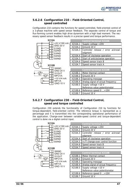
5.6.2.6 Configuration 210 – Field-Oriented Control,speed controlledConfiguration 210 contains the functions for speed-controlled, field-oriented control ofa 3-phase machine with speed sensor feedback. The separate control of torque andflux-forming current enables high drive dynamism with a high load moment. The necessaryspeed sensor feedback results in a precise speed and torque performance.+ -M-+-V+X210A1 +20 V/180 mA2 GND 20 V3 S1IND4 S2IND5 S3INDB6 S4INDA7 S5INDX210BS6IND1234567GND 20 VS1OUTMFO1A+10 V/4 mAMFI1AGND 10 VControl terminal X210AX210A.1 Supply voltage +20VX210A.2 Ground 20 VX210A.3 Controller release / error acknowledgmentX210A.4 Start of clockwise operationX210A.5 Start of anticlockwise operationX210A.6 Speed sensor track BX210A.7 Speed sensor track AControl terminal X210BX210B.1 Motor thermal contactX210B.2 Ground 20 VX210B.3 <strong>Operating</strong> messageX210B.4 Analog signal of actual frequencyX210B.5 Supply voltage +10 VReference value potentiometerX210B.6 Reference speed 0 ...+10VX210B.7 Ground 10 V5.6.2.7 Configuration 230 – Field-Oriented Control,speed and torque controlledConfiguration 230 extends the functionality of Configuration 210 by functions fortorque-dependent, field-oriented control. The reference torque is represented as apercentage and it is transmitted into the corresponding operational performance ofthe application. Change-over between variable-speed control and torque-dependentcontrol is done via a digital control input.+ -M-+-V+X210A1 +20 V/180 mA2 GND 20 V3 S1IND4 S2IND5 S3INDB6 S4INDA7 S5INDX210BS6IND1234567GND 20 VS1OUTMFO1A+10 V/4 mAMFI1AGND 10 VControl terminal X210AX210A.1 Supply voltage +20VX210A.2 Ground 20 VX210A.3 Controller release / error acknowledgmentX210A.4 Start of clockwise operationX210A.5 n-/T change-over control functionX210A.6 Speed sensor track BX210A.7 Speed sensor track AControl terminal X210BX210B.1 Motor thermal contactX210B.2 Ground 20 VX210B.3 <strong>Operating</strong> messageX210B.4 Analog signal of actual frequencyX210B.5 Supply voltage +10 VReference value potentiometerX210B.6 Reference speed 0 ...+10VX210B.7 Ground 10 V02/06 47