Operating Instruction - Frequency Inverter 230V / 400V ... - opis.cz
Operating Instruction - Frequency Inverter 230V / 400V ... - opis.cz
Operating Instruction - Frequency Inverter 230V / 400V ... - opis.cz
- No tags were found...

You also want an ePaper? Increase the reach of your titles
YUMPU automatically turns print PDFs into web optimized ePapers that Google loves.
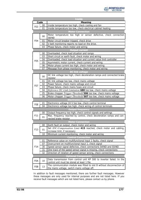
InsideCodeMeaningF0300 Inside temperature too high, check cooling and fan01 Inside temperature too low, check electrical cabinet heatingMotor Connection00Motor temperature too high or sensor defective, check connectionS6INDF04 01 Motor circuit breaker tripped, check drive02 V-belt monitoring reports no load on the drive.03 Phase failure, check motor and wiringOutput current00 Overloaded, check load situation and ramps03 Short circuit or earth fault, check motor and wiringF0504 Overloaded, check load situation and current value limit controller05 Asymmetric motor current, check current and wiring06 Motor phase current too high, check motor and wiring07 Message from phase monitoring, check motor and wiringDC link voltage00DC link voltage too high, check deceleration ramps and connected brakeresistor01 DC link voltage too low, check mains voltageF0702 Power failure, check mains voltage and circuit03 Phase failure, check mains fuses and circuit04 Reference DC-Link Limitation 680 too low, check mains voltage05 Brake chopper Trigger Threshold 506 too low, check mains voltage06 Motor chopper Trigger Threshold 507 too low, check mains voltageElectronics voltageF0801 Electronics voltage 24 V too low, check control terminal04 Electronics voltage too high, check wiring of control terminalsOutput frequency00 Output frequency too high, check control signals and settingsF11 Max. frequency reached by control, check deceleration ramps and connectedbrake resistor01Motor Connection00 Earth fault on output, check motor and wiringF13 01Set IDC-Compensation Limit 415 reached, check motor and cabling,increase limit, if necessary10 Minimum current monitoring, check motor and wiringControl Connection01 Reference value on multifunctional input 1 faulty, check signal07 Overcurrent on multifunctional input 1, check signalF14 30 Speed sensor signal defective, check connections S4IND and S5IND31 One track of the speed sensor signal is missing, check connections32 Direction of rotation of speed sensor wrong, check connectionsOptional ComponentsF0A 10Data transmission from control unit KP 500 to inverter failed. In thecontrol unit must be stored at least 1 file.F0B 13The communication module was fitted to slot B without disconnection ofthe mains voltage, switch mains voltage off.In addition to fault messages mentioned, there are further fault messages. Howeverthese messages are only used for internal purposes and are not listed here. If youreceive fault messages which are not listed here, please contact us by phone.02/06 177