Operating Instruction - Frequency Inverter 230V / 400V ... - opis.cz
Operating Instruction - Frequency Inverter 230V / 400V ... - opis.cz
Operating Instruction - Frequency Inverter 230V / 400V ... - opis.cz
- No tags were found...

You also want an ePaper? Increase the reach of your titles
YUMPU automatically turns print PDFs into web optimized ePapers that Google loves.
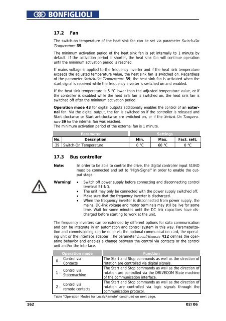
17.2 FanThe switch-on temperature of the heat sink fan can be set via parameter Switch-OnTemperature 39.The minimum activation period of the heat sink fan is set internally to 1 minute bydefault. If the activation period is shorter, the heat sink fan will continue operationuntil the minimum activation period is reached.If mains voltage is applied to the frequency inverter and if the heat sink temperatureexceeds the adjusted temperature value, the heat sink fan is switched on. Regardlessof the parameter Switch-On Temperature 39, the heat sink fan is activated when thestart signal is received while the frequency inverter is switched on and enabled.If the heat sink temperature is 5 °C lower than the adjusted temperature value, or ifthe controller is disabled while the heat sink fan is switched on, the heat sink fan isswitched off after the minimum activation period.Operation mode 43 for digital outputs additionally enables the control of an externalfan. Via the digital output, the fan is switched on if the controller is released andStart clockwise or Start anticlockwise are switched on, or if the Switch-On Temperature39 for the internal fan was reached.The minimum activation period of the external fan is 1 minute.ParameterSettingsNo. Description Min. Max. Fact. sett.39 Switch-On Temperature 0 °C 60 °C 0 °C17.3 Bus controllerNote:In order to be able to control the drive, the digital controller input S1INDmust be connected and set to "High-Signal" in order to enable the outputstage.Warning! • Switch off power supply before connecting and disconnecting controlterminal S1IND.• The unit may only be connected with the power supply switched off.• Make sure that the frequency inverter is discharged.• When the frequency inverter is disconnected from power supply, themains, DC-link voltage and motor terminals may still be live for sometime. Wait for some minutes until the DC link capacitors have dischargedbefore starting to work at the unit.The frequency inverters can be extended by different options for data communicationand can be integrate in an automation and control system in this way. Parameterizationand commissioning can be done via the optional communication card, the operatingunit or the interface adapter. The parameter Local/Remote 412 defines the operatingbehavior and enables a change between the control via contacts or the controlunit and/or the interface.Operation modeFunctionControl viaThe Start and Stop commands as well as the direction of0 -Contactsrotation are controlled via digital signals.The Start and Stop commands as well as the direction ofControl via1 - rotation are controlled via the DRIVECOM State machineStatemachineof the communication interface.The Start and Stop commands as well as the direction ofControl via2 - rotation are controlled via logic signals through theremote contactscommunication protocol.Table "Operation Modes for Local/Remote" continued on next page.162 02/06