Operating Instruction - Frequency Inverter 230V / 400V ... - opis.cz
Operating Instruction - Frequency Inverter 230V / 400V ... - opis.cz
Operating Instruction - Frequency Inverter 230V / 400V ... - opis.cz
- No tags were found...

You also want an ePaper? Increase the reach of your titles
YUMPU automatically turns print PDFs into web optimized ePapers that Google loves.
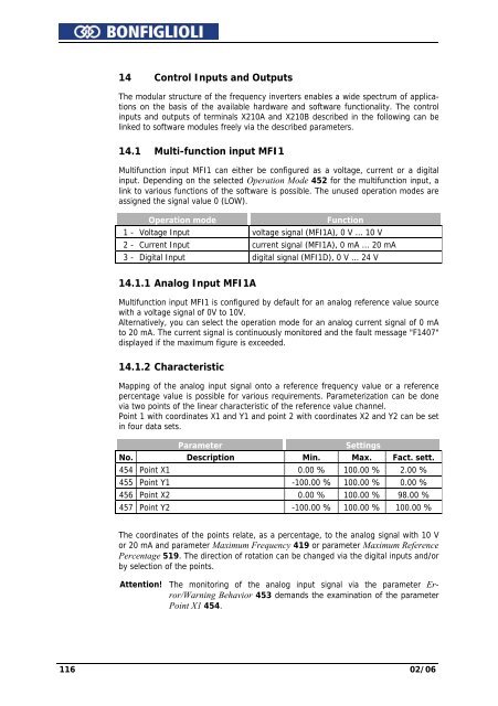
14 Control Inputs and OutputsThe modular structure of the frequency inverters enables a wide spectrum of applicationson the basis of the available hardware and software functionality. The controlinputs and outputs of terminals X210A and X210B described in the following can belinked to software modules freely via the described parameters.14.1 Multi-function input MFI1Multifunction input MFI1 can either be configured as a voltage, current or a digitalinput. Depending on the selected Operation Mode 452 for the multifunction input, alink to various functions of the software is possible. The unused operation modes areassigned the signal value 0 (LOW).Operation modeFunction1 - Voltage Input voltage signal (MFI1A), 0 V ... 10 V2 - Current Input current signal (MFI1A), 0 mA ... 20 mA3 - Digital Input digital signal (MFI1D), 0 V ... 24 V14.1.1 Analog Input MFI1AMultifunction input MFI1 is configured by default for an analog reference value sourcewith a voltage signal of 0V to 10V.Alternatively, you can select the operation mode for an analog current signal of 0 mAto 20 mA. The current signal is continuously monitored and the fault message "F1407"displayed if the maximum figure is exceeded.14.1.2 CharacteristicMapping of the analog input signal onto a reference frequency value or a referencepercentage value is possible for various requirements. Parameterization can be donevia two points of the linear characteristic of the reference value channel.Point 1 with coordinates X1 and Y1 and point 2 with coordinates X2 and Y2 can be setin four data sets.ParameterSettingsNo. Description Min. Max. Fact. sett.454 Point X1 0.00 % 100.00 % 2.00 %455 Point Y1 -100.00 % 100.00 % 0.00 %456 Point X2 0.00 % 100.00 % 98.00 %457 Point Y2 -100.00 % 100.00 % 100.00 %The coordinates of the points relate, as a percentage, to the analog signal with 10 Vor 20 mA and parameter Maximum <strong>Frequency</strong> 419 or parameter Maximum ReferencePercentage 519. The direction of rotation can be changed via the digital inputs and/orby selection of the points.Attention! The monitoring of the analog input signal via the parameter Error/WarningBehavior 453 demands the examination of the parameterPoint X1 454.116 02/06