Operating Instruction - Frequency Inverter 230V / 400V ... - opis.cz
Operating Instruction - Frequency Inverter 230V / 400V ... - opis.cz
Operating Instruction - Frequency Inverter 230V / 400V ... - opis.cz
- No tags were found...

Create successful ePaper yourself
Turn your PDF publications into a flip-book with our unique Google optimized e-Paper software.
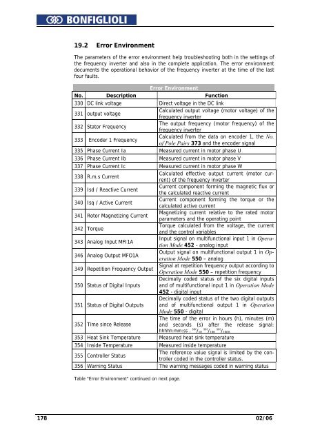
19.2 Error EnvironmentThe parameters of the error environment help troubleshooting both in the settings ofthe frequency inverter and also in the complete application. The error environmentdocuments the operational behavior of the frequency inverter at the time of the lastfour faults.Error EnvironmentNo. Description Function330 DC link voltage Direct voltage in the DC link331 output voltageCalculated output voltage (motor voltage) of thefrequency inverter332 Stator <strong>Frequency</strong>The output frequency (motor frequency) of thefrequency inverter333 Encoder 1 <strong>Frequency</strong>Calculated from the data on encoder 1, the No.of Pole Pairs 373 and the encoder signal335 Phase Current Ia Measured current in motor phase U336 Phase Current Ib Measured current in motor phase V337 Phase Current Ic Measured current in motor phase W338 R.m.s CurrentCalculated effective output current (motor current)of the frequency inverter339 Isd / Reactive CurrentCurrent component forming the magnetic flux orthe calculated reactive current340 Isq / Active CurrentCurrent component forming the torque or thecalculated active current341 Rotor Magnetizing CurrentMagnetizing current relative to the rated motorparameters and the operating point342 TorqueTorque calculated from the voltage, the currentand the control variables343 Analog Input MFI1AInput signal on multifunctional input 1 in OperationMode 452 - analog input346 Analog Output MFO1AOutput signal on multifunctional output 1 in OperationMode 550 – analog349 Repetition <strong>Frequency</strong> OutputSignal at repetition frequency output according toOperation Mode 550 – repetition frequencyDecimally coded status of the six digital inputs350 Status of Digital Inputs and of multifunctional input 1 in Operation Mode452 - digital inputDecimally coded status of the two digital outputs351 Status of Digital Outputs and of multifunctional output 1 in OperationMode 550 - digitalThe time of the error in hours (h), minutes (m)352 Time since Releaseand seconds (s) after the release signal:hhhhh:mm:ss . sec / sec 10 / sec 100 / 1000353 Heat Sink Temperature Measured heat sink temperature354 Inside Temperature Measured inside temperature355 Controller StatusThe reference value signal is limited by the controllercoded in the controller status.356 Warning Status The warning messages coded in warning statusTable "Error Environment" continued on next page.178 02/06