- Page 1:
INDUSTRYPROCESSAND AUTOMATION SOLUT
- Page 4 and 5:
TABLE OF CONTENTS1. General Safety
- Page 6 and 7:
TABLE OF CONTENTS7 Commissioning of
- Page 8 and 9:
TABLE OF CONTENTS13.10 Motor Potent
- Page 10 and 11:
TABLE OF CONTENTS19 Error Protocol.
- Page 12 and 13:
1.2 Purpose of the Frequency Invert
- Page 14 and 15:
2 Scope of SupplyThanks to the modu
- Page 16 and 17:
2.3 Frequency Inverter (18.5 up to
- Page 18 and 19:
3 Technical Data3.1 Frequency Inver
- Page 20 and 21:
3.3 Frequency Inverter 400 V (5.5 u
- Page 22 and 23:
3.5 Frequency Inverter 400 V (37.0
- Page 24 and 25:
4 Mechanical InstallationThe freque
- Page 26 and 27:
4.2 Frequency Inverter (5.5 to 15.0
- Page 28 and 29:
4.4 Frequency inverter (37.0 up to
- Page 30 and 31:
5.1 EMC InformationThe frequency in
- Page 32 and 33:
5.3 Mains ConnectionThe mains fuses
- Page 34 and 35:
5.3.3 Frequency Inverter (18.5 up t
- Page 36 and 37:
5.4 Motor ConnectionThe connection
- Page 38 and 39:
5.4.2 Frequency Inverter (5.5 up to
- Page 40 and 41:
5.4.4 Frequency Inverter (37.0 up t
- Page 42 and 43:
5.5.2 Frequency Inverter (5.5 up to
- Page 44 and 45:
5.6 Control TerminalsThe control an
- Page 46 and 47:
5.6.2 Control Terminals - Terminal
- Page 48 and 49:
5.6.2.4 Configuration 411 - Sensorl
- Page 50 and 51:
5.7 Optional ComponentsThanks to th
- Page 54 and 55:
6.4 Parameter Menu (PARA)The parame
- Page 56 and 57:
Function - ActOnly the active param
- Page 58 and 59:
6.5.6 Error MessagesThe copy functi
- Page 60 and 61:
Activation via CM Communication Mod
- Page 62 and 63:
6.8 Controlling the Motor via the C
- Page 64 and 65:
7 Commissioning of the Frequency In
- Page 66 and 67:
7.2.2 Data SetThe data set change-o
- Page 68 and 69:
101 -104 -Operation modeSingle eval
- Page 70 and 71:
Warning!Switch off power supply bef
- Page 72 and 73:
7.2.8.2 Set points at multi-functio
- Page 74 and 75:
Operation mode24 - Check Machine Da
- Page 76 and 77:
8.3 Inverter Software VersionThe fi
- Page 78 and 79:
In the table, you will find a list
- Page 80 and 81:
9 Machine DataThe input of the mach
- Page 82 and 83:
9.2.4 Rated Slip Correction FactorT
- Page 84 and 85:
10 System DataThe various control f
- Page 86 and 87:
Operation mode3 -4 -12 -14 -Magneti
- Page 88 and 89:
11.2 Stopping BehaviorThe stopping
- Page 90 and 91:
11.2.1 Switch-Off ThresholdThe Swit
- Page 92 and 93: 11.5 Search RunThe synchronization
- Page 94: 11.6.1 Reference PositioningThe fee
- Page 97 and 98: 11.6.2 Axis PositioningFor axis pos
- Page 99 and 100: 12 Error and warning behaviorOperat
- Page 101 and 102: 12.6 Motor TemperatureThe configura
- Page 103 and 104: 13 Reference ValuesThe ACT series f
- Page 105 and 106: 13.4.1 Block DiagramThe following t
- Page 107 and 108: 13.5 Reference Percentage ChannelTh
- Page 109 and 110: 13.6 Fixed Reference ValuesThe fixe
- Page 111 and 112: The ramps for Emergency Stop Clockw
- Page 113 and 114: 13.8 Percentage Value RampsThe perc
- Page 115 and 116: The Operation Mode 474 of the motor
- Page 117 and 118: 13.11 Repetition frequency inputThe
- Page 119 and 120: The following characteristic is set
- Page 121 and 122: The default Minimum Frequency 418 o
- Page 123 and 124: 14.2.1 Analog Output MFO1ABy defaul
- Page 125 and 126: 14.3 Digital OutputsThe OP. Mode Di
- Page 127 and 128: 14.3.4 Open brakeThe Open brake fun
- Page 129 and 130: Operation modeFunctionThe DC link v
- Page 131 and 132: Operation modeFunction158 - Timer 1
- Page 133 and 134: 14.4.1 Start commandThe parameters
- Page 135 and 136: 14.4.8 Fixed Value Change-OverDepen
- Page 137 and 138: 14.5.1.1 Time ConstantThe logic seq
- Page 139 and 140: The switch-on and switch-off thresh
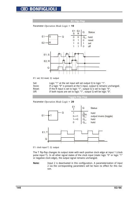
- Page 141: Examples of the logic functions dep
- Page 145 and 146: The default Cut-Off Voltage 603 (UC
- Page 147 and 148: 16.2 Voltage controllerThe voltage
- Page 149 and 150: ParameterSettingsNo. Description Mi
- Page 151 and 152: 16.3 Technology ControllerThe techn
- Page 153 and 154: Structural image:Technology control
- Page 155 and 156: Behavior in generator operation:If
- Page 157 and 158: 16.5.2.1 Limit Value SourcesThe lim
- Page 159 and 160: −−−The output value of the co
- Page 161 and 162: Optimization of the controller para
- Page 163 and 164: 17 Special FunctionsThe configurabl
- Page 165 and 166: Operation modeFunctionControl via K
- Page 167 and 168: 17.4.1 Dimensioning of Brake Resist
- Page 169 and 170: Multiple motor operationParameter O
- Page 171 and 172: 17.7.2 Temperature AdjustmentThe fi
- Page 173 and 174: 18 Actual ValuesThe various control
- Page 175 and 176: 18.3 Actual Value MemoryThe assessm
- Page 177 and 178: 18.4.2 Volume Flow and PressureThe
- Page 179 and 180: InsideCodeMeaningF0300 Inside tempe
- Page 181 and 182: Error Environment357 Int. Value 1 S
- Page 183 and 184: A decimal value is displayed, indic
- Page 185 and 186: 21 Parameter ListThe parameter list
- Page 187 and 188: Error EnvironmentNo. Description Un
- Page 189 and 190: Controlled commissioningNo. Descrip
- Page 191 and 192: Fixed FrequenciesNo. Description Un
- Page 193 and 194:
Search RunNo. Description Unit Sett
- Page 195 and 196:
INDUSTRY PROCESSAND AUTOMATION SOLU