Operating Instruction - Frequency Inverter 230V / 400V ... - opis.cz
Operating Instruction - Frequency Inverter 230V / 400V ... - opis.cz
Operating Instruction - Frequency Inverter 230V / 400V ... - opis.cz
- No tags were found...

Create successful ePaper yourself
Turn your PDF publications into a flip-book with our unique Google optimized e-Paper software.
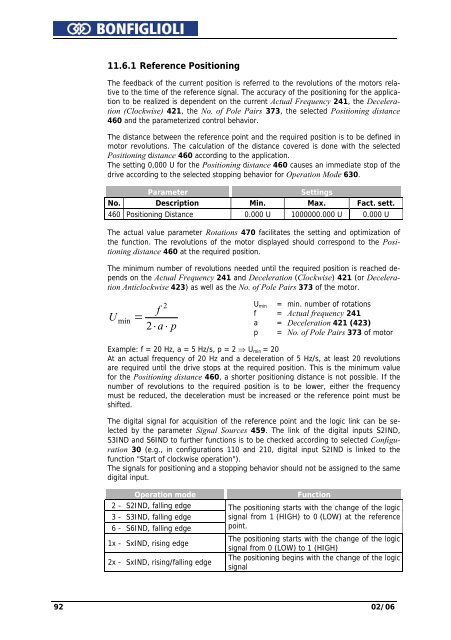
11.6.1 Reference PositioningThe feedback of the current position is referred to the revolutions of the motors relativeto the time of the reference signal. The accuracy of the positioning for the applicationto be realized is dependent on the current Actual <strong>Frequency</strong> 241, the Deceleration(Clockwise) 421, the No. of Pole Pairs 373, the selected Positioning distance460 and the parameterized control behavior.The distance between the reference point and the required position is to be defined inmotor revolutions. The calculation of the distance covered is done with the selectedPositioning distance 460 according to the application.The setting 0,000 U for the Positioning distance 460 causes an immediate stop of thedrive according to the selected stopping behavior for Operation Mode 630.ParameterSettingsNo. Description Min. Max. Fact. sett.460 Positioning Distance 0.000 U 1000000.000 U 0.000 UThe actual value parameter Rotations 470 facilitates the setting and optimization ofthe function. The revolutions of the motor displayed should correspond to the Positioningdistance 460 at the required position.The minimum number of revolutions needed until the required position is reached dependson the Actual <strong>Frequency</strong> 241 and Deceleration (Clockwise) 421 (or DecelerationAnticlockwise 423) as well as the No. of Pole Pairs 373 of the motor.Umin= f22 ⋅ a ⋅ pU min = min. number of rotationsf = Actual frequency 241a = Deceleration 421 (423)p = No. of Pole Pairs 373 of motorExample: f = 20 Hz, a = 5 Hz/s, p = 2 ⇒ U min = 20At an actual frequency of 20 Hz and a deceleration of 5 Hz/s, at least 20 revolutionsare required until the drive stops at the required position. This is the minimum valuefor the Positioning distance 460, a shorter positioning distance is not possible. If thenumber of revolutions to the required position is to be lower, either the frequencymust be reduced, the deceleration must be increased or the reference point must beshifted.The digital signal for acquisition of the reference point and the logic link can be selectedby the parameter Signal Sources 459. The link of the digital inputs S2IND,S3IND and S6IND to further functions is to be checked according to selected Configuration30 (e.g., in configurations 110 and 210, digital input S2IND is linked to thefunction "Start of clockwise operation").The signals for positioning and a stopping behavior should not be assigned to the samedigital input.Operation mode2 - S2IND, falling edge3 - S3IND, falling edge6 - S6IND, falling edge1x - SxIND, rising edge2x - SxIND, rising/falling edgeFunctionThe positioning starts with the change of the logicsignal from 1 (HIGH) to 0 (LOW) at the referencepoint.The positioning starts with the change of the logicsignal from 0 (LOW) to 1 (HIGH)The positioning begins with the change of the logicsignal92 02/06