Operating Instruction - Frequency Inverter 230V / 400V ... - opis.cz
Operating Instruction - Frequency Inverter 230V / 400V ... - opis.cz
Operating Instruction - Frequency Inverter 230V / 400V ... - opis.cz
- No tags were found...
You also want an ePaper? Increase the reach of your titles
YUMPU automatically turns print PDFs into web optimized ePapers that Google loves.
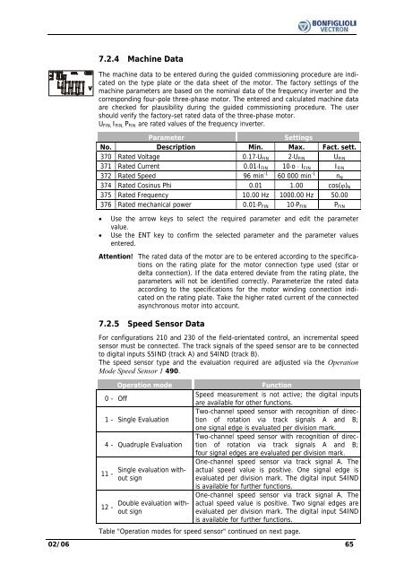
7.2.4 Machine DataThe machine data to be entered during the guided commissioning procedure are indicatedon the type plate or the data sheet of the motor. The factory settings of themachine parameters are based on the nominal data of the frequency inverter and thecorresponding four-pole three-phase motor. The entered and calculated machine dataare checked for plausibility during the guided commissioning procedure. The usershould verify the factory-set rated data of the three-phase motor.U FIN, I FIN, P FIN are rated values of the frequency inverter.ParameterSettingsNo. Description Min. Max. Fact. sett.370 Rated Voltage 0.17⋅U FIN 2⋅U FIN U FIN371 Rated Current 0.01⋅I FIN 10⋅o ⋅ I FIN I FIN372 Rated Speed 96 min -1 60 000 min -1 n N374 Rated Cosinus Phi 0.01 1.00 cos(ϕ) N375 Rated <strong>Frequency</strong> 10.00 Hz 1000.00 Hz 50.00376 Rated mechanical power 0.01⋅P FIN 10⋅P FIN P FIN• Use the arrow keys to select the required parameter and edit the parametervalue.• Use the ENT key to confirm the selected parameter and the parameter valuesentered.Attention! The rated data of the motor are to be entered according to the specificationson the rating plate for the motor connection type used (star ordelta connection). If the data entered deviate from the rating plate, theparameters will not be identified correctly. Parameterize the rated dataaccording to the specifications for the motor winding connection indicatedon the rating plate. Take the higher rated current of the connectedasynchronous motor into account.7.2.5 Speed Sensor DataFor configurations 210 and 230 of the field-orientated control, an incremental speedsensor must be connected. The track signals of the speed sensor are to be connectedto digital inputs S5IND (track A) and S4IND (track B).The speed sensor type and the evaluation required are adjusted via the OperationMode Speed Sensor 1 490.Operation modeFunctionSpeed measurement is not active; the digital inputs0 - Offare available for other functions.Two-channel speed sensor with recognition of directionof rotation via track signals A and B;1 - Single Evaluationone signal edge is evaluated per division mark.Two-channel speed sensor with recognition of directionof rotation via track signals A and B;4 - Quadruple Evaluationfour signal edges are evaluated per division mark.One-channel speed sensor via track signal A. TheSingle evaluation withoutsignevaluated per division mark. The digital input S4INDactual speed value is positive. One signal edge is11 -is available for further functions.One-channel speed sensor via track signal A. TheDouble evaluation withoutsignevaluated per division mark. The digital input S4INDactual speed value is positive. Two signal edges are12 -is available for further functions.Table "Operation modes for speed sensor" continued on next page.02/06 65


