Operating Instruction - Frequency Inverter 230V / 400V ... - opis.cz
Operating Instruction - Frequency Inverter 230V / 400V ... - opis.cz
Operating Instruction - Frequency Inverter 230V / 400V ... - opis.cz
- No tags were found...
Create successful ePaper yourself
Turn your PDF publications into a flip-book with our unique Google optimized e-Paper software.
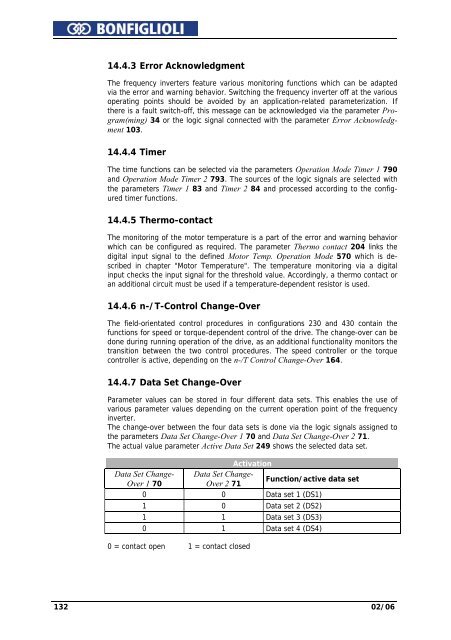
14.4.3 Error AcknowledgmentThe frequency inverters feature various monitoring functions which can be adaptedvia the error and warning behavior. Switching the frequency inverter off at the variousoperating points should be avoided by an application-related parameterization. Ifthere is a fault switch-off, this message can be acknowledged via the parameter Program(ming)34 or the logic signal connected with the parameter Error Acknowledgment103.14.4.4 TimerThe time functions can be selected via the parameters Operation Mode Timer 1 790and Operation Mode Timer 2 793. The sources of the logic signals are selected withthe parameters Timer 1 83 and Timer 2 84 and processed according to the configuredtimer functions.14.4.5 Thermo-contactThe monitoring of the motor temperature is a part of the error and warning behaviorwhich can be configured as required. The parameter Thermo contact 204 links thedigital input signal to the defined Motor Temp. Operation Mode 570 which is describedin chapter "Motor Temperature". The temperature monitoring via a digitalinput checks the input signal for the threshold value. Accordingly, a thermo contact oran additional circuit must be used if a temperature-dependent resistor is used.14.4.6 n-/T-Control Change-OverThe field-orientated control procedures in configurations 230 and 430 contain thefunctions for speed or torque-dependent control of the drive. The change-over can bedone during running operation of the drive, as an additional functionality monitors thetransition between the two control procedures. The speed controller or the torquecontroller is active, depending on the n-/T Control Change-Over 164.14.4.7 Data Set Change-OverParameter values can be stored in four different data sets. This enables the use ofvarious parameter values depending on the current operation point of the frequencyinverter.The change-over between the four data sets is done via the logic signals assigned tothe parameters Data Set Change-Over 1 70 and Data Set Change-Over 2 71.The actual value parameter Active Data Set 249 shows the selected data set.ActivationData Set Change- Data Set Change-Over 1 70Over 2 71Function/active data set0 0 Data set 1 (DS1)1 0 Data set 2 (DS2)1 1 Data set 3 (DS3)0 1 Data set 4 (DS4)0 = contact open 1 = contact closed132 02/06


