Balancing valve with flow meter - Caleffi
Balancing valve with flow meter - Caleffi
Balancing valve with flow meter - Caleffi
- No tags were found...

Create successful ePaper yourself
Turn your PDF publications into a flip-book with our unique Google optimized e-Paper software.
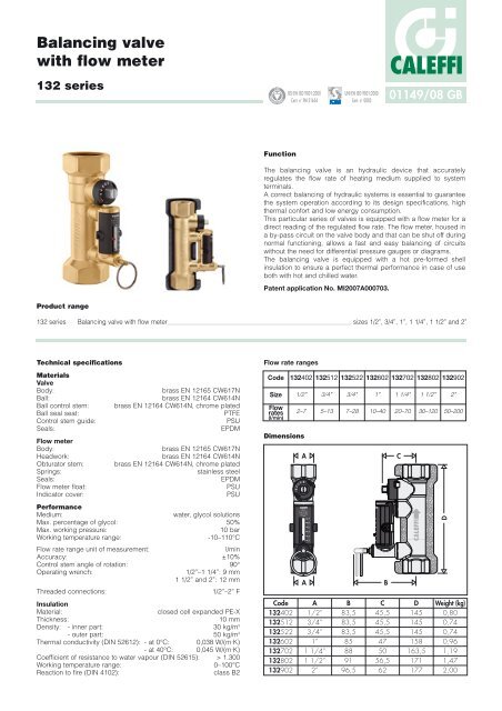
<strong>Balancing</strong> <strong>valve</strong><strong>with</strong> <strong>flow</strong> <strong>meter</strong>132 seriesREGI STEREDBSI EN ISO 9001:2000Cert. n° FM 21654UNI EN ISO 9001:2000Cert. n° 0003CALEFFI01149/08 GBFunctionThe balancing <strong>valve</strong> is an hydraulic device that accuratelyregulates the <strong>flow</strong> rate of heating medium supplied to systemterminals.A correct balancing of hydraulic systems is essential to guaranteethe system operation according to its design specifications, highthermal confort and low energy consumption.This particular series of <strong>valve</strong>s is equipped <strong>with</strong> a <strong>flow</strong> <strong>meter</strong> for adirect reading of the regulated <strong>flow</strong> rate. The <strong>flow</strong> <strong>meter</strong>, housed ina by-pass circuit on the <strong>valve</strong> body and that can be shut off duringnormal functioning, allows a fast and easy balancing of circuits<strong>with</strong>out the need for differential pressure gauges or diagrams.The balancing <strong>valve</strong> is equipped <strong>with</strong> a hot pre-formed shellinsulation to ensure a perfect thermal performance in case of useboth <strong>with</strong> hot and chilled water.Patent application No. MI2007A000703.Product range132 series <strong>Balancing</strong> <strong>valve</strong> <strong>with</strong> <strong>flow</strong> <strong>meter</strong> sizes 1/2”, 3/4”, 1”, 1 1/4”, 1 1/2” and 2”Technical specificationsMaterialsValveBody:brass EN 12165 CW617NBall:brass EN 12164 CW614NBall control stem: brass EN 12164 CW614N, chrome platedBall seal seat:PTFEControl stem guide:PSUSeals:EPDMFlow <strong>meter</strong>Body:brass EN 12165 CW617NHeadwork:brass EN 12164 CW614NObturator stem: brass EN 12164 CW614N, chrome platedSprings:stainless steelSeals:EPDMFlow <strong>meter</strong> float:PSUIndicator cover:PSUPerformanceMedium:water, glycol solutionsMax. percentage of glycol: 50%Max. working pressure:10 barWorking temperature range:-10–110°CFlow rate range unit of measurement:l/minAccuracy: ±10%Control stem angle of rotation: 90°Operating wrench:1/2”–1 1/4”: 9 mm1 1/2” and 2”: 12 mmThreaded connections:1/2”–2” FInsulationMaterial:closed cell expanded PE-XThickness:10 mmDensity: - inner part: 30 kg/m 3- outer part: 50 kg/m 3Thermal conductivity (DIN 52612): - at 0°C: 0,038 W/(m·K)- at 40°C: 0,045 W/(m·K)Coefficient of resistance to water vapour (DIN 52615): > 1.300Working temperature range:0–100°CReaction to fire (DIN 4102):class B2Flow rate rangesCode 132402 132512 132522 132602 132702 132802 132902Size 1/2” 3/4” 3/4” 1” 1 1/4” 1 1/2” 2”Flowrates(l/min)DimensionsCode1324021325121325221326021327021328021329022–7 5–13 7–28 10–40 20–70 30–120 50–200ACALEFFI15barA765432A1/2”3/4”3/4”1”1 1/4”1 1/2”2”B83,583,583,585889196,5BC45,545,545,5475056,562CD145145145158163,5171177DWeight (kg)0,800,740,740,961,191,472,00
765432234567234567Advantages of balanced circuitsBalanced circuits have the following principal benefits:1. The system terminals operate correctly in heating, cooling anddehumidification <strong>with</strong>out waste of energy and provide a bettercomfort.2. The pumps run in their zone of highest efficiency, thus reducingthe risk of overheating and excessive wear.3. Too high medium speeds, which can result in noise andabrasion, are avoided.4. The differential pressures acting on the regulation <strong>valve</strong>s arelimited in value, thus preventing faulty operation.Operating principleThe balancing <strong>valve</strong> is an hydraulic device that allows to regulatethe medium <strong>flow</strong> rate passing through.The regulating action is made by a ball obturator (1), operated bya control stem (2). The <strong>flow</strong> rate is controlled by means of a <strong>flow</strong><strong>meter</strong> (3) housed in a by-pass circuit, on the <strong>valve</strong> body, that canbe shut off during normal functioning. The <strong>flow</strong> rate value isindicated by a metal sphere (4), sliding <strong>with</strong>in a transparent guide(5), marked alongside by a graduated scale (6).115321765432536454Construction detailsFlow <strong>meter</strong>The <strong>flow</strong> rate value is displayeddirectly by a <strong>flow</strong> <strong>meter</strong> housedin a by-pass circuit on the <strong>valve</strong>body, automatically shut-offduring normal functioning.The use of a <strong>flow</strong> <strong>meter</strong> greatlysimplifies the process of systembalancing, since the <strong>flow</strong> ratecan be measured andcontrolled at any time and thereis no need for differentialpressure gauges or referencecharts.The provision of a <strong>flow</strong> <strong>meter</strong>also means that it is notanymore necessary to calculate<strong>valve</strong> settings at the systemdesign stage.The advantages of this solutioncan be explained as significanttime and cost saving, becausethe traditional balancing devicepresetting, performed byqualified technicians, is a longand difficult procedure.2Flow <strong>meter</strong> obturatorThe obturator (1) opens and shuts the circuit between the <strong>flow</strong><strong>meter</strong> and the <strong>valve</strong>. The obturator can be easily opened by pullingthe ring (2), and is closed automatically, after completion of theprocedure, by theinternal spring (3). The spring and the EPDM seal(4) guarantee over time a perfect circuit closure during normalfunctioning.The operating ring (2) is made of a material <strong>with</strong> low thermalconductivity to avoid burns if the <strong>flow</strong> <strong>meter</strong> is opened while hotmedium is passing through the <strong>valve</strong>.Ball/magnet indicatorThe ball (4) that indicates the <strong>flow</strong> rate value isnot in direct contact <strong>with</strong> the thermal mediumpassing through the <strong>flow</strong> <strong>meter</strong>.Thanks to an effective and innovative measuringsystem, the ball slides up and down in a cylinder(5) that is actually separate from the body of the<strong>flow</strong> <strong>meter</strong>. The ball is moved by a magnet (6)fixed to a float (7).This means that the <strong>flow</strong> rate indication systemremains perfectly clean and provides reliablereadings over time.43125764
765432765432325476765432Complete closing and opening of the <strong>valve</strong>The <strong>valve</strong> can be completely closed and opened.A slot on the obturator stem indicates the status of the <strong>valve</strong>.When the control stemis turned fully clockwise Completely closed Completely openand the slot liesperpendicular to theaxis of the <strong>valve</strong>, the<strong>valve</strong> is fully closed (A).When the controlstem is turned fullyanti-clockwise and theslot lies parallel to theaxis of the <strong>valve</strong>, the<strong>valve</strong> is fully open (B).A BInsulationThe 132 series balancing <strong>valve</strong>is supplied complete <strong>with</strong> hotpre-formed insulation. Thissystem ensures not only perfectthermal insulation, but alsotightness to water vapour fromthe environment towards theinside. For these reasons, thistype of insulation can also beused in chilled water circuits asit prevents condensationforming on the surface of the<strong>valve</strong> body.Hydraulic characteristicsFlow rate adjustmentΔp (mm w.g.)15.0001/2”3/4”3/4”1”1 1/4”1 1/2”2”Δp (kPa)150The <strong>flow</strong> rate is adjusted by carrying out the following operations:10.0005.0002.0001005020A.With the aid of the indicator(1), mark the reference <strong>flow</strong>rate at which the <strong>valve</strong> has tobe set.B.Use the ring (2) to open theobturator that shuts off the<strong>flow</strong> of medium in the <strong>flow</strong><strong>meter</strong> (3) under normaloperating conditions.1.0001050020010050 100250 500 1.000 2.500 5.000 10.000 25.000150.000G (l/h)Code 132402 132512 132522 132602 132702 132802 132902Size 1/2” 3/4” 3/4” 1” 1 1/4” 1 1/2” 2”Flowrates 2–7 5–13 7–28 10–40 20–70 30–120 50–200(l/min)Kv (m 3 /h) 0,9 2,5 5,4 7,2 13,1 27,8 46,452132Kv <strong>valve</strong>s fully openCorrection for liquids <strong>with</strong> different densitiesFor fluids <strong>with</strong> a viscosity ≤3°E, e.g. water/glycol solutions <strong>with</strong> densitydifferent <strong>with</strong> respect to the water at 20°C (ρ = 1 kg/dm 3 ), to which theupper diagram refers, it should be considered that:- pressure drop (for sizing the pump) is determined by:Δpactual = Δpreference x ρglycol solution;- variation in <strong>flow</strong> rate measurement remains <strong>with</strong>in the specifiedaccuracy (±10%) for glycol percentages up to 50%.InstallationInstall the balancing <strong>valve</strong> in such a way to ensure free access tothe <strong>flow</strong> <strong>meter</strong> obturator, control stem and <strong>flow</strong> rate indicator.We recommend to install straight sections of pipe as shown in theillustration below to ensure accurate <strong>flow</strong> measurement.132 series 132 seriesPumpC.Keeping the obturator open, apply a wrench on the control stemof the <strong>valve</strong> (4) to adjust the <strong>flow</strong> rate. It is indicated by a metalball (5) that runs inside a transparent guide (6) marked by agraduated scale in l/min.4565D10DThe <strong>valve</strong> can be installed in any position by respecting the <strong>flow</strong>direction shown on the <strong>valve</strong> body. The <strong>valve</strong> can be installed eitherhorizontally or vertically.D.After completing the balancing, release the ring of the <strong>flow</strong> <strong>meter</strong>obturator that, thanks to an internal spring, will automatically goback into the closed position.
Application diagramsThe balancing <strong>valve</strong> <strong>with</strong> the <strong>flow</strong> <strong>meter</strong> should preferably be installed on the circuit return pipe.To adjust the <strong>flow</strong> rate to each riserTo balance circuits serving air conditioning unitssTo adjust the <strong>flow</strong> rate to each terminalTo balance the by-pass branch of outside compensatedcontrol circuitsTo balance zone branches in circuits <strong>with</strong> three-way <strong>valve</strong>sTo balance sanitary water distribution circuitsSPECIFICATION SUMMARIES132 series<strong>Balancing</strong> <strong>valve</strong> <strong>with</strong> <strong>flow</strong> <strong>meter</strong>. Threaded connections 1/2” (from 1/2” to 2”) F x F. Brass body. Brass ball. Brass ball controlstem, chrome plated. PTFE ball seal seat. PSU control stem guide. Brass <strong>flow</strong> <strong>meter</strong> body and headwork. Brass <strong>flow</strong> <strong>meter</strong>obturator control stem, chrome plated. Stainless steel <strong>flow</strong> <strong>meter</strong> springs. PSU <strong>flow</strong> <strong>meter</strong> float and indicator cover. EPDMseals. With pre-formed shell insulation in expanded closed cell PE-X. Medium water and glycol solutions. Maximumpercentage of glycol 50%. Maximum working pressure 10 bar. Working temperature range -10–110°C. Flow rate range unit ofmeasurement l/min. Accuracy ± 10%. Control stem angle of rotation 90°.We reserve the right to make changes and improvements to the products and related data in this publication, at any time and <strong>with</strong>out prior notice.CALEFFICALEFFI S.P.A. · I · 28010 FONTANETO D’AGOGNA (NO) · S.R. 229, N.25 · TEL. +39 0322 8491 R.A. · FAX +39 0322 863723· www.caleffi.com · info@caleffi.com ·© Copyright 2008 <strong>Caleffi</strong>