Install Instructions - Thermal Products Inc
Install Instructions - Thermal Products Inc
Install Instructions - Thermal Products Inc

Create successful ePaper yourself
Turn your PDF publications into a flip-book with our unique Google optimized e-Paper software.
MODEL EH ELECTRIC BOILEREH-08-135S through EH-40-135S 3 wire 120/208V, 120/240V single phaseEH-12-345S through EH-40-345S 4 wire 120/208V three phase WYEOPERATION AND INSTALLATION INSTRUCTIONSCONTENTS . . . . . . . . . . . . . . . . . . . . . . . . . . . . . . . . . . . .PAGEDescription . . . . . . . . . . . . . . . . . . . . . . . . . . . . . . . . . . . . . . . . .2Mounting . . . . . . . . . . . . . . . . . . . . . . . . . . . . . . . . . . . . . . . . . . .2Piping . . . . . . . . . . . . . . . . . . . . . . . . . . . . . . . . . . . . . . . . . . . . .2Air Eliminator and Expansion Tanks . . . . . . . . . . . . . . . . . .2Flow Switch . . . . . . . . . . . . . . . . . . . . . . . . . . . . . . . . . . . . .2Bypass . . . . . . . . . . . . . . . . . . . . . . . . . . . . . . . . . . . . . . . . .2Wiring (Warning: DO NOT turn on breakers on unit) . . . . . . . . .2Wall Thermostat Flow Switch and Circulator . . . . . . . . . . .2Service Connections and Electrical Ratings . . . . . . . . . . . .3Start-up . . . . . . . . . . . . . . . . . . . . . . . . . . . . . . . . . . . . . . . . . . . .6Fill System . . . . . . . . . . . . . . . . . . . . . . . . . . . . . . . . . . . . . .6Air Elimination . . . . . . . . . . . . . . . . . . . . . . . . . . . . . . . . . . .6Bypass Flow Adjustment . . . . . . . . . . . . . . . . . . . . . . . . . . .6Check for Proper Boiler and System Operation . . . . . . . . .6Operation (models equipped with seq. control system) . . . . . . .6Periodic Inspection . . . . . . . . . . . . . . . . . . . . . . . . . . . . . . . . . . .6IMPORTANT:This manual must be left with owner and should be hungon or adjacent to the boiler for reference.Publication No. EH-40Printed in U.S.A. 405Part No. 79-0820
DESCRIPTIONThe Monitron boiler is a low pressure hot water heating electricboiler. The heating elements are sheathed resistance type. Theheat exchanger is cast-iron. The heat exchanger is constructed,inspected, and stamped in accordance with Section IV of theAmerican Society of Mechanical Engineers (ASME) Boiler andPressure Vessel Code. In addition, the Monitron Boiler isequipped with a safety relief valve and an integral dual limit control,conforming to ASME requirements. The Monitron boiler isUnderwriters' Laboratories, <strong>Inc</strong>. listed.MOUNTINGThe Monitron is intended for wall mounting, utilizing the wallbrackets attached to the boiler (see Figure 1). Allow sufficientspace for piping and service. The boiler may be installed in anenclosed space (see Figure 1). The boiler must be INSTALLEDLEVEL.PIPINGAir Separator and Expansion TanksThe recommended piping arrangement is shown in Figures 2through 4. Note that there is a built-in air eliminator in the heatexchanger (air vent, however, is by others). A 1/8" air vent maybe used. Additional air vents should be installed at points justupstream from all drops in elevation of the piping system (highpoints).Flow SwitchA FLOW SWITCH MUST BE INSTALLED. It is intended to preventthe burnout of heater elements should the circulator fail, orshould air accumulate in the boiler due to faulty air elimination(see Table 3 for flow switch size required). FLOW SWITCHMUST BE INSTALLED IN HORIZONTAL POSITION.BypassThe bypass shown must be set so that a sufficient amount ofwater can circulate through the boiler when all zone valves areclosed. See Figure 3.Multi-zone BalancingRaise all zone thermostat settings and verify that all zone valvesare open (not bypassed). Close all electrical panels. Turn on 10amp control circuit breaker ONLY. Pump should operate. Notethe pressure reading on the pump discharge. Lower each zonethermostat setting to close corresponding zone valve. Adjust thecorresponding balancing valve to maintain pump discharge pressure.The pump discharge pressure should remain the samewhen all zones are in bypass or when all zones are open or anycombination of opened and closed. See Figure 4.WIRINGTo wire the electric boiler, perform the following procedures:1. Wall Thermostat Flow Switch and Circulator• All circuit breakers ahead of and at boiler must be OFF.Remove the Control Panel (left-hand front) Cover byremoving 5 screws from top, bottom and side flanges.• The right-hand compartment under the Control PanelCover contains a terminal board marked, "TTFF". Wire a2-wire 24V heating thermostat or the auxiliary end switchterminals of zone valves (see Figure 5) to "TT" at thistime. The "FF" terminals are for the flow switch. You maydraw the wires between the flow switch and the compartmentcontaining the "TTFF" terminal board but the wiresat the flow switch end may NOT be connected and theends should be taped. The flow switch circuit is a low voltagecircuit (see wiring diagram, Figure 5).• Wire the circulator and connect wires and conduit through1/2" K.O. provided on bottom left hand corner, to the terminalboard marked, "Circulator". Wire zone valve transformerto terminals "A" and "B" of this terminal board (seeFigure 6) if zone valves are used. Use 75°C. minimumwire, copper or aluminum.2
2. Service Connections and Electrical RatingsA. All circuit breakers ahead of and at boiler must beOFF. Remove the Service Connection Panel (right handfront). Cover by removing 5 screws from the top, bottomand side flanges (see wiring diagram on back of theService Connection Panel and Figure 5).B. Draw power feeder cable (75°C minimum) and conduitthrough service K.O. provided on side, top and bottom.C. Connect hot lines to main lugs on breaker base or to blackand red or to black, red and blue leads provided in servicecompartment. A ground lead should be drawn and wiredto the ground lug in the service compartment. If ratingplate indicates boiler is a single phase 3-wire or 3-phase4-wire model, draw a neutral wire #12 AWG maximum,75˚C. minimum and connect to neutral lug or white wirelead provided in service compartment. See Tables 1 and 2for lug sizes and current ratings.Table 1. Lug SizesMain * Lug Grounding Lug Wire SizeWire Size Small Holes Large HolesModel Phase CU-AL† CU-AL† CU AL†EH-40 1 2-250 MCM CU DO NOT USE 6-2/0EH-28 thru 32 1 2-250 MCM DO NOT USE 14-4 6-4EH-8 thru 24 1 6-2/0 14-8 14-4 6-4EH-8 thru 40 3 6-2/0 14-8 14-4 6-4Neutral Lug Wire Size: For 3-wire single phase and 4-wire 3 phase modelsequipped with circuit breakersSmall Holes: #14-12 Solid CU or AL † and #12 stranded CU or AL†Large Holes: #14-8 Solid CU, #10-4 Stranded CU and #6-4 AL †The neutral tap is for the circulator and control transformer. The maximum wire size ofthe neutral should not exceed 12 AWG in that 2" conduit accommodate 2 incomingpower feeders plus a neutral wire and a ground conductor for the large size models.* For models with circuit breakers only.† ALUMINUM conductors may be used, lug size, conduit size, ampacity and all applicablecodes permitting. However, aluminum conductors may NOT be used for model EH-40 single phase.Table 2. Current RatingsSINGLE PHASE 3 WIRE120/208V, 120/240V‡THREE PHASE, 4 WIRE120/208V-WYECIRCUIT ONLY‡Basic Heater Basic HeaterModel Amperes* Model Amperes†No. @240V No. @208VEH-8 33EH-10 42EH-12 50 EH-12 25EH-16 67 EH-16 38†EH-20 83 EH-20 48†EH-24 100 EH-24 60†EH-28 117 EH-28 60†EH-32 133 EH-32 73†EH-40 167 EH-40 95†Table 3. Flow Switch Size SelectionFlow SwitchMinimumModel McDonnell Pipe Length ofNo. & Miller No. Size Flow Switch*EH-40 FS8V 1-1/4” 8-1/2”EH-8 thru EH-32 FS4-3T3-1 1” 6-1/2”* Straight pipe upstream and downstream* For current values @ 208V, multiply current @ 240V by 0.867.† Leg with the highest value of line current of an unbalanced 3-phase load.‡ 125 VAC maximum rating of all hot conductors.3
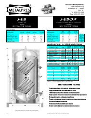
4NOTES:1. Optional blocking gate valve and hose end valve used (with drain valve) for fast fill and purge of system.IMPORTANT: Close bypass line valve (if used) during purging.2. Circulator should not be installed at lowest point of piping.3. There should be no elbows, tees, or change of pipe size for at least 5 diameters of pipe size (see Table 3) upstream and downstream of flow switch.Flow switch should always be mounted in the horizontal position. See Table 3.
START-UPNOTE: Make sure that all circuit breakers ahead of and at theboiler are OFF.Fill SystemSee Figures 2 through 4 for suggested purge valve and blockingvalve. If system is filled but not purged, radiators must be ventedindividually, to prevent air blocking of water flow. Fill approximately12 psi (cold water), whether automatic or manual fill isused. DO NOT apply full line pressure to system; boiler andrelief valve are rated at 30 or 50 psi (see rating plate). Suddenlyapplied main pressure can exceed 100 psi.Air EliminationDiaphragm tank and air vent valve are recommended, seeFigures 2 through 4. Air remaining in system will vent from theautomatic vent valve during system operation. Valve cap must beloose or removed to allow automatic venting. Open relief valvebriefly after filling to pressure, to make sure boiler is free of air.Bypass flow adjustment (Figure 3)Close bypass valve. Turn down all zone thermostats. Inspect allzone valves to be sure all are closed. Put a jumper on TT terminals.Close ALL panels and turn on the 15 AMP control circuitbreaker ONLY. Be certain that the flow switch wires are not connectedto the flow switch terminals and the ends of the wires aretaped. Connect the ohmmeter or other continuity tester acrossthe common terminal and the terminal that is normally open duringNO FLOW. Slowly open bypass valve until continuity testerlights or ohmmeter kicks to zero: flow switch now has closedcontacts, indicating required minimum bypass flow rate whenpiping circuits are shut off. Bypass valves should be locked atthis position. Shut OFF ALL circuit breakers ahead of and atboiler and open CONTROL PANEL (left hand FRONT) COVER.Remove jumper on TT terminals. Connect flow switch wire toflow switch terminals. Replace CONTROL PANEL COVER.Connect zone valve end switches (in parallel) to thermostat.See Figure 5 and wiring diagram on boiler.Check for Proper Boiler and System OperationTo check for proper boiler and system operation, perform the followingprocedure:1. Turn up all room thermostats.2. On boiler models with a "Monitron" control system (modelnumber on rating plate contains a "M"), there will be a delayof approximately 1 minute before the first indicator light onthe control panel goes on and an additional 1 minutebetween each additional stage.3. On boilers with a standard control system (model number onrating plate contains a "S"), there might be a delay of 5 minutesbefore all circuits are energized.4. Current may be checked by a qualified electrician at the feederpanel and compared to the values shown in Table 2.5. Water flow through the boiler should be sufficient to keep theflow switch closed. The limit thermostat should also remainclosed. The LOW LIMIT of the dual limit aquastat is factoryset at a normal temperature of 180°F or 82°C; it may beincreased for the purpose of check-out if the load is very low.The aquastat is located on the left end of the boiler behind around cover plate.Loosen screw and rotate cover toview aquastat.OPERATION(Models equipped with Sequential Control System)These models contain a "S" in the model number which islocated on the rating plate on the top surface of the boiler.IMPORTANT:DO NOT operate boiler until the following criteria havebeen met:1. Must be installed by qualified heating and electricalcontractors in accordance with instructions in thismanual.2. Must be installed in compliance with local codes.3. Must be inspected and approved by installing contractorsand any local authority having jurisdiction, and beapproved for operation by them.• Ask the installer to explain operation of the entire heatingsystem.• Turn on all circuit breakers for boiler and circulator.• Adjust wall thermostat to required temperature. If roomtemperature is lower than the thermostat setting, the firstheater stage will go on immediately and the balance of theheater stages will go on one at a time with a delay ofbetween several seconds and 1-1/2 minutes betweenstages.• In mild weather you may wish to reduce the total output ofheat. You may do this by turning off one or more of the circuitbreakers on the boiler.IMPORTANTYou must turn on the circuit breaker marked "15" in order tooperate the boiler control system. You then may turn on anyone or more of the other circuit breakers (those marked 25,30,35 or 50), depending on the amount of heat required.PERIODIC INSPECTIONThe hot water system, which includes the Monitron boiler, theradiators and water control devices, should remain filled withwater at all times. DO NOT drain except to make repairs or toprevent freeze-up during extended cold weather shutdown.The pressure/temperature gauge on the Monitron should bechecked frequently: at the highest operating temperature,pressure should be the same throughout the heating season.If pressure (at a constant temperature) consistently rises orfalls over a period of time, a fill valve leak, a system leak orcompression tank malfunction is indicated. Leaks anywherein the system must be repaired without delay. Regular additionof fresh water to replenish leaks adds oxygen and lime.Oxygen corrosion will cause further leaks and parts failure,lime buildup on heating elements will cause element failuredue to overheating. If any leaks are found, or if pressurechanges, call for service immediately.IMPORTANTUnder no circumstances should any electrical wiring orinternal controls be touched, except by an authorizedelectrician (wiring and controls) or heating system serviceexpert (system service, repair, shutdown). Anymechanical adjustments to the heating equipment andsystem must be made by a qualified heatingserviceperson.SLANT/FIN CORPORATION, Greenvale, N.Y. 11548 • Phone: (516) 484-2600FAX: (516) 484-5921 • Canada: Slant/Fin LTD/LTEE, Mississauga, Ontariowww.slantfin.com