Install/Operation - Thermal Products Inc
Install/Operation - Thermal Products Inc
Install/Operation - Thermal Products Inc

Create successful ePaper yourself
Turn your PDF publications into a flip-book with our unique Google optimized e-Paper software.
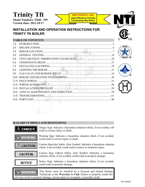
Trinity TftModel Numbers: Tft60 - 399Version Date: 2011-10-17NEW PRODUCT LINEHigh Efficiency FiretubeCondensing Gas BoilerINSTALLATION AND OPERATION INSTRUCTIONS FORTRINITY Tft BOILERTABLE OF CONTENTS1.0 INTRODUCTION................................................................................................................32.0 SPECIFICATIONS ..............................................................................................................63.0 BOILER LOCATION ..........................................................................................................74.0 GENERAL VENTING.......................................................................................................105.0 VENT/AIR-INLET TERMINATION CLEARANCES.....................................................246.0 CONDENSATE DRAIN....................................................................................................277.0 INSTALLING GAS PIPING..............................................................................................298.0 LIGHTING THE BOILER.................................................................................................319.0 GAS VALVE AND BURNER SET-UP ............................................................................3310.0 BOILER AND HEATING SYSTEM PIPING...................................................................3611.0 FIELD WIRING.................................................................................................................5112.0 WIRING SCHEMATICS ...................................................................................................5613.0 INSTALLATION CHECKLIST ........................................................................................5814.0 ANNUAL MAINTENANCE AND INSPECTION ...........................................................5915.0 TROUBLESHOOTING .....................................................................................................6116.0 PARTS LIST ......................................................................................................................80HAZARD SYMBOLS AND DEFINITIONSDanger Sign: Indicates a hazardous situation which, if not avoided, willresult in serious injury or death.Warning Sign: Indicates a hazardous situation which, if not avoided,could result in serious injury or death.Caution Sign plus Safety Alert Symbol: Indicates a hazardous situationwhich, if not avoided, could result in minor or moderate injury.Caution Sign without Safety Alert Symbol: Indicates a hazardoussituation which, if not avoided, could result in property damage.Notice Sign: Indicates a hazardous situation which, if not avoided,could result in property damage.This Boiler must be installed by a licensed and trained HeatingTechnician or the Warranty is Void. Failure to properly install thisunit may result in property damage, serious injury to occupants, or possibly death.NTI # 84535
Trinity │<strong>Install</strong>ation and <strong>Operation</strong> InstructionsTft SeriesRead Before ProceedingIf you do not follow these instructions exactly, a fire or explosion may result causingproperty damage, serious injury or death.FOR YOUR SAFETY, READ BEFORE OPERATING_A) This boiler does not have a pilot. It is equipped with an ignition device which automatically lights theburner. Do not try to light the burner by hand.B) BEFORE OPERATING smell all around the boiler area for gas. Be sure to smell next to the floorbecause some gas is heavier than air and will settle on the floor.WHAT TO DO IF YOU SMELL GAS:• Do not try to light any boiler.• Do not touch any electric switch.• Do not use any phone in your building.• Immediately call your gas supplier from a neighbor's phone. Follow the gas supplier's instructions.• If you cannot reach your gas supplier, call the fire department.C) Use only your hand to turn the gas “shutoff” valve. Never use tools. If the handle will not turn by hand,don't try to repair it, call a qualified service technician. Force or attempted repair may result in a fire orexplosion.D) Do not use this boiler if any part has been under water. Immediately call a qualified service technicianto inspect the boiler and to replace any part of the control system and any gas control which has beenunder water.OPERATING INSTRUCTIONS_1. STOP! Read the safety information above very carefully.2. Set the thermostat to lowest setting. Turn off all electric power to the boiler.3. This boiler does not have a pilot. It is equipped with an ignition device which automatically lights theburner. Do not try to light the burner by hand.4. Turn the manual gas valve to the OFF position. Remove front access panel.5. Wait five (5) minutes to clear out any gas. Then smell for gas, including near the floor. If you smell gas,STOP! Follow “B” in the safety information above. If you don't smell gas, go to the next step.6. Turn the manual gas valve ON. Wait an additional five (5) minutes smelling for gas.7. Replace the front access panel.8. Set thermostat to highest setting. Turn on all electric power to the boiler.9. Ignition sequence is automatic. Combustion will occur after a brief fan purge.10. If ignition does not occur, follow the instructions “To Turn Off Gas To Boiler” and call your servicetechnician or gas supplier.TO TURN OFF GAS TO THE BOILER_1. STOP! Read the safety information above very carefully.2. Turn off all electric power to the boiler.3. Turn the manual gas valve to the OFF position.Crystalline Silica - Certain components confined in the combustion chamber maycontain this potential carcinogen. Improper installation, adjustment, alteration, service ormaintenance can cause property damage, serious injury (exposure to hazardous materials) or death. Refer toSection 14.0 for information on handling instructions and recommended personal protective equipment.<strong>Install</strong>ation and service must be performed by a qualified installer, service agency or the gas supplier (who mustread and follow the supplied instructions before installing, servicing, or removing this boiler. This boilercontains materials that have been identified as carcinogenic, or possibly carcinogenic, to humans).Void Warranty - This Boiler must have water flowing through it whenever the burner ison or it will damage the unit and void the warranty. Failure to follow these instructionsmay result in serious injury or death.2
Tft Series<strong>Install</strong>ation and <strong>Operation</strong> Instructions │Trinity1.0 INTRODUCTIONGeneral <strong>Install</strong>ation RequirementsThe installation of your NTI Trinity Tft gas boiler must conform to the requirements of this manual, your localauthority, and the National Fuel Gas Code ANSI Z223.1 and or CAN/CGA B149 <strong>Install</strong>ation Codes. Whererequired by the Authority, the installation must conform to the standard for “Controls and Safety Devices forAutomatically Fired Boilers ANSI/ASME CSD-1.This document pertains to the correct installation and operation of NTI Trinity boiler model Tft. The instructionsdetailed in this document supersede any and all previous instructions provided by NTI, written or otherwise.Each unit is provided with the following:1. <strong>Install</strong>ation and Operating Instructions,2. Appendix A – Controller and Touchscreen Display Instructions,3. Trinity Users Manual, and4. Natural Gas to LP Conversion Kit** The conversion kit is required to convert the boiler so it will safely operate with Propane Gas.Read and understand this entire document prior to proceeding with the installation of theTrinity Tft. Failure to follow the instructions outlined in this document will result inproperty damage, serious injury or death.User ResponsibilitiesThis boiler must be installed and serviced by a qualified installer or service technician. This boiler must beserviced and inspected annually when operating in normal residential applications. Demanding applications orextreme conditions (i.e. commercial) may require more frequent service and inspection. As the User/Owner ofthis equipment, you are responsible for ensuring the maintenance is performed at the required intervals (seeSection 14 – Annual Maintenance and Inspection).Failure to have the boiler properly serviced and inspected on a regular basis by a qualifiedservice technician may result in property damage, serious injury or death.Failure to keep the Vent and Combustion Air Intake clear of ice, snow, and other debrismay result in property damage, serious injury, or death.<strong>Install</strong>er ResponsibilitiesAs the installing technician it is your responsibility to ensure the installation is performed in accordance with thisinstruction manual as well as any applicable local or National installation codes. It is also your responsibility toinform the User/Owner of their obligation with respect to the above description under “User Responsibilities”.Failure to follow this warning could result in fire, serious injury, or death.Failure to use the appropriate Natural to LP Conversion Kit and Orifice when operatingthe Trinity Tft with Propane will result in extremely dangerous burner operation leadingto property damage, serious injury or death. Refer to section titled ATTENTION: LIQUEFIEDPETROLEUM (LP) PROPANE for applicable conversion kit and LP orifice numbers.3
Trinity │<strong>Install</strong>ation and <strong>Operation</strong> InstructionsTft SeriesATTENTION: LIQUEFIED PETROLEUM (LP) PROPANEThe Trinity Tft is factory set to operate with Natural Gas. BEFORE OPERATING WITH PROPANE, thespecified LP Conversion Kit and Orifice must be installed to convert the boiler so it will operate safely withLP Propane. The correct kit and LP orifice is listed below (Each kit comes with conversion instructions).Liquefied Petroleum (LP) propane gas is heavier than air; therefore, it is imperative that your Trinity Tft boileris not installed in a pit or similar location that will permit heavier than air gas to collect. Local Codes mayrequire boilers fueled with LP gas be provided with an approved means of removing unburned gases from theroom. Check your local codes for this requirement.Natural to LP Propane Conversion Kit_Model Number Kit Number LP OrificeTft60-85 82650-1 415 (4.15mm)Tft110 82650-1 52 (5.2mm)Tft155-250 82650-1 62 (6.2mm)Tft300-399 84471-1 74 (7.4mm)Boiler Vent / Air-Inlet PipingThe Trinity Tft is certified as a “Category IV” boiler, and requires a “Special VentingSystem” designed for pressurized venting. The exhaust gases must be piped directly tothe outdoors using the vent materials and rules outlined in these instructions. Failure to follow these instructionswill result in serious injury or death.IN THE STATE OF MASSACHUSETTS ONLY(a) For all horizontally vented gas fueled equipment installed in every dwelling, building or structure used in whole orin part for residential purposes, including those owned and operated by the Commonwealth and where the side wallexhaust vent termination is less than seven (7) feet above finished grade in the area of the venting, including but notlimited to decks and porches, the following requirements shall be satisfied:1. INSTALLATION OF CARBON MONOXIDE DETECTORS At the time of installation of the side wallhorizontal vented gas fueled equipment, the installing plumber or gas fitter shall observe that a hard wiredcarbon monoxide detector with an alarm and battery back-up is installed on the floor level where the gasequipment is to be installed and on each additional level of the dwelling, building or structure served by theequipment. It shall be the responsibility of the property owner to secure the services of qualified licensedprofessionals for the installation of hard wired carbon monoxide detectors.a. In the event that the side wall horizontally vented gas fueled equipment is installed in a crawl space or anattic, the hard wired carbon monoxide detector with alarm and battery back-up may be installed on the nextadjacent floor level.b. In the event that the requirements of this subdivision can not be met at the time of completion ofinstallation, the owner shall have a period of 30 days to comply with the above requirements; provided,however, that during said 30 day period a battery operated carbon monoxide detector with an alarm shallbe installed.2. APPROVED CARBON MONOXIDE DETECTORS Each carbon monoxide detector as required in accordancewith the above provisions shall comply with NFPA 720 and be ANSI/UL 2034 listed and IAS certified.3. SIGNAGE A metal or plastic identification plate shall be permanently mounted to the exterior of the buildingat a minimum height of eight (8) feet above grade directly in line with the exhaust vent terminal for thehorizontally vented gas fueled heating boiler or equipment. The sign shall read, in print size no less than onehalf(1/2) inch in size, “GAS VENT DIRECTLY BELOW. KEEP CLEAR OF ALL OBSTRUCTIONS”(plate included with boiler).4. INSPECTION The state or local gas inspector of the side wall horizontally vented gas fueled equipment shallnot approve the installation unless, upon inspection, the inspector observes carbon monoxide detectors andsignage installed in accordance with the provisions of 248 CMR 5.08(2)(a)1 through 4.…..Continued on Next Page4
Tft Series<strong>Install</strong>ation and <strong>Operation</strong> Instructions │Trinity…..Continued.(b) EXEMPTIONS: The following equipment is exempt from 248 CMR 5.08(2)(a)1 through 4:1. The equipment listed in Chapter 10 entitled “Equipment Not Required To Be Vented” in the most currentedition of NFPA 54 as adopted by the Board; and2. Product Approved side wall horizontally vented gas fueled equipment installed in a room or structure separatefrom the dwelling, building or structure used in whole or in part for residential purposes.(c) MANUFACTURER REQUIREMENTS – GAS EQUIPMENT VENTING SYSTEM PROVIDED: When themanufacturer of Product Approved side wall horizontally vented gas equipment provides a venting system design orventing system components with the equipment, the instructions provided by the manufacturer for installation of theequipment and the venting system shall include:1. Detailed instructions for installation of the venting system design or the venting system components; and2. A complete parts list for the venting system design or venting system.(d) MANUFACTURER REQUIREMENTS – GAS EQUIPMENT VENTING SYSTEM NOT PROVIDED:When the manufacturer of a Product Approved side wall horizontally vented gas fueled equipment does not providethe parts for venting the flue gases, but identifies “special venting systems”, the following requirements shall besatisfied by the manufacturer:1. The referenced “special venting system” instructions shall be included with the appliance or equipmentinstallation instructions; and2. The “special venting system” shall be Product Approved by the Board, and the instructions for that system shallinclude a parts list and detailed installation instructions.(e) A copy of all installation instructions for all Product Approved side wall horizontally vented gas fueled equipment,all venting instructions, all parts list for venting instructions, and/or all venting design instructions shall remain withthe appliance or equipment at the completion of the installation.5
Trinity │<strong>Install</strong>ation and <strong>Operation</strong> InstructionsTft Series2.0 SPECIFICATIONSTable 2-1 Trinity Tft SpecificationsDESCRIPTION Tft60 Tft85 Tft110 Tft155 Tft175 Tft200 Tft250 Tft300 Tft3991,4CSA Input Modulation[MBH]1,2DOE Heating Capacity[MBH]1,2Net I=B=R Rating[MBH]17-60 17-85 21.6-108 31-155 35-175 40-200 50-250 79.8-299 79.8-39955 77 98 141 159 182 232 272 36347 67 85 123 138 185 202 237 316DOE AFUE 2 [%] - - - - - - - - -Water Connections – NPT[in.]1 1-1/4 1-1/2Gas Connection - NPT, in. 1/2 3/4Vent/Air-inlet Pipe Diameter[in.] 3 2 or 3 3 4Dimensions H x W x D [in.] 33-3/8 x 19-3/4 x 14-1/2 33-3/8 x 19-3/4 x 18-1/2 36-3/8 x 25-1/4 x 20Approx. Boiler Weightwith Water [lbs]110 180 250Approx. Boiler WaterContent [Gallons]3.2 4.9 6.4Electrical Rating120V/1Ph/60Hz/less than12ANotes:1 Listed Input and Output ratings are at minimum vent lengths at an altitude of 0-2000ft. Numbers will be lower withlonger venting and/or altitudes greater then 2000ft.2 Based on rating plate input capacities, using standard test procedures prescribed by the U.S. Department of Energy.AHRI (GAMA) confirmation of ratings pending.3 Trinity Tft requires a special venting system, use only vent materials and methods detailed in these instructions.4 When operating with Propane models Tft60, Tft85 and Tft110 have min/max Input Modulation rates of 17/65, 17.6/88and 22.6/113 MBH respectfully.Wall mounting of unit requires two people to lift the boiler into place. Failure to followthese instructions may result in property damage or personal injury.High Altitude <strong>Operation</strong>The Trinity is designed to operate at its maximum listed capacity in installations located at 0-2000ft above SeaLevel. Since the density of air decreases as elevation increases, maximum specified capacity should be de-ratedfor elevations above 2000 ft [610 m] in accordance with Table 2-2.Table 2-2 De-rate % for High AltitudesElevations 2001 ft [610 m] 3000 ft [914 m] 4000 ft [1219 m] 4500 ft [1372 m] 5000 ft [1524 m]1In Canada2In USAde-rate by 10% de-rate by 10% de-rate by 10% de-rate by 10% de-rate % may vary- de-rate by 4% de-rate by 8% de-rate by 8% de-rate by 12%Notes:1Canada: Altitudes between 2000-4500 ft [610-1372 m], de-rate by 10%. Consult local authorities for de-ratingcapacities for altitudes above 4500 ft [1372 m].2USA: De-rate capacity by 4% for every 1000 ft [305 m] over 2000 ft [610 m].Combustion – At elevations above 2000 feet, the combustion of the boiler must bechecked with a calibrated combustion analyzer to ensure safe and reliable operation. It isthe <strong>Install</strong>ers responsibility to check the combustion and to adjust the combustion in accordance withSection 9.0. Failure to follow these instructions may result in property damage, serious injury, or death.6
Tft Series<strong>Install</strong>ation and <strong>Operation</strong> Instructions │Trinity3.0 BOILER LOCATIONIn all cases, the Trinity Tft must be installed indoors in a dry location where the ambient temperature must bemaintained above freezing and below 100°F [38°C]. All boiler components must be protected from dripping,spraying water, or rain during operation and servicing. Consider the proximity of system piping, gas andelectrical supply, condensate disposal drain, and proximity to vent termination when determining the best boilerlocation.Water or flood damaged components must be replaced immediately with new factoryapprovedcomponents as failure to do so may result in fire, serious injury, or death.Boiler Area Ventilation Air OpeningsIf boiler area clearances are less than the recommended clearances specified in Table 3-1, the boiler area must beventilated (Exception: if the boiler area/room has a volume of 150 ft 3 or greater, ventilation of the boiler room isnot required). Each ventilation air opening must meet the minimum requirements of 1 in 2 per 1000 Btu/hr, butnot less then 100 in 2 . The lower ventilation opening must be located within 6” of the floor while the upperopening must be located 6” from the top of the space.If the "Boiler Area" does not meet the recommended clearances listed in Table 3-1, and ifthe boiler area has a volume less than 150 ft 3 , it is considered a Closet or Alcove. In US /Canada, PVC vent pipe and fittings shall not be used within the closet or alcove; onlyapproved CPVC, Polypropylene or Stainless Steel vent pipe and fittings can be used. See Table 4-4 for a list ofapproved materials. Under all circumstances, the minimum clearances listed in Table 3-1 must be provided.Closet <strong>Install</strong>ationsFor closet installations it is necessary to provide two ventilation air openings as shown in Figure 3-1, eachproviding a minimum area equal to 1 in 2 per 1000 Btu/hr, but not less then 100 in 2 and within 6” of the top andbottom of the closet door. See Table 3-1 for minimum clearances.Alcove <strong>Install</strong>ationsAlcove installations have the same minimum clearances as closet installations, except the front must becompletely open to the room at a distance no greater then 18” [457 mm] from the front of the boiler and theroom is at least three (3) times the size of the alcove. Provided these conditions are met, the boiler requires noextra ventilation air openings to the space. See Table 3-1for minimum clearances.Residential Garage <strong>Install</strong>ationsWhen installed in a residential garage, mount the boiler a minimum of 18” [457 mm] above the floor. Locate orprotect the boiler so it cannot be damaged by a moving vehicle. Check with your local authorities for otherpossible regulations pertaining to the installation of a boiler in a garage.Wall Mounting <strong>Install</strong>ationsThe Tft is provided with integrated wall mounting brackets. Refer to Figure 3-2 for instructions and illustrationson wall mounting.Table 3-1 Minimum Clearances for <strong>Install</strong>ation and ServiceDimensions - inches [mm]Model No. ClearancesFront Top Sides Back Bottom Flue Pipe1Minimum 24 [610] 12 [305] 4 [102] 0 9 [229] 1 [25]Trinity TftRecommended 36 [914] 24 [610] 12 [305] 0 24 [610] 1 [25]Notes:16” if surface is removable allowing a minimum of 24” [610 mm] clearance (i.e. closet installation). See Ventilation AirOpening dimensions in Figure 3-1.Closet/alcove installations in US and Canada require approved CPVC, Polypropylene orStainless Steel vent and air-inlet pipe and fittings (see Table 4-4); PVC is not permitted.Failure to follow these instructions may result in damage or serious injury.7
Trinity │<strong>Install</strong>ation and <strong>Operation</strong> InstructionsTft SeriesFigure 3-1 Closet <strong>Install</strong>ation, Minimum Clearances(Model Tft60-110 Shown)Min. 1” clearance for hotwater and vent pipesTop ventilation openingMax. 6” below ceiling / topTop = 12”Ventilation air opening1in 2 per 1000 Btu/hr,min. 100in 2Removable surface /closet doorVentilation air opening1in 2 per 1000 Btu/hr,min. 100in 2Bottom ventilation openingMax. 6” above floor / bottomBottom = 9”Sides = 4”Front = 6”(if removable)Ventilation Air Openingsare not required if theboiler area meets theRecommended Clearanceslisted in Table 3-1.8
Tft Series<strong>Install</strong>ation and <strong>Operation</strong> Instructions │Trinity While leaving the Upper bracket (A) intact,remove the Wall-mount bracket (B) attachedto the bottom-back of the appliance. Save themounting hardware for Step 4. Secure the Wall-mount bracket (B), removedfrom the bottom of the boiler in Step 1, to asolid wall using field supplied lag screws(anchors when mounting to a concrete wall)that are adequate to support the weight of theappliance (refer to Table 2-1 Specifications).Ensure the Wall-mount bracket is mountedlevel and flush to the wall with mounting holeson the bottom, flange pointed upward andangled away from the wall. Mount the appliance to the wall by aligning theUpper bracket (A) with the Wall-mountbracket (B). Slide the Upper bracket downover the wall mount bracket until it hooks. Once the appliance is resting securely on theUpper bracket, secure the Bottom bracket (C)to the underside of the appliance using themounting hardware removed in Step 1; then,anchor the bottom bracket to the wall as shownusing field supplied hardware.Figure 3-2 Wall Mounting InstructionsUpper bracket (A)Wall-mountbracket (B)Failure to follow instructions mayresult in fire, serious injury, or death.This unit requires two people to lift itor damage and injury may result. Wall BoilerWall-mountbracket (B)(A)Ensure bracket(A) fully insertsinto bracket (B)(B)Bottom bracket (C) shippedwith boiler package9
Trinity │<strong>Install</strong>ation and <strong>Operation</strong> InstructionsTft Series4.0 GENERAL VENTINGThe Trinity Tft is certified as a “Category IV” boiler requiring a “Special Venting System” designed forpressurized venting. The Exhaust Vent must be piped to the outdoors, using the vent materials and rules outlinedin this section. Under no conditions may this unit vent gases into a masonry chimney, unless it is vacant, andutilizes the approved venting material and rules described in this section.Vent and Air-inlet are to be piped separately. The Trinity Tft cannot share a common ventor air-inlet with multiple boilers. Failure to comply will result in serious injury or death.Direct Vent <strong>Install</strong>ation (Best Practice)When installed as a Direct Vent boiler the combustion air-inlet must also be piped directly to the outdoors usingthe methods described in this section and in accordance with the National Fuel Gas Code, ANSI Z223.1 (U.S.) orCSA B149.1 (Canada) and local requirements.<strong>Install</strong>ation Using Indoor Combustion AirWhen the installation uses Indoor Combustion Air (i.e. piping is not directly connecting the appliance air-inletfitting to the outdoors), the combustion air-inlet is drawn from Indoors or Outdoors via the appliance area usingthe methods described in this section and in accordance with the National Fuel Gas Code, ANSI Z223.1 (U.S.) orCSA B149.1 (Canada) and local requirements.The boiler shall be located so as not to interfere with proper circulation of combustion,ventilation, and dilution air.Make up air requirements for the operation of exhaust fans, kitchen ventilation systems,clothes dryers, and fireplaces shall be considered in determining the adequacy of a spaceto provide combustion air requirements. Failure to ensure adequate make up air to allappliances may result in personal injury or death.Indoor Combustion Air - Opening Size and Location: The methods detailed below for determining OpeningSize and Location for accessing indoor combustion air, shall be used when the air infiltration rate is adequate, i.e.greater than 0.4 ACH (air changes per hour) and when the boiler area and communicating spaces have aminimum volume of 50 cubic ft per 1000 Btu/hr. If the air infiltration rate is known to be less that 0.4 ACH,refer to the National Fuel Gas Code for further guidance.1. Combined spaces on the same story – Each opening shall have a minimum free area of 1 in. 2 /1000 Btu/hrof the total input rating of all appliances in the space, but not less than 100 in. 2 . One opening shallcommence within 12 in. of the top, and one opening shall commence within 12 in. of the bottom, of theenclosure, see Figure 4-1a. The minimum dimension of air openings shall be not less than 3in.2. Combined spaces in different stories – The volumes of spaces in different stories shall be considered ascommunicating spaces where such spaces are connected by one or more openings in doors or floors having atotal minimum free area of 2 in. 2 /1000 Btu/hr of total input rating of all appliances.Outdoor Combustion Air – Opening Size and Location: Outdoor combustion air shall be provided throughopening(s) to the outdoors in accordance with the methods detailed below. The minimum dimension of airopenings shall not be less than 3in.1. Two Permanent Openings Method – Two permanent openings, one commencing within 12in. of the top,and one commencing within 12in. of the bottom of the enclosure, shall be provided. The openings shallcommunicate directly, or by ducts, with the outdoors or spaces that freely communicate with the outdoors, asfollows:a. Where communicating with the outdoors or where communicating to the outdoors through vertical ducts,each opening shall have a minimum free area of 1 in. 2 /4000 Btu/hr of total input rating of all appliancesin the enclosure; see Figures 4-1b and 4-1c.b. Where communicating with the outdoors through horizontal ducts, each opening shall have a minimumfree area of 1 in. 2 /2000 Btu/hr of total input rating of all appliances in the enclosure; see Figure 4-1d.10
Tft Series<strong>Install</strong>ation and <strong>Operation</strong> Instructions │Trinity2. One Permanent Opening Method – One permanent opening, commencing within 12 in. of the top of theenclosure, shall be provided. The appliance shall have clearances of at least 1 in. from the sides and backand 6 in. from the front of the appliance. The opening shall directly communicate with the outdoors or shallcommunicate through a vertical or horizontal duct to the outdoors or spaces that freely communicate with theoutdoors (see Figure 4-1e) and shall have a minimum free area of the following:a. 1 in. 2 /3000 Btu/hr of the total input rating of all appliances located in the enclosure, andb. Not less than the sum of the areas of all appliance vent connectors in the space.3. Combination Indoor and Outdoor Combustion Air – The use of a combination of indoor and outdoorcombustion air shall be in accordance with the following:a. Indoor Openings – where used, openings connecting the interior spaces shall comply with “IndoorCombustion Air – Opening and Size and Location” described above.b. Outdoor Openings – Outdoor opening(s) shall be located in accordance with “Outdoor Combustion Air– Opening Size and Location” described above.c. Outdoor Opening(s) Size – The outdoor opening(s) size shall be calculated in accordance with thefollowing:i. The ratio of interior spaces shall be the available volume of all communicating spaces divided by therequired volume (i.e. 50 cubic ft per 1000 Btu/hr if 0.4 ACH or greater).ii. The outdoor size reduction factor shall be 1 minus the ratio of interior spaces.iii. The minimum size of outdoor opening(s) shall be the full size of outdoor opening(s) calculated inaccordance with “Outdoor Combustion Air – Opening Size and Location” described above, multipliedby the reduction factor. The minimum dimension of air openings shall not be less than 3 in.Figure 4-1(a) Indoor Air Figure 4-1(b) Two Vertical Ducts Figure 4-1(c) Two Vertical DuctExhaust VentExhaust VentVentilation Louvers(each end of attic)Exhaust VentVentilation Louvers(each end of attic)Opening (within1ft of ceiling)OpeningOpeningOpening (within1ft of floor)OpeningVentilated & unheatedcrawl spaceOpening (ductextended to within1ft of floor)Figure 4-1(d) Two Horizontal DuctsFigure 4-1(e) One Duct OptionsExhaust VentExhaust VentVentilation Louvers(each end of attic)Opening Option AOpening (within1ft of ceiling)Opening (within1ft of floor)Opening Option B(within 1ft of ceiling)11
Trinity │<strong>Install</strong>ation and <strong>Operation</strong> InstructionsTft SeriesCombustion Air-inlet ContaminationBe careful not to locate the air-inlet termination in an area where contaminants can be drawn in and used forcombustion. Combustion air containing dust, debris or air-borne contaminants will drastically increase therequired maintenance and may cause a corrosive reaction in the Heat Exchanger which could result in prematurefailure, fire, serious injury, or death. See Table 4-1 for a list of areas to avoid when terminating air-inlet piping:Table 4-1 Corrosive <strong>Products</strong> and Contaminant Sources<strong>Products</strong> to AvoidAntistatic fabric softeners, bleaches, detergents, cleanersPerchloroethylene (PCE), hydrocarbon based cleanersChemical fertilizer, herbicides/pesticides, dust, methane gasPaint or varnish removers, cements or glues, sawdustWater chlorination chemicals (chloride, fluoride)Solvents, cutting oils, fiberglass, cleaning solventsRefrigerant charge with CFC or HCFCPermanent wave solutionsFixer, hydrochloric acid (muriatic acid), bromide, iodineCement powder, crack fill dust, cellulose, fiber based insulationContaminated Sources to AvoidLaundry facilitiesDry cleaning facilitiesFarms or areas with livestock and manureWood working or furniture refinishing shopsSwimming pools, hot tubsAuto body or metal working shopsRefrigerant repair shopsBeauty shopsPhoto labs, chemical / plastics processing plantsConcrete plant or construction siteDo not store or use gasoline or other flammable vapors and liquids in the vicinity of thisor any other boiler. Failure to follow instructions may result in serious injury or death.It is BEST PRACTICE to pipe the combustion air-inlet directly to the outdoors (DirectVent installation) to avoid contamination often contained in indoor air.Flammable Solvents and Plastic PipingDue to the extremely flammable characteristics of most glues, cements, solvents and primers used in the processof joining plastic vent and air-inlet pipe, explosive solvent vapors must be evacuated from the vent and air-inletprior to start-up. Avoid using excess cement or primer that may lead to pooling inside the pipe assembly. Freshlyassembled piping assembly should be allowed to cure for a minimum of 8 hours before applying power to the gasfired boiler. Refer to Mandatory Pre-commissioning Procedure for Plastic Venting in this section.Flammable Cements and Primers – It is the installers’ responsibility to familiarizethemselves with the hazards associated with explosive solvents and to take all precautionsto reduce these risks. Failure to follow these instructions can cause explosions, property damage, injury or death.Near Boiler Vent/Air-inlet PipingEach Trinity Tft is equipped with a short piece of approved CPVC vent pipe which is to be used when ventingwith PVC. Insert one end into the boiler flue outlet adapter and cement the other to the field venting (see Table 4-4 for approved venting material). The CPVC vent pipe should extend fully into the boiler flue outlet adapter (seeTable 4-2). DO NOT insert PVC pipe directly into the flue outlet connection as it can deform from the clampingforce of the gear clamp. Ensure that the venting system does not apply a load or strain on the boiler flue outletadapter. The manufacturer recommends using two elbows to create a “swing joint” to reduce potential strain onvent piping and cemented joints. See Figures 4-2 through 4-4 for illustrations.Gasket Seating - Improper seating can cause leakage and eventual failure of the sealinggasket. Ensure the vent pipe is adequately beveled prior to inserting into the boiler flueadapter. Failure to follow these instructions may result in serious injury or death.12
Tft Series<strong>Install</strong>ation and <strong>Operation</strong> Instructions │TrinityFigure 4-2(a) Trinity Tft60-110 & 300-399 Figure 4-2(b) Trinity Tft60-110 & 300-399Near Boiler Venting (CPVC)Near Boiler Venting (PVC)Air-inletPipe *Swing Jointto attain slope inhorizontal runsAir-inletPipe *Swing Jointto attain slope inhorizontal runsAir InletAdapter(factorysupplied)PVC Exhaust Vent -(check local codesand Table 4-3)Air InletAdapter(factorysupplied)CPVC ExhaustVentFlue OutletAdapter (factorysupplied)PVC CouplingCPVC TransitionPipe - minimum 5”long (factory supplied)Flue OutletAdapter (factorysupplied)Mandatory Vent PipeTransition PipeSee Table 4-2.Air-inlet Pipe *Figure 4-2(c) Trinity Tft155-250Near Boiler Venting (CPVC)Air-inletPipe *Figure 4-2(d) Trinity Tft155-250Near Boiler Venting (PVC)Swing Joint to attainslope in horizontal runsAir Inlet Adapter(factory supplied)Swing Jointto attain slope inhorizontal runsAir InletAdapter(factorysupplied)PVC Exhaust Vent -(check local codesand Table 4-3)CPVC ExhaustVentFlue OutletAdapter (factorysupplied)PVC CouplingCPVC TransitionPipe - minimum 5”long (factory supplied)Flue OutletAdapter (factorysupplied)Mandatory Vent PipeTransition PipeSee Table 4-2.Air-inlet - check with applicable local codes for acceptable pipe material.Exhaust venting must be supported to reduce strain on piping joints. Failure to followthese instructions may result in result in damage, serious injury or death.In Canada, the first 3 ft (915 mm) of vent piping must be readily accessible for inspection.13
Trinity │<strong>Install</strong>ation and <strong>Operation</strong> InstructionsTft SeriesFigure 4-2(e) Trinity Tft60-110 & 300-399 Figure 4-2(f) Trinity Tft60-110 & 300-399Near Boiler Venting (Stainless Steel)Near Boiler Venting (Polypropylene)SS Air-inlet PipePPS Elboww/ offset angle toaccount for slopePPS Air-inlet PipeSwing Jointto attain slope inhorizontal runsSS ExhaustVentSS Appliance Adapter(see Table 4-3)Air Inlet Adapter(factory supplied)PPS Exhaust VentPPS Appliance Adapter(see Table 4-3)Air-inlet Adapter(factory supplied)Flue OutletAdapter (factorysupplied)Flue Outlet Adapter(factory supplied)Figure 4-2(g) Trinity Tft155-250Near Boiler Venting (Stainless Steel)Figure 4-2(h) Trinity Tft155-250Near Boiler Venting (Polypropylene)SS Air-inlet PipePPS Air-inlet PipePPS Elboww/offset angle toaccount for slopeFasNSeal ApplianceAdapter (see Table 4-3)Swing Jointto attain slope inhorizontal runsPPS Exhaust VentAir Inlet Adapter(factory supplied)SS ExhaustVentAir Inlet Adapter(factory supplied)PPS Appliance Adapter(see Table 4-3)Flue OutletAdapter (factorysupplied)Flue Outlet Adapter(factory supplied)Air-Inlet - check with applicable local codes for acceptable pipe material.Exhaust venting must be supported to reduce strain on piping joints. Failure to followthese instructions may result in result in damage, serious injury or death.In Canada, the first 3 ft (915 mm) of vent piping must be readily accessible for inspection.14
Tft Series<strong>Install</strong>ation and <strong>Operation</strong> Instructions │TrinityTable 4-2 CPVC Vent Pipe Transition Piece (used when venting with PVC)Model No. Vent Pipe Size CPVC Transition Vent Pipe Length Full Insertion DepthTft60-110 3” Minimum 5” [127 mm] 2-7/8” [73 mm]Tft155-250 3” Minimum 5” [127 mm] 2-5/8” [67 mm]Tft300-399 4” Minimum 5” [127 mm] 2-5/8” [67 mm]Table 4-3 Appliance Adapters for Polypropylene and Stainless Steel VentingModel No. Vent Material Venting Brand Adapter Part No. 1,2Tft60-250Polypropylene DuraVent – PolyPro 300150Stainless Steel DuraVent – FasNSeal 300715Polypropylene DuraVent – PolyPro 300151Tft300-399Stainless Steel DuraVent – FasNSeal 303631Notes:1Listed appliance adapters are only approved for DuraVent PolyPro or FasNSeal venting; they are not for use with ventingof any other brand.2PolyPro and FasNSeal appliance adapters are available from DuraVent (1-800-835-4429 or www.duravent.com).Vent/Air-inlet Pipe MaterialTable 4-4 Acceptable Vent and Air-Inlet Pipe MaterialVenting System StandardsItems 1 Materials 2, 3 United States Canada 4Vent Pipingand FittingsPVC - DWVPVC Schedule 40CPVC Schedule 40Stainless Steel (SS)Polypropylene (PP) -ANSI/ASTM D2265ANSI/ASTM D1785ANSI/ASTM F441UL-1738All venting material inCanada must beULC S636 approved.See Note 4 below forappropriate temperatureapplications.All Vent and Air-Inletmaterials installed on gasfired appliances in CAN/USmust meet the Standardslisted in this Table. Failureto comply could result infire, serious injury or death.PVCANSI/ASTM D2564Pipe CementCPVCANSI/ASTM F493Primers PVC / CPVC ANSI/ASTM F656Notes:1Refer to Table 4-5 for Allowable Vent and Air-Inlet Pipe Sizes and Lengths.2PVC venting (exhaust and air-inlet) is not permitted within the Closet/alcove of a Closet/alcove installation.3The Air-inlet does not require high temperature pipe material. Check applicable local codes for acceptable materials.4ULC S636 PVC is approved for flue gas temperatures up to 149 o F (65 o C) and must only be used for low temperatureapplications. High temperature applications requiring appliance supply water temperatures greater than 140 o F (60 o C)must use ULC S636 CPVC, PP or SS.Mandatory Pre-commissioning Procedure for Plastic Venting (PVC or CPVC)Do not apply power to the boiler prior to Step 4 in the Mandatory Pre-commissioningProcedure for Plastic Venting.1) Working with the power turned off to the boiler, completely install the vent and air intake system, securelycementing joints together. If possible, allow primers/cements to cure for 8 hours before firing the burner. Ifcuring time is less than 8 hours, proceed with Steps 2 through 6.2) Maintain the boiler gas supply shut-off valve in the off position.3) Remove the cable from the Spark Ignition Transformer.Spark Ignition Circuit - Maintain a safe distance (2 inches minimum) from the sparkignition circuit to avoid injury from electrical shock.4) Turn power on to the boiler and apply a heat demand.5) Allow for 3 complete trials for ignition, consisting of pre and post purge of the combustion blower, until anignition lockout occurs. Repeat the process two more times (i.e. 9 complete ignition sequences in total).6) Turn power off and reconnect the cable to the Spark Ignition Transformer.15
Trinity │<strong>Install</strong>ation and <strong>Operation</strong> InstructionsTft SeriesVent/Air-inlet Pipe Length DeterminationUse Table 4-5 to determine the maximum pipe length that can be used. The table calculates 90º elbows, and 45ºelbows at 5 equivalent feet each.Example: When using 3” pipe, a Tft60-110 can be installed with 150 equivalent feet of air-inlet piping and 150equivalent feet of exhaust-vent piping. See Table 4-5 for more details.When operating on Propane, models Tft60-110 require a minimum vent/air-inlet length of6’ and 11’ for 2” and 3” venting respectfully.Table 4-5 Allowable Vent and Air-inlet Pipe Size and LengthsPipeLengthNumber of Elbows (90’s or 45’s) and Equivalent FeetModel No.GasSize(ft) 1 2 3 4 5 6 7 8 9Tft60-110 NG 100 95 90 85 80 75 70 65 60 55Tft60-85 2” 1 35 30 25 20 15 10 5 - - -LPTft11025 20 15 10 5 - - - - -Tft60-110 150 145 140 135 130 125 120 115 110 1053”Tft155-250NG/LP 100 95 90 85 80 75 70 65 60 55Tft300-399 4”Note:1 See WARNING below.100 95 90 85 80 75 70 65 60 55PVC Exhaust Venting – When using 2” PVC venting with models Tft60-110, the firstseven (7) equivalent feet of exhaust venting must be approved 2” CPVC or 3” PVC; seeexceptions in Table 4-4 and Figures 4-2b and 4-2d.16
Tft Series<strong>Install</strong>ation and <strong>Operation</strong> Instructions │TrinityTermination Options – Direct Vent <strong>Install</strong>ationThe venting system of the Tft may be terminated using field supplied piping to construct a “Two-Pipe”termination, see Figures 4-3a, 4-4a, 4-4d, 4-5a, 4-6a and 4-6d; alternatively the venting may be terminated usinga factory kit selected from Table 4-6. The “IPEX Low Profile” kit (see Figures 4-3b and 4-5c) and “M&GDuraVent Concentric (Wall)” kit (see Figures 4-3d and 4-5d) can be used for Sidewall terminations, while the“M&G DuraVent Concentric (Roof)” kit (see Figures 4-4c and 4-6c) can be used for Rooftop terminations; the“IPEX Concentric” kit (see Figures 4-3c, 4-4b, 4-5b and 4-6b) can be used for either Sidewall or Rooftopterminations.Venting Options - Due to potential moisture loading (build-up) along the exterior wall,sidewall venting may not be the preferred venting option (see Figures 4-4 and 4-6).Optional Termination Kits – Direct Vent <strong>Install</strong>ationKits certified with the Trinity Tft are listed in Table 4-6 and available from IPEX, DuraVent and/or NTI. Formore information on System 636 Vent Kits or wholesaler locations contact IPEX directly USA: 1-800-463-9572or www.IPEXamerica.com │ CAN: 1-866-473-9462 or www.ipexinc.com. For more information on PolyProVent Kits or wholesaler locations contact DuraVent directly 1-800-835-4429 or www.duravent.com.Table 4-6 Optional Vent Termination KitsVentDescriptionVent Material NTI P/N Supplier P/N Boiler ModelsSize2” 196984 Tft60-110IPEX Low Profile3” 84357 196985 Tft60-250(Flush Mount) 7 PVC/CPVC 74”84358 196986 Tft300-399Vent OptionRoof Walľ2” 196005 Tft60-110PVCIPEX Concentric82666 1960063”Tft60-250(Wall/Roof) 5,6,7 CPVC 1970094” PVC 84355 196021 Tft300-399̌̌DuraVent - PolyProConcentric (Wall)DuraVent - PolyProConcentric (Roof)2” 2PPS-HK Tft60-1103” 3PPS-HK Tft60-2504” 4PPS-HK Tft300-399PVC/CPVC/PP2” 2PPS-VK Tft60-1103” 3PPS-VK Tft60-2504”4PPS-VKTft300-399Notes:1 Instructions included with termination kits contain detailed assembly and installation instructions.2 All factory termination kits are ULC S636 approved.Clearance requirements in this manual supersede those of the instructions included with the vent terminal.4 Piping MUST be secured to the vent terminal during installation.5 IPEX Concentric Terminal MUST be cemented together and to the vent pipes during installation.6 Vent Screens provided with boiler may be used with the IPEX Concentric Vent Kits; otherwise use IPEX vent screens(2” vent screen P/N 196050; 3" vent screen P/N 196051; 4" vent screen P/N 196052 – each sold separately).7 IPEX Low Profile and Concentric kits (excluding p/n 197009) are constructed out of ULC S636 approved PVC; checkwith your local authority for the acceptance of PVC as a venting material prior to use.̌̌17
Trinity │<strong>Install</strong>ation and <strong>Operation</strong> InstructionsSidewall Venting Options – Direct Vent <strong>Install</strong>ationFigure 4-3(a)Two-pipe Termination (Sidewall)Figure 4-3(b)IPEX Low Profile Termination (Sidewall)Tft SeriesLocation of exhaust and air-inletconnections vary betweenmodels, see Figure 4-2.(model Tft60-110 shown)Location of exhaust and air-inletconnections vary betweenmodels, see Figure 4-2.(model Tft60-110 shown)InletExhaustExhaustInletFigure 4-3(c)IPEX Concentric Termination (Sidewall)Figure 4-3(d)DuraVent Concentric Termination (Sidewall)Location of exhaust and air-inletconnections vary betweenmodels, see Figure 4-2.(model Tft60-110 shown)Location of exhaust and air-inletconnections vary betweenmodels, see Figure 4-2.(model Tft60-110 shown)InletExhaustExhaustInlet18
Tft SeriesRoof Venting Options – Direct Vent <strong>Install</strong>ationFigure 4-4(a)Two-pipe Termination (Roof)<strong>Install</strong>ation and <strong>Operation</strong> Instructions │TrinityFigure 4-4(b)IPEX Concentric Termination (Roof)Location of exhaust and air-inletconnections vary betweenmodels, see Figure 4-2.(model Tft60-110 shown)Location of exhaust and air-inletconnections vary betweenmodels, see Figure 4-2.(model Tft60-110 shown)InletInletExhaustExhaustFigure 4-4(c)DuraVent Concentric Termination (Roof)Figure 4-4(d)Two-pipe Termination (Roof-exhaust / Sidewall-inlet)Location of exhaust and air-inletconnections vary betweenmodels, see Figure 4-2.(model Tft60-110 shown)Location of exhaust and air-inletconnections vary betweenmodels, see Figure 4-2.(model Tft60-110 shown)ExhaustInletExhaustInlet19
Trinity │<strong>Install</strong>ation and <strong>Operation</strong> InstructionsSidewall Termination Details – Direct Vent <strong>Install</strong>ationFigure 4-5(a)Two-Pipe Termination (Sidewall)Figure 4-5(b)IPEX Concentric Termination (Sidewall)Tft SeriesExhaustVerticalMin. 18”Horizontal4-12” or greaterthan 36”ExhaustAir-inletRefer to documentation included with termination kit forcomplete installation instructions.ExhaustAir-inletAir-inletVent ScreenGas Vent Directly BelowKeep Free of ObstructionsAir-inlet aroundperimeter (1-2”from wall)Exhaust throughcenterMin. 12”above gradeor snow levelVent pipe piece toretain vent screenMin. 12”above gradeor snow levelVent ScreenVent pipe piece toretain vent screenFigure 4-5(c)IPEX Low Profile TerminationFigure 4-5(d)DuraVent PolyPro Wall TerminationRefer to documentation included with termination kit forcomplete installation instructions.Refer to documentation included with termination kit forcomplete installation instructions.ExhaustAir-inletExhaustAir-inlet aroundperimeterAir-inletExhaustGas Vent Directly BelowKeep Free of ObstructionsAir-inlet bottomExhaust centerMin. 12”above gradeor snow levelMin. 12”above gradeor snow level20
•Tft Series<strong>Install</strong>ation and <strong>Operation</strong> Instructions │TrinityRoof Termination Details – Direct Vent <strong>Install</strong>ationFigure 4-6(a)Two-Pipe Termination (Roof)Figure 4-6(b)IPEX Concentric Termination (Roof)ExhaustVent ScreenVent pipe piece toretain vent screenRefer to documentation included with termination kit forcomplete installation instructions.Vent pipe piece toretain vent screenVerticalMin. 18”Air-inletExhaust centerVent ScreenMin. 12”above gradeor snow levelAir-inlet aroundperimeterMin. 12”above gradeor snow levelFlashingHorizontal4-12” or greaterthan 36”FlashingFigure 4-6(c)DuraVent PolyPro Roof TerminationFigure 4-6(d)Exhaust only Roof TerminationRefer to documentation included with termination kit forcomplete installation instructions.Figure illustrates two options for exhaust termination only;neither vent pipe illustrated is for combustion air-inlet.Vent pipe piece toretain vent screenExhaustOption 1ExhaustVent ScreenAir-inletMin. 12”above gradeor snow levelMin. 12”above gradeor snow levelExhaustOption 2FlashingFlashing21
Trinity │<strong>Install</strong>ation and <strong>Operation</strong> InstructionsTft SeriesVenting Rules and Guidelines1. Prevailing Winds: Ensure the vent is located where it will not be exposed to normal prevailing winds.2. Combustion Air-inlet Contamination: Air for combustion must be drawn from an area free of dust andcontaminants. Combustion air containing chemicals such as chloride, fluoride, bromine or iodine or dustand debris will cause corrosion damage of the heat exchanger voiding your NTI warranty. Refer to Table 4-1 for a list of corrosive products and contaminants sources to avoid.3. Vertical Separation: The exhaust must be a minimum of 18” [457 mm] above the air inlet, and the air inletmust always be a minimum of 12” [305 mm] plus snow allowance above any surface that will support snow.(Two feet plus snow allowance is highly recommended). Consult your weather office for the maximumtypical snowfall for your region.Example: New Brunswick Canada - typical maximum snowfall is 19”, thus the inlet must be (12”+19”) =31” above grade and exhaust must be (31”+18”) = 49” above grade.4. Horizontal Separation: The horizontal distance between the inlet and exhaust must be a minimum of 4”[102 mm] center to center.5. Wall Flashing: Under normal operating conditions this boiler will produce a plume of white gases, andshould be taken into consideration when selecting an adequate location. A 36” [915 mm] diameter stainless,plastic, or vinyl shield can be used to flash the exterior of the residence.6. Flue Gas Hazard: Position the vent termination where vapors cannot make accidental contact with peopleand pets or damage nearby shrubs and plants.7. Elbow Extensions: Elbows on outside of wall must be no more than ½” [13 mm] away from the wall.8. Vent Sloping: All indoor exhaust piping must be on a slope back to the boiler a minimum of ¼” per linearfoot of vent [6.25 mm per linear 305 mm]. For applications where excessive condensation is possible ½” perlinear foot [13 mm per linear 305 mm] is recommended.9. Vent Supports: Where required Vent and Air-inlet piping shall be secured to the wall for more rigidity. Allinterior vent pipe shall be supported a minimum of every 36” [915 mm].10. Roof Exhaust: In all roof applications the discharge must point away from the pitch of the roof.11. Roof Flashing: <strong>Install</strong> adequate flashing where the pipe enters the roof, to prevent water leakage.12. Rain Cap: <strong>Install</strong> and seal a rain cap over existing chimney openings, in vacant chimney applications.13. Venting Below Grade: For installations that exit the wall below grade refer to Figure 4-7.14. Vent Screens: <strong>Install</strong> factory supplied vent screens on the outside of the last elbow for both the inlet andexhaust vent terminal elbows. <strong>Install</strong> the screen into the female opening of the elbow, and then cut a smallpiece of pipe to sandwich the screen into the elbow. NOTE: ensure the small piece of pipe cut, does notextend past the end of the elbow. Two screens are provided in the package. See Figures 4-5 and 4-6.15. Condensate Hazard: Do not locate vent over public walkways, driveways or parking lots. Condensatecould drip and freeze resulting in a slip hazard or damage to vehicles and machinery.16. Warning Plate: For Sidewall Venting, install the warning plate “Gas Vent Directly Below”, directly above(within 4 ft [1.22 m] vertically) the location of the air-inlet pipe, so it is visible from at least 8 ft [2.4 m]away. See Figure 4-5.17. Wall Thickness: Direct vent terminations are designed to work with any standard wall thickness.<strong>Install</strong>ation guidelines for min/max wall thickness are as follows: Min.= 1” [25mm], Max.= 60” [1.52 m].18. Venting Options: Due to potential moisture loading (build-up) along the exterior wall, sidewall ventingmay not be the preferred venting option. Refer to Figures 4-4 and 4-6 for roof top venting options.22
Tft Series<strong>Install</strong>ation and <strong>Operation</strong> Instructions │TrinityFigure 4-7 Venting Below GradeFor installations that exit the wall below grade:1. Excavate site to a point below where the pipesare to exit as shown.2. Ensure the wall is fully sealed where the pipespenetrate.3. The Vent/Air-inlet piping MUST be secured tothe side of the building above grade, as shown,to provide rigidity.4. Optional mounting bracket PN. 82075 forsecuring the exhaust pipes (only applicable for3” PVC/CPVC venting).5. Ensure that the Vent/Air-inlet clearances aremaintained, see Section 5.0 for details.Air-inletExhaustWall BracketsFigure 4-8 Outdoor Horizontal VentingVent piping outside the Building is permitted underthe following conditions:1. The maximum length outside the building is 20feet [6.1 m]. Note that outdoor length must beincluded in the overall vent length calculation.2. All normal termination clearances are maintained.3. All exterior exhaust vent pipes are insulated with½” [13 mm] thick, Closed Cell FoamedPolyolefin Tubing i.e., “Tundra Seal Plus” orequivalent.4. The pipe is supported every 24” [610 mm].5. The exhaust and inlet are sloped back to the boiler½” elevation for every linear foot [13 mm forevery linear 305 mm].Gas Vent Directly BelowKeep Free of ObstructionsAir-InletExhaustVent12” [305 mm] plus snowallowance above gradeSupports every24” [610 mm]Maximum of 20 ft[6.1 m] is permittedfor piping outside abuilding.Figure 4-9 Existing Chimney Chase WayIt is permissible to use an existing chimney as a chaseway to run the Vent/Air-inlet piping as long as:Exhaust Vent1. The chimney is not being used by any otherboiler.2. Flue gases don’t enter the vacant chimney.3. Only Trinity certified venting materials are used,see Section 4.0.4. Vent lengths are within the maximums specified.5. The top of the chimney is capped and theVent/Air-inlet pipes are flashed to preventleakage into the vacant chimney.ChimneyCapExistingChimney(used as achase way)Air-InletExhaust Vent Min.18” [457 mm]above air-inletAir-InletMin. 12” [305 mm]above roof andsnow level23
Trinity │<strong>Install</strong>ation and <strong>Operation</strong> InstructionsTft Series5.0 VENT/AIR-INLET TERMINATION CLEARANCESThe quick reference table below is to be read in conjunction with the numbered notes asindicated, Figures 5-1 and 5-2, and the Venting Rules and Guidelines in Section 4.0. Theinstructions detailed in this section are a combination of Trinity Tft specific and National Gas Code restrictions.Compliance alone doesn’t insure a satisfactory installation as good common sense must also be applied. Failureto follow these instructions may result in fire, property damage, serious injury or death.Table 5-1 Termination Clearances Quick Reference Table (See Figures 5-1 and 5-2)Clearances to Air-Inlet TerminationCanada 1 USA 2Min. Distance Min. DistanceA Above grade/roofline and snow level 8 12 in. 305 mm 12 in. 305 mmB Above roof line - Concentric Vent 6, 11, 13 24 in. 610 mm 24 in. 610 mmC To exhaust vent from any other boiler 36 in. 915 mm 12 in. 305 mmClearances to Exhaust Vent Termination Min. Distance Min. DistanceD Minimum vertical separation above air inlet 9 18 in. 457 mm 18 in. 457 mmE Minimum horizontal separation from air inlet 3 4 in. 102 mm 4 in. 102 mmF Window, door or building opening 36 in. 915 mm 12 in. 305 mmG To combustion air inlet from any other boiler 36 in. 915 mm 12 in. 305 mmH Non-mechanical air supply inlet to building 36 in. 915 mm 12 in. 305 mmI Mechanical air supply inlet to building 4 6 ft. 1.83 m 3 ft. 915 mmJ Soffit, overhang, eave or parapet 24 in. 610 mm 24 in. 610 mmK Soffit vent or vent opening in an overhang, eave or parapet 6 ft. 1.83 m 6 ft. 1.83 mL Outside corner 10 - - - -M Inside corner of an L-shaped structure (including walls and fences) 36 in. 915 mm 36 in. 915 mmN Electric meters, gas meters, regulators and relief equipment 6 ft. 1.83 m 4 ft. 1.22 mP Each side of center line above or below meters, regulators and relief devices 5 36 in. 915 mm 36 in. 915 mmQ Above a paved sidewalk, driveway, or parking lot on public property if adjacent 12 7 ft. 2.13 m 7 ft. 2.13 mR Above a sidewalk, driveway, or parking lot on public property X X X XS Above a sidewalk, driveway on private property between / serving both dwellings X X X XT Under a concrete veranda, porch, deck, or balcony 7 24 in. 610 mm 24 in. 610 mmU Above, under or near exterior stairs X X X XV Into a canopy or carport X X X XNotes:1 - Canadian installations must comply with the current CSA B149.1 Natural Gas and Propane <strong>Install</strong>ation Code and localbuilding codes.2 - US installations must comply with current ANSI Z223.1/ NFPA 54 National Fuel Gas Code and local building codes.3 - Horizontal separation center-to-center (c.c.) 4”-12” (102-305 mm).4 - For US installations, an exhaust vent may be 3 ft above a mechanical air supply inlet if within 10 ft. [3 m] horizontally.5 - Horizontal clearance must be observed up to a height of 15 ft. [4.6 m] above/below the meter, regulator, or relief devices.6 - Concentric Vent must protrude from the roof precisely 24” [610 mm] measuring from the terminal end-cap vanes.7 - Permitted if veranda, porch, deck, or balcony is made of concrete and a minimum of two sides are fully open beneath.8 - 24” is the recommended snow level allowance above grade/roofline or any surface that will support snow, debris, or ice(i.e. for roof venting clearances - roofline and snow level). If living in a snowfall region, consult your local weatheroffice for the maximum typical snowfall for your area.9 - Note that the vent must maintain a minimum vertical distance above the air-inlet. Example: Vent height = 18” (457mm) above air inlet + 12” (305 mm) for air inlet above grade/roof line and snow level = 30” (762 mm) above grade andsnow level.10 - Clearances to an outside corner to be in accordance with local installation codes.11 - In Canada, concentric vent materials are subject to approval by local inspectors. See Termination Kits in Section 4.0.12 - Above public walkways, driveways or parking lots if adjacent to it and condensate cannot drip, freeze, or create a hazard.13 - Contact the manufacturer for special exemptions relating to multiple boiler installations using concentric vents._X - Not permitted by National gas code(s) and/or recommended by boiler manufacturer.24
Tft Series<strong>Install</strong>ation and <strong>Operation</strong> Instructions │TrinityFigure 5-1 Termination Clearance Quick Reference Diagram (See Table 5-1)Illustrations of Termination ClearancesFigure 5-2 Sidewall Termination (See Table 5-1)Clearances “F” and “G”Canada – Minimum 3 ft [915 mm]The US – Minimum 1 ft [305 mm]Two-PipeTerminationFClearance “Q”Adjacent to PublicWalkway or DrivewayMinimum 7ft [2.13 m]QGConcentric VentTerminationG – Letter represents a specific Termination Position. Refer to Table 5-1 for corresponding termination clearances.25
Trinity │<strong>Install</strong>ation and <strong>Operation</strong> InstructionsTft SeriesExtra precaution must be taken to adequately support the weight of the Vent/Air-inletpiping in applications using roof-top terminations. Failure to follow these instructionsmay result in venting or boiler component failure resulting in flue gas spillage leading to property damage,serious injury or death.Under no circumstances may an existing chimney or chase-way be used to vent orprovide combustion intake air to a Trinity Tft. Failure to follow these instructions willresult in fire, property damage, serious injury or death.Removing an Existing Boiler from Common Venting SystemDo not install the Trinity Tft into a common venting system with any other boiler. Failureto comply with this warning will cause flue gas spillage and leech carbon monoxideemissions into the surrounding air resulting in serious injury or death.When an existing boiler is removed from a common venting system, the commonventing system is likely to be too large for proper venting of the remaining boilersconnected to it. Instructions have been provided on how to remove the existing boiler and how to resize theremaining venting system. Failure to follow these instructions may result in property damage, serious injury ordeath.Upon removal of an existing boiler, the following steps shall be followed for each boiler remaining in thecommon venting system; prior to commencing this procedure, shutdown all boilers remaining in the commonventing system.Steps to Removing an Existing Boiler:1. Seal any unused openings in the common venting system.2. Visually inspect the venting system for proper size and horizontal pitch. Verify that there is no blockage,restriction, leakage, corrosion or other deficiencies which could cause an unsafe condition.3. Insofar as is practical, close fireplace dampers, all building doors and windows and all doors between thespace in which the boilers remaining connected to the common venting system are located and other spacesof the building. Turn on clothes dryers and any boiler not connected to the common venting system. Turn onany exhaust fans, such as range hoods and bathroom exhausts, so they will operate at maximum speed. Donot operate a summer exhaust fan.4. Place in operation the boiler being inspected. Follow the applicable lighting instructions. Adjust thermostatso boiler will operate continuously.5. Test for spillage at the draft hood relief opening after 5 minutes of main burner operation. Use the flame of amatch or candle, or smoke from a cigarette, cigar or pipe.6. After it has been determined that each boiler remaining connected to the common venting system properlyvents when tested as outlined above, return doors, windows, exhaust fans, fireplace dampers and any othergas burning boiler to their previous condition of use.7. Any improper operation of the common venting system should be corrected so the installation conforms tothe National Fuel Gas Code, ANSI Z223.1/NFPA 54 and/or CAN/CSA B149.1, Natural Gas and Propane<strong>Install</strong>ation Code. When resizing any portion of the common venting system, the common venting systemshould be resized to approach the minimum size as determined using the appropriate tables in Part 11 of theNational Fuel Gas Code, ANSI Z223.1/NFPA 54 and/or CAN/CSA B149.1, Natural Gas and Propane<strong>Install</strong>ation Code.26
Tft Series<strong>Install</strong>ation and <strong>Operation</strong> Instructions │Trinity6.0 CONDENSATE DRAINThis unit produces liquid condensate in the heat exchanger and venting system as a product of combustion.Steps must be taken to ensure condensate does not collect in the venting system; therefore, all exhaust pipingmust slope back to the boiler a minimum 1/4” per linear foot of vent. Condensate must be drained from the unitinto a household drain.Check with your municipality, or local gas company to determine if the disposal ofcombustion condensate is permitted in your area (e.g. in the State of Massachusetts thecondensate must be neutralized prior to entering a drain).The following are important notes that must be taken into consideration when constructing the condensate drainsystem (See Condensate Trap <strong>Install</strong>ation Instructions for further details):• DO NOT install condensate lines outside. A frozen or blocked drain will cause the condensate to back-upand leak. This may result in damage to boiler components resulting in a no heat condition; property damagemay also occur.• NEVER use copper, steel, or galvanized piping in the construction of the condensate system (condensate isvery corrosive and will corrode most metals).• When a condensate pump is used or required, select a pump that is designed for residential furnaces.Condensate Trap <strong>Install</strong>ation Instructions (see Figure 6-1)(Note: the Condensate Trap is factory supplied with the boiler and must be field installed)1. Remove Hose-barb Adapter – Remove the Inlet Retaining Nut to access the Hose-barb Adapter (theHose-barb Adapter is not used and can be discarded).2. Attach Corrugated Outlet Tube – Remove the Outlet Retaining Nut and Outlet Gasket and slidecomponents onto the Corrugated Outlet Tube – note orientation (gasket should be positionedapproximately 1/8” from the edge of the outlet tube – see Figure 6-1). Press the Corrugated Outlet Tubeinto the Condensate Trap Outlet and firmly hand-tighten the Outlet Retaining Nut.3. Attach to Boiler Condensate Drain (A) – Place the Inlet Retaining Nut and Inlet Gasket on the BoilerCondensate Drain (gasket should be positioned approximately 5/8” from the edge of the CondensateDrain Fitting – see Figure 6-1)4. Attach to Boiler Condensate Drain (B) – Slide the Condensate Trap into place over the boilerCondensate Drain Fitting – push-up until it bottoms out (ensure the Ball-float is placed inside the trap –see Figure 6-1). Firmly hand-tighten the Inlet Retaining Nut.5. Outlet to Drain – Route the condensate from the Corrugated Outlet Tube to a household drain, condensatepump or neutralizer (check with your local authority regarding the disposal of condensate).Carefully follow the above instructions and the accompanying figure – check to ensurethe condensate trap is secure to the bottom of the boiler and that no strain is placed on it.Failure to install the condensate trap properly will result in flue gas spillage and leeching of carbon monoxideemissions into the surroundings resulting in serious injury or death.27
Trinity │<strong>Install</strong>ation and <strong>Operation</strong> InstructionsTft SeriesFigure 6-1 Condensate Drain PipingBoiler Condensate DrainOutlet Nut and GasketInlet Retaining NutBall -floatInlet GasketOutletBall-floatHose-barb AdapterInletCondensate TrapCleanout CapOutlet Retaining Nutfirmly tightenedCondensate Trappushed up until itbottoms-out on BoilerCondensate DrainOutlet GasketOutlet Retaining NutCorrugated Outlet TubeCorrugated Outlet Tube routed to householddrain, condensate pump or neutralizer (no strainapplied on tubing or condensate drain assembly)28
Tft Series<strong>Install</strong>ation and <strong>Operation</strong> Instructions │Trinity7.0 INSTALLING GAS PIPINGThe Trinity Tft is factory equipped to operate with Natural Gas, the installation of aconversion kit is required prior to operating with Propane Gas. The Natural to LPConversion Kit (see Table 7-1) must be installed prior to installing the gas piping to the boiler. Failure toproperly convert the unit to operate with Propane may result in property damage, serious injury or death.Liquefied Petroleum (LP) propane gas is heavier than air. Do not install the boiler in a pitor similar location that will permit heavier than air gas to collect. Check with LocalCodes as they may require boilers fueled with LP gas to be provided with an approved means of removingunburned gases from the room. Failure to follow these instructions may result in serious injury or death.Table 7-1 Natural to LP Propane Conversion KitModel Kit Number Orifice NumberTft60-85 82650-1 415 (4.15mm)Tft110 82650-1 52 (5.2mm)Tft155-250 82650-1 62 (6.2mm)Tft300-399 84471-1 74 (7.4mm)<strong>Install</strong>ationRefer to the current National Fuel Gas Code ANSI Z223.1/NFPA 54 or CAN/CGA B149.1 installation codes,and local codes for gas piping requirements and sizing. Pipe size running to the unit depends on:• Length of pipe.• Number of fittings.• Type of gas.• Maximum input requirement of all gas boilers in the residence.Ensure that:• The gas line connection to the boiler does not apply any weight to the gas valve. NTI recommends usingapproved flexible gas piping (if acceptable by local codes) to connect the boiler to the gas supply (SeeFigure 7-1 for details).• You plan the installation so the piping does not interfere with the vent pipe, or the removal of the valve,burner, and serviceable components.• The Boiler is installed such that the gas ignition system components are protected from water (dripping,spraying, rain etc.) during installation and servicing.• The gas piping is large enough for all the gas appliances in the home. No appreciable drop in line pressureshould occur when any unit (or combination of units) lights or runs. Use common gas-line sizing practices.• Always use a pipe-threading compound that is resistant to Propane (LP) gas solvent action. Apply sparinglyto all male threads, starting at two threads from the end. Over doping or applying dope to the female end,can result in a blocked gas line.• DO NOT TIGHTEN FITTINGS WITHOUT SUPPORTING THE GAS VALVE as damage to the valve orblower motor can occur.• <strong>Install</strong> a manual “Equipment Shut-Off Valve” as shown in Figure 7-1. Valve must be listed by a nationallyrecognized testing laboratory.• The gas line piping can safely be removed from the boiler for servicing, by strategically placing the gas lineshutoff and union; see example in Figure 7-1.• All gas piping, including gas components in the boiler, are checked for leaks using a “Bubble Test”, prior tooperating the boiler.Strain on the gas valve and fittings may result in vibration, premature component failureand leakage and may result in a fire, explosion, property damage, serious injury or death.Do not use an open flame to test for gas leaks. Failure to follow these instructions mayresult in fire, property damage, serious injury or death.When performing a pressure test on the gas line piping, be sure the boiler is disconnectedor isolated if the test pressure is expected to exceed 1/2 PSI (14” w.c.), as damage to thegas valve could occur resulting in fire, property damage, serious injury or death.29
Trinity │<strong>Install</strong>ation and <strong>Operation</strong> InstructionsTft SeriesFigure 7-1 Gas Line Connection (Typical)Manual Gas Shutoff ValveShould overheating occur or thegas supply fail to shutoff, close theManual Gas Shutoff Valve to theboiler.UnionFlexible Gas Line PipingRecommended to eliminatestrain on the boiler gascomponents (only use ifacceptable by local codes).Drip Leg / Optional Gas Supply LocationWhen used as the Gas Supply Location,remove cap and install on the top fitting;drip leg must be field constructed externalto the boiler.Test all gas piping, internal and external to the boiler, for leaks. Failure to followthese instructions may result in fire, property damage, serious injury or death.30
Tft Series<strong>Install</strong>ation and <strong>Operation</strong> Instructions │Trinity8.0 LIGHTING THE BOILER•Before Start-up refer to Mandatory Pre-commissioning Procedure for Plastic Ventingin Section 4.0. Failure to follow these instructions can result in explosions, injury or death.Prior to turning the gas supply on and lighting the boiler, ensure all aspects of theinstallation are complete and in conformance with the instructions provided in thismanual, including the Vent/Air-Inlet, Condensate Drain, and System Water Piping. Failure to precisely followthese instructions will cause a fire or explosion resulting in property damage, serious injury or death.Do not store or use gasoline or other flammable vapors & liquids in the vicinity of this orany other boiler. Failure to follow instructions could result in explosion causing propertydamage, serious injury or death.If you do not follow these instructions exactly, a fire or explosion may result causingproperty damage, serious injury or death.Should overheating occur or the gas supply fail to shutoff, close the Manual Gas ShutoffValve to the boiler. Failure to follow instructions could result in explosion causingproperty damage, serious injury or death.FOR YOUR SAFETY, READ BEFORE OPERATING_A) This boiler does not have a pilot. It is equipped with an ignition device which automatically lights theburner. Do not try to light the burner by hand.B) BEFORE OPERATING smell all around the boiler area for gas. Be sure to smell next to the floorbecause some gas is heavier than air and will settle on the floor.WHAT TO DO IF YOU SMELL GAS:• Do not try to light any boiler.• Do not touch any electric switch.• Do not use any phone in your building.• Immediately call your gas supplier from a neighbor's phone. Follow the gas supplier's instructions.• If you cannot reach your gas supplier, call the fire department.C) Use only your hand to turn the gas “shutoff” valve. Never use tools. If the handle will not turn by hand,don't try to repair it, call a qualified service technician. Force or attempted repair may result in a fire orexplosion.D) Do not use this boiler if any part has been under water. Immediately call a qualified service technicianto inspect the boiler and to replace any part of the control system and any gas control which has beenunder water.OPERATING INSTRUCTIONS_1. STOP! Read the safety information above very carefully.2. Set the thermostat to lowest setting. Turn off all electric power to the boiler.3. This boiler does not have a pilot. It is equipped with an ignition device which automatically lights theburner. Do not try to light the burner by hand.4. Turn the manual gas valve to the OFF position. Remove front access panel.5. Wait five (5) minutes to clear out any gas. Then smell for gas, including near the floor. If you smell gas,STOP! Follow “B” in the safety information above. If you don't smell gas, go to the next step.6. Turn the manual gas valve ON. Wait an additional five (5) minutes smelling for gas.7. Replace the front access panel.8. Set thermostat to highest setting. Turn on all electric power to the boiler.9. Ignition sequence is automatic. Combustion will occur after a brief fan purge.10. If ignition does not occur, follow the instructions “To Turn Off Gas To Boiler” and call your servicetechnician or gas supplier.TO TURN OFF GAS TO THE BOILER_1. STOP! Read the safety information above very carefully.2. Turn off all electric power to the boiler3. Turn the manual gas valve to the OFF position31
Trinity │<strong>Install</strong>ation and <strong>Operation</strong> InstructionsTft SeriesThe initial lighting of the boiler must be performed by a licensed Gas Technician.Failure to follow instructions may result in property damage, serious injury or death.• Ensure the boiler is wired in accordance with this manual.• Ensure the gas shutoff valve is turned on, and that the gas system has been fully tested for leaks.• Ensure the system is completely filled with water, and that ALL the air is purged out.Allow primers/cements to cure for 8 hours prior to Start-up. If curing time is less than 8hours, first perform Steps 2 through 6 of Mandatory Pre-commissioning Procedure forPlastic Venting in Section 4.0. Failure to follow these instructions can result in explosion, serious injury or death.Initial Start-Up1. Turn on power to the Trinity Tft and turn-up the Thermostat(s). The boiler should run through a purge, andcombustion should occur. (The control system has a built-in ignition retry, allowing the system to try at leastthree times, before locking-out.)2. With the unit operating at full capacity, verify that the gas line pressure is 4-10.5 inches w.c. for Natural gas,and 9-13 inches w.c. for Propane (See Section 9.0 for details).3. Using an appropriate Oxygen (O 2 ) or Carbon Dioxide (CO 2 ) analyzer, take a sample of the flue gas. Thesample must fall within the acceptable ranges for CO 2 , which is 8.7% - 9.7% for Natural Gas, and 10.5%-11.5% for Propane (See Section 9.0 for details).4. Perform at least three lights in succession to ensure proper operation.5. After the three successive lights, unplug the flame probe, and allow the unit to cycle again. The flame safetysystem will allow the unit to go through 4 ignition cycles before going to “Hold 110 – Ignition failureoccurred”. Once you have confirmed this behavior, replace the wire on the flame sensor, recycle power andreconfirm proper lighting.The flame probe is located in the burner plate; it has a single white/semi-transparent wireconnected to it. DO NOT remove the orange spark cable from the ignition electrode(also located in the burner plate); this device is used for spark ignition and produces 14,000 volts potential whichwould result in an EXTREME ELECTRICAL SHOCK possibly causing serious injury or death.If the unit fails to light consistently and smoothly, contact NTI for technical assistance at1-800-688-2575. Never allow the boiler to operate if the ignition or operation of theburner is rough or erratic. Failure to follow these instructions may result in serious injury or death.Re-lighting Unit1. Stop and read these instructions very carefully.2. Set the thermostat to the lowest setting, and then turn off all power to the boiler.3. This boiler does not have a pilot. It is equipped with an ignition device that automatically lights the burner.Do not try to light the burner by hand.4. Turn the gas shutoff valve to the off position, and then remove the front cover.5. Wait five (5) minutes to clear out any gas. Then check for gas, including near the floor. If you smell gas“Stop” and follow “B” above (see FOR YOUR SAFETY, READ BEFORE OPERATING). If you don’tdetect any gas proceed to the next step.6. Turn the gas shutoff valve to the on position, wait an addition five (5) minutes and check for gas.7. Replace the front cover.8. Set the thermostat to the highest setting, and then turn on all power to the boiler.9. Ignition sequence is automatic, combustion will occur after a brief fan purge. Ignition will retry 3 times.10. If ignition does not occur, “Turn off the gas and electricity to the boiler” and contact a qualified servicetechnician, or gas supplier.Turning Off the Boiler1. Set the thermostat to the lowest setting, and then turn off all power to the boiler.2. Turn the gas shutoff valve to the off position.32
Tft Series<strong>Install</strong>ation and <strong>Operation</strong> Instructions │Trinity9.0 GAS VALVE AND BURNER SET-UPSet-up of the Trinity Tft gas valve must be performed by a licensed Gas Technician.Failure to perform the set-up correctly may result in incorrect operation, componentfailure, property damage, serious injury or death.Gas Line PressureThe boiler gas valve is equipped with a line pressure test port; see Figures 9-1 and 9-2. Use the followingprocedure to measure the gas line pressure to the boiler to ensure if falls within the range given in Table 9-1:1. Turn the supply of gas to the boiler off.2. Open the bleed screw of the line pressure test port approximately 1-1/2 turns. This port is directlyconnected to the gas line feeding the boiler. See Figures 9-1 and 9-2.3. Force 1/4" ID tubing over the housing of the line pressure test port; install the other end of the tubing to anappropriate line pressure test gauge or manometer. Ensure both ends of the tubing make a tight connection.4. Open the supply of gas to the boiler and check for gas leaks.5. Observe the line pressure under static conditions and compare it to Table 9-1. The pressure will be greatestunder static conditions.6. With all other gas appliances in the application running, operate the burner to the maximum firing rate (SeeTable 9-2) and compare the observed line pressure with Table 9-1. The pressure will be lowest during themaximum flow of gas.7. Adjust the gas line pressure to ensure the parameters in Table 9-1 are attained under all conditions. Ifpossible adjust the line pressure to the "Nominal/Desired" value listed in Table 9-1, while the unit isoperating at the maximum modulation rate, see Table 9-2.8. Continue observing the gas line pressure until the completion of the combustion analyses, in caseadjustments need to be made.9. Complete pressure testing, and then return the bleed screw of the Line Pressure Test Port to the closedposition.The line pressure is a function of the gas supply and is affected solely by field providedparameters such as line size and regulator settings. Under no circumstances can the boilergas valve influence or be used to adjust the gas line pressure.Failure to close the bleed screw of the Line Pressure Test Port will cause a severe leakageof gas, resulting in a fire or explosion causing property damage, serious injury or death.Table 9-1 Line Pressure and Combustion ParametersGasLine Pressure (inches wc) CO 2 (%)*CO (ppm)Nominal/Desired Min. Max. Min. Max. Max.*Natural 7 4 10.5 8.7 9.7 175Propane 11 8 13 10.5 11.5 175*Note: Observe the combustion products with the burner operating at the maximum modulation rate.Table 9-2 Minimum and Maximum Modulation RatesModel Min. Modulation Rate (RPM) Max. Modulation Rate (RPM)Tft60 1525 (1700 on LP) 4650Tft85 1525 (1700 on LP) 6300Tft110 1625 (2150 on LP) 7000Tft155 900 3700Tft175 1000 4100Tft200 1150 4650Tft250 1300 5900Tft300 1500 5000 (4800 on LP)Tft399 1500 6900 (6600 on LP)33
Trinity │<strong>Install</strong>ation and <strong>Operation</strong> InstructionsTft SeriesCarbon Monoxide - Never leave the unit operating while producing Carbon Monoxide(CO) concentrations in excess of 175ppm. Failure to follow this warning may result inserious injury or death.Manifold Pressure - DO NOT adjust or measure the Manifold Pressure of the boiler.Correct manifold pressure is factory set. Field adjustment could result in improper burneroperation resulting in fire, explosion, property damage or death.Adjustments to the Throttle / Input Screw may only be made by a qualified gastechnician, while using a calibrated combustion analyzer capable of measuring CO 2 andCO. Adjustments may only be performed if the gas line pressure is maintained above minimum levelsthroughout the duration of the test, see Table 9-1. Failure to follow these instructions may result in seriousinjury or death.Decrease gasTurn ClockwiseThrottle/Input Adjustment Screw<strong>Inc</strong>rease gasTurn Counter ClockwiseAdjustmentThrottle / Input Screw Adjustments - The boiler is equipped with a Throttle/Input Adjustment Screw, locatedon the Gas Valve and Venturi Assembly. It is used to adjust the flow of gas leaving the gas valve entering theVenturi and then the combustion air stream. Turn the adjustment screw in (clockwise) to reduce the flow of gas,make combustion leaner, and reduce the concentration of CO 2 in the flue gases. To increase the CO 2 level andflow of gas in the combustion air stream, adjust the Throttle screw out (counterclockwise).Tft60-250 Adjustments - The throttle screw for models Tft60-250 is a multiple turn valve. Typical adjustmentrequired for Natural Gas is 0-1 full turns in or out from the factory setting. Typical adjustment for LP Gas is 0-3full turns in or out from the factory setting upon inserting the LP orifice as per the applicable Propane conversioninstructions. See Figure 9-1 for throttle screw location.Tft300-399 Adjustments - The throttle screw for the Tft300-399 is a geared valve with a 4:1 ratio. Adjustingthe throttle screw 4 complete turns will return the valve to the original location, 2 turns from fully open willcompletely close the valve. Typical adjustment required is 0-1/4 turn in or out from the factory setting. SeeFigure 9-2 for throttle screw location.Combustion Calibration - To calibrate burner operation, perform the following procedure using a calibratedcombustion analyzer capable of measuring CO 2 and CO from Natural and Propane Gas burning boilers:1. Operate the unit at the maximum modulation rate, see Table 9-2.2. Ensure the gas line pressure is maintained within tolerance, see Table 9-1.3. While at the maximum modulation rate, measure the CO 2 and CO; adjust as necessary, using the ThrottleScrew, to be within the limits listed in Table 9-1.4. Operate the unit at the minimum modulation rate (Table 9-2). Ensure the combustion remains smooth andCO 2 and CO remain within the limits (Table 9-1). If not, do not adjust further, contact NTI for assistance.Flue Gas Analysis and AdjustmentEach Trinity Tft is factory set to operate with Natural Gas, for boilers field converted to operate with PropaneGas, a flue gas analysis and adjustment is mandatory. See Table 7-1 and Propane conversion instructions.Failure to perform the flue gas analysis and adjustment detailed in this section may resultin erratic and unreliable burner operation, leading to reduced efficiency, increased fuelconsumption, reduced component life, heat exchanger combustion deposits, and general unsafe operation.Failure to follow these instructions may result in serious injury or death.Analysis – Perform flue gas analysis, and adjust throttle/input screw as required until CO 2 and CO levels arewithin acceptable limits.34
Tft Series<strong>Install</strong>ation and <strong>Operation</strong> Instructions │TrinityFigure 9-1 Tft60-250 Gas Valve and Venturi Assembly(model Tft60-110 shown)Gas ValveDO NOT RemoveCapManifold PressureTest PortVenturiLine PressureTest PortThrottle / InputAdjustment ScrewFigure 9-2 Tft300-399 Gas Valve and Venturi AssemblyManifold PressureTest PortThrottle / InputAdjustment ScrewLine PressureTest PortGas ValveDO NOTRemove CapVenturi35
Trinity │<strong>Install</strong>ation and <strong>Operation</strong> InstructionsTft Series10.0 BOILER AND HEATING SYSTEM PIPINGThe fire tube design of the Trinity Tft heat exchanger results in minimal head loss, however it must beconsidered when sizing system piping and circulators. Furthermore, the low mass of the Tft heat exchangerrequires a minimum flow rate anytime the burner is operating. To maintain the efficient and reliable operationof the heat exchanger, and to avoid heat exchanger failure, it is critical to ensure the rules and guidelines in thissection are followed.36Failure to follow the instructions provided in this section will void the NTI warranty andmay result in property damage, fire, serious injury or death.Boiler System PreparationPrior to connecting plumbing to the boiler, flush the entire system to ensure it is free of sediment, flux, solder,scale, debris or other impurities that may be harmful to the system and boiler. During the assembly of theheating system, it is important to keep the inside of the piping free of any debris including construction andcopper dust, sand and dirt.For retrofits, all system piping, including radiators, must be cleansed of build-up including sludge and scale. Allsystems, old and new, must be cleansed to remove flux, grease and carbon residue; NTI recommends cleaningthe boiler system with “Fernox F3 Cleaner”. For retrofit applications with heavy limescale and sludge deposits, aheavier duty cleaner may be required; NTI recommends the use of “Fernox DS-40 System Cleaner”. Forinformation on performing the cleaning, follow the instructions included with the applicable Fernox Cleaner. SeeTable 10-1 for a list of recommended boiler system cleaning and treatment products.Failure to rid the heating system of the contaminants listed above will void your NTIwarranty and may result in premature heat exchanger failure and property damage.Table 10-1 Boiler System Cleansers and Corrosion InhibitorsApplication Fernox Product NTI Part # DescriptionBoiler Water Treatment F1 Protector 83448 Corrosion inhibitor.Cleanser for new and old systems F3 Cleaner 83449 Removes flux, grease and carbon residue.Cleanser for Retrofits DS-40 System Cleaner 83450 Removes heavy limescale and sludge deposits.Boiler WaterPressure - Trinity boilers are intended solely for use in pressurized closed-loop heating systems operating with aminimum pressure of 15 PSI at the boiler outlet. To obtain the minimum system design pressure, follow thepiping diagrams illustrated in this section.Oxygen Elimination - This boiler may only be installed in a pressurized closed-loop heating system, free of airand other impurities. To avoid the presence of oxygen, ensure all of the air is removed from the system duringcommissioning via strategically placed, adequately sized air-removal devices; located throughout the heatingsystem. See figures in this section detailing the location of the primary air-removal device required for theboiler. Immediately repair any leaks in the system plumbing to avoid the addition of make-up water; make-upwater provides a source of oxygen and minerals that may lead to heat exchanger failure. Failure to follow theseinstructions will result in poor performance, unnecessary wear of system components and premature failure.The Trinity Tft is not approved for operation in an “open system”, thus it cannot be usedfor direct potable water heating or process heating of any kind.Water Chemistry – The installer of the Trinity Tft boiler must consider the condition of the water in the heatingsystem. Ensure the condition of the boiler water falls within the following parameters:• Conductivity – less than 400µS/cm (at 25ºC); [TDS < 200ppm or Total Hardness < 11.6grains/USgal.]• PH – between 6.6 and 8.5.• Chloride – less than 125mg/l.• Iron – less than 0.5mg/l.• Copper – less than 0.1mg/l.
Tft Series<strong>Install</strong>ation and <strong>Operation</strong> Instructions │TrinityTreatment - Boiler water that falls outside of the conditions listed above must be treated with a corrosioninhibitor. For information on performing the treatment, follow the instructions included with the corrosioninhibitor. See Table 10-1 for a list of recommended boiler system cleaners and corrosion inhibitors.To maintain protection, the level of corrosion inhibitor must be monitored periodicallyfor the correct concentration.Anti-freeze - For systems requiring freeze protection, use only inhibited propylene glycol, specially formulatedfor hydronic heating systems; use of other types of antifreeze may be harmful to the system and will void thewarranty. Note: the use of glycol may reduce the usable output capacity of the boiler, thus requiring the unit tobe “down-fired” by limiting the maximum operating capacity and/or the maximum water temperature. NTIrecommends against exceeding 35% concentration of glycol.DO NOT use inhibited glycol with non-compatible boiler inhibitors. Non-compatibleinhibitors may counteract each other rendering them ineffective.Near Boiler PlumbingPressure Relief Valve - A Pressure Relief Valve is factory supplied with each unit. Trinity Tft boilers have amaximum allowable operating pressure of 30PSI (80PSI for models Tft300-399).The pressure relief valve must be installed at the boiler outlet and in the vertical position, as shown in Figures10-1 through 10-3, with the drain pipe outlet exiting the side of the pressure relief valve horizontally andelbowing downward.If installed in the incorrect orientation (horizontally with drain pipe out the bottom) therelief valve may not function properly resulting in property damage or personal injury.Ensure the discharge of the pressure relief is piped to a location where the steam or waterwill not cause property damage or serious injury.Pressure Gauge – Trinity Tft units come with a factory supplied Pressure Gauge. The pressure gauge must beinstalled at the boiler outlet prior to any circulators. See Figures 10-1 through 10-3.Auto Air Vent – <strong>Install</strong> the factory supplied auto air vent directly above the outlet fitting on the top of the unit;see Figures 10-1 through 10-3 illustrating the correct location. Failure to install the auto air vent as illustratedmay result in occasional malfunctioning of the incorporated LWCO.Low Water Cutoff (LWCO) – Trinity Tft boilers are provided with a factory installed LWCO switch whichincorporates a Test Button and Power and Low Water indicator lights. Perform the following <strong>Operation</strong>al TestProcedure before placing the boiler in service, and ensure Maintenance is carried out with the followingschedule.Do not run the boiler unattended until the following procedure is completed. Failure tofollow procedure may lead to unsafe boiler operation resulting in fire, property damageand loss of life.<strong>Operation</strong>al Test Procedure (LWCO)1. Before introducing water to the boiler, turn the power on; both the green “POWER” LED and amber “LOWWATER” LED should illuminate. Generate a burner demand; the burner should not fire and “Lockout 67ILK OFF” should appear on the screen. Contact NTI for assistance if this does not happen.2. Fill the boiler with water; the “LOW WATER” LED should turn off. Clear the Lockout from the displayboard; burner should fire.3. With the burner firing, press the TEST button to simulate a low water condition; the amber “LOW WATER”LED should illuminate and the burner should turn off – resulting in “Lockout 67 ILK OFF”.Maintenance (LWCO)• Every Year – perform Step 3 from the <strong>Operation</strong> Test Procedure.• Every 5-years – Remove the LWCO and clean all surfaces in contact with water.37
Trinity │<strong>Install</strong>ation and <strong>Operation</strong> InstructionsTft SeriesNear Boiler Piping (Tft60-110)Figure 10-1(a)Supply/Return Bottom (Tft60-110)Figure 10-1(b)Supply/Return Top (Tft60-110)Auto Air-VentAuto Air-VentPressure ReliefValvePressure GaugeInletOutletPressure ReliefValveOutletPressure GaugeInletPressure ReliefValve (alternatelocation)Pressure ReliefValve (alternatelocation)Figure 10-1(c)Supply Top / Return Bottom (Tft60-110)Figure 10-1(d)Supply Bottom / Return Top (Tft60-110)Auto Air-VentInletAuto Air-VentOutletPressure ReliefValvePressure ReliefValvePressure GaugePressure ReliefValve (alternatelocation)Pressure ReliefValve (alternatelocation)InletOutletPressure Gauge38
Tft SeriesNear Boiler Piping (Tft155-250)Figure 10-2(a)Supply/Return Bottom (Tft155-250)<strong>Install</strong>ation and <strong>Operation</strong> Instructions │TrinityFigure 10-2(b)Supply/Return Top (Tft155-250)Auto Air-VentInletAuto Air-VentPressure ReliefValvePressure ReliefValvePressure GaugePressure ReliefValve (alternatelocation)OutletPressure GaugePressure ReliefValve (alternatelocation)InletOutletFigure 10-2(c)Supply Top / Return Bottom (Tft155-250)Figure 10-2(d)Supply Bottom / Return Top (Tft155-250)Auto Air-VentPressure Relief ValveInletAuto Air-VentPressure GaugePressure Relief ValveOutletPressure ReliefValve (alternatelocation)Pressure Relief Valve(alternate location)Pressure GaugeInletOutlet39
Trinity │<strong>Install</strong>ation and <strong>Operation</strong> InstructionsTft SeriesNear Boiler Piping (Tft300-399)Figure 10-3(a)Supply/Return Bottom (Tft300-399)Figure 10-3(b)Supply/Return Top (Tft300-399)Auto Air-VentAuto Air-VentInletPressure ReliefValvePressure ReliefValvePressure GaugeOutletInletOutletPressure GaugePressure ReliefValve (alternatelocation)Pressure ReliefValve (alternatelocation)Figure 10-3(c)Supply Top / Return Bottom (Tft300-399)Auto Air-VentPressure Relief ValveFigure 10-3(d)Supply Bottom / Return Top (Tft300-399)InletAuto Air-VentPressure GaugePressure ReliefValveOutletPressure GaugePressure ReliefValve (alternatelocation)OutletInletPressure ReliefValve (alternatelocation)40
Tft Series<strong>Install</strong>ation and <strong>Operation</strong> Instructions │TrinityBoiler System PlumbingThe Trinity Tft boiler uses a low mass heat exchanger that requires a minimum rate of forced water circulationany time the burner is operating (See Table 10-2 for minimum flow rate requirements). To ensure the minimumflow rate is attained, NTI strongly recommends installing the boiler in a “Primary/Secondary” plumbingconfiguration utilizing “Closely Spaced Tees” or a “Low Loss Header” to de-couple the Boiler-Primary loopfrom the System-Secondary loop(s). See the examples of Primary/Secondary Loop configurations in Figures 10-5 and 10-6.Table 10-2 Minimum Flow Rate RequirementsModel Flow (US gpm) Model Flow (US gpm)Tft60 3 Tft155-250 7.5Tft85-110 3.5 Tft300-399 12System Components – As a minimum, a properly installed system will include the following major componentsidentified in Table 10-3.Table 10-3 System Major Component ChecklistFactory SuppliedField Supplied Components Pressure Relief Components Valve Boiler Loop Circulator (Pump B in Figure 10-5 or Pump C in Figure 10-6) Pressure Gauge DHW Loop Circulator (Pump A in Figure 10-5 and Figure 10-6, for applicationsutilizing and Indirect Fired Water Heater) Auto Air Vent • Central Heat (CH) Loop Circulator(s)(CH Circulator - Pump C in Figure 10-5; Zone Circulators in Figure 10-6) Central Air Removal Devices (i.e. Micro Bubbler or Air-Scoop) Pressure Regulating “Fill Valve” Backflow Preventer Expansion TankCirculating Pumps – Trinity Tft boilers are equipped with three 120VAC pump outputs:1. PUMP A “DHW Pump” - operates during a Domestic Hot Water demand (DHW).2. PUMP B “Boiler Pump” - operates during any demand.3. PUMP C “CH Pump” - operates during a Central Heat/Thermostat demand (THERMOSTAT).Ensure pumps are oriented as per the manufacturers’ instructions. Wiring of these circulators will depend on thesystem configuration selected; see Figures 10-5 and 10-6. For further wiring details see Section 11.0.Circulators responsible for forcing the water flow through the boiler must be sizedaccording to Table 10-4. Pump recommendations are based on a Primary/Secondaryplumbing configuration (see Figures 10-5 and 10-6) using the listed pipe size in the Boiler-Primary Loop, withup to 50 equivalent feet of pipe length. The installer is responsible for sizing the boiler circulator(s) and pipingfor applications using non Primary/Secondary plumbing; Figure 10-4 provides Head Loss curves for thispurpose.Failure to ensure the minimum water flow rate through the boiler when the burner isoperating will result in “short-cycling”, reduced performance and operating efficiency,and may also cause overheating and premature failure which will void the warranty. Failure to followinstructions may result in fire, property damage, serious injury or death.41
Trinity │<strong>Install</strong>ation and <strong>Operation</strong> InstructionsTft SeriesTable 10-4 Circulator and Pipe Size RequirementsTemp. Boiler Flow Boiler Head Minimum Minimum Primary Loop Pump Size (1)ModelRise (ºF) Rate (GPM) Loss (ft) Pipe Size B&G Grundfos Taco ArmstrongTft60Tft85Tft110Tft155Tft175Tft200Tft250Tft30020 6 2.7 1” NRF-22 UPS15-58 (2) 005 Astro 30 (2)25 4 1.6 ¾” NRF-22 UPS15-58 (1) 005 Astro 30 (2)35 3 1.0 ¾” NRF-9 UPS15-58 (1) 005 Astro 30 (1)20 8 3.4 1” NRF-22 UPS15-58 (2) 007 Astro 30 (3)25 6 2.7 1” NRF-22 UPS15-58 (2) 005 Astro 30 (2)35 4 1.6 ¾” NRF-22 UPS15-58 (1) 005 Astro 30 (2)20 10 3.9 1” 2 NRF-22 (2) UPS15-58 (3) 007 2 Astro 30 (3) (2)25 8 3.4 1” NRF-22 UPS15-58 (2) 007 Astro 30 (3)35 6 2.7 1” NRF-22 UPS15-58 (2) 005 Astro 30 (2)20 14 5.3 1-1/4” NRF-25 (3) UPS26-99 (2) 0011 E725 11 3.9 1-1/4” NRF-22 UPS15-58 (3) 007 Astro 30 (3)35 8 3.1 1” NRF-22 UPS15-58 (2) 007 Astro 30 (3)20 16 6.6 1-1/2” NRF-36 (2) UPS26-99 (2) 0011 E725 13 4.7 1-1/4” NRF-25 (3) UPS26-99 (2) 0010 E735 9 3.4 1” NRF-22 UPS15-58 (3) 007 Astro 30 (3)20 18 7.5 1-1/2” NRF-36 (2) UPS26-99 (2) 0011 E725 15 5.8 1-1/4” NRF-36 (2) UPS26-99 (2) 0011 E735 11 3.9 1-1/4” NRF-22 UPS15-58 (3) 007 Astro 30 (3)20 23 11.3 1-1/2” NRF-36 (3) UPS26-99 (3) 0013 E825 18 7.5 1-1/2” NRF-36 (2) UPS26-99 (2) 0011 E735 13 4.7 1-1/4” NRF-25 (3) UPS26-99 (2) 0010 E720 28 5.4 2” NRF-36 (3) UP26-116 0012 E825 22 4 1-1/2” NRF-36 (2) UPS26-99 (3) 0011 E735 16 3.1 1-1/2” NRF-25 (3) UPS26-99 (2) 0010 E720 37 8.2 2” PL55 UPS32-80 (2) 2400-30 E11Tft399 25 29 5.7 2” NRF-36 (3) UP26-116 0012 E835 21 3.9 1-1/2” NRF-36 (2) UP26-99 (2) 0011 E7Notes:1 Pump sizing based on Primary/Secondary plumbing configuration with specified minimum pipe diameter with up to 50’equivalent length.2 Upsize piping to 1-1/4” if using Taco 007, Armstrong Astro 30 or B&G NRF-22; alternatively upsize circulator to 0010,Astro 50 or NRF-25.42
Tft Series<strong>Install</strong>ation and <strong>Operation</strong> Instructions │TrinityFigure 10-4(a) Tft60-110 Head Loss Curve65Head Loss (ft)432102 4 6 8 10 12Flow Rate (US gpm)Figure 10-4(b) Tft155-250 Head Loss Curve1412Head Loss (ft)10864206 8 10 12 14 16 18 20 22 24Flow Rate (US gpm)Figure 10-4(c) Tft300-399 Head Loss Curve108Head Loss (ft)642010 12 14 16 18 20 22 24 26 28 30 32 34 36 38Flow Rate (US gpm)43
Trinity │<strong>Install</strong>ation and <strong>Operation</strong> InstructionsTft SeriesAir Removal – The boiler and system plumbing layout must be configured to promote the removal of air fromthe water. Air vents and bleeders must be strategically placed throughout the system to aid in purging the airfrom the system during commissioning of the boiler. The system must also employ the use of a strategicallylocated air removal device, such as an air scoop or micro-bubbler, designed to remove the air from the water as itflows through the system.Follow the installation instructions included with the air removal device when placing itin the system; air removal devices generally work better when placed higher in thesystem. Always locate air removal devices in areas of the system that have a guaranteed positive pressure, e.g.,in close proximity to the water fill and expansion tank.Trinity boilers are supplied with an automatic air removal device to aid in the purging ofair from the boiler during the initial fill. Place this devise in the location indicated inFigures 10-1 through 10-3.Expansion Tank – The expansion tank must be sized in accordance with the water volume of the system as wellas the firing rate of the appliance. It is important to locate the expansion tank, and make-up water fill, on theinlet side of any circulator in the system, as doing so will guarantee the lowest pressure in the system will be atleast equal to the tank and make-up water pressure. See examples in Figures 10-5 and 10-6.Ensure the expansion tank cannot become isolated from the boiler anytime the system isoperating. Failure to follow these instructions may result in discharge of the PressureRelief Valve may result in property damage or personal injury.The installation of flow checks, motorized valves or other shutoff devices (other than forthe purpose of servicing) are not permitted between the location of the "Closely SpacedTees" and the expansion tank; see Figures 10-5 and 10-6.44
Tft Series<strong>Install</strong>ation and <strong>Operation</strong> Instructions │TrinityIndirect Fired Water Heater – When installed as per Figure 10-6, the indirect fired water heater is in serieswith the boiler during a demand for DHW. Therefore, its head loss, along with the head loss of the boiler andassociated piping, must be considered when sizing the circulator.Figures 10-5 and 10-6 are examples of plumbing configurations using a single system circulator and multiplesystem circulators, respectively.Figure 10-5: Single System Circulator Configuration - Often used in applications zoned with “Zone Valves”.During a demand for central heat, the boiler energizes the System Circulator via the Central Heating (CH) pumpoutput (PUMP C). The System Circulator must be sized to provide adequate circulation throughout the heatingsystem. During a Domestic Hot Water (DHW) demand, the boiler de-energizes the System Circulator (PUMPC) and energizes the DHW Circulator (Pump A). With this configuration the Boiler Circulator is the only pumpthat causes flow through the boiler and it is powered during any demand via the boiler pump output (PUMP B).This circulator must be sized according to Table 10-4.The piping configuration described above requires the Central Heating system and DHWsystem to be de-coupled from the “Primary Loop” via closely spaced tees (Figure 10-5).Figure 10-6: Multiple System Circulator Configuration - Often used in applications with “Zone Circulators”.This configuration requires the installation of a check valve located at each circulator. During a central heatingdemand the boiler energizes the Central Heat Circulator via the Central Heat pump output (PUMP C). During aDomestic Hot Water (DHW) demand, the boiler de-energizes PUMP C and energizes the DHW Circulator(Pump A). Both Pump A and C, used in this configuration, are responsible for water flow through the boiler andmust be sized according to Table 10-4. Pump output, PUMP B is not used in this configuration.Figures 10-5 and 10-6 illustrate typical piping systems. These piping schematics do notillustrate all of the required concepts and components required to have a properinstallation. Concepts not shown include: prevention of thermal-siphoning (heat traps), isolation valves, drainand purge valves, etc. It is the responsibility of the installing contractor and system designer to determine whichsystem best meets the need of the installation and to consider all aspects of a proper system design. Contractormodifications to these instructions may be required, based upon existing piping and system design.45
Trinity │<strong>Install</strong>ation and <strong>Operation</strong> InstructionsTft SeriesFigure 10-5 Primary/Secondary Plumbing(Single System Circulator Configuration)Water connection locations willvary between boiler models;refer to Figures 10-1 to 10-3.46
Tft Series<strong>Install</strong>ation and <strong>Operation</strong> Instructions │TrinityFigure 10-6 Primary/Secondary Plumbing(Multiple System Circulator Configuration)Water connection locations willvary between boiler models;refer to Figures 10-1 to 10-3.47
Trinity │<strong>Install</strong>ation and <strong>Operation</strong> InstructionsTft SeriesMultiple Boiler ApplicationsThe Tft controller has the internal capacity to stage or Lead-Lag up to 8 boilers configured in a cascade. ThisLead-Lag capability allows a designated “Master” boiler to communicate with and effectively control eachboiler in a multiple boiler system. This function is accomplished by “Daisy Chaining” a 3-wire cable betweeneach of the boilers and enabling the Master parameter in the boiler of your choice. The boiler with the Masterparameter enabled becomes the single point of contact for Central Heating and Outdoor Reset set-points as wellas system control wiring such as the Thermostat demand and Outdoor and System Water Temperature. Seesection on Low Voltage Connections for wiring and control set-up details. Figures 10-7 and 10-8 are examplesof multiple boiler plumbing configurations illustrating small and large DHW applications.Modbus Address – Each boiler in a cascade arrangment (lead-lag) must have a uniquemodbus address between 1 and 8, inclusive. For detailed instructions on how to set themodbus address for each Tft controller, refer to "System Identification & Access" in Appendix A.Figure 10-7: Multiple Boiler Applications with Small DHW Requirements – Used in applications where theDHW load can be satisfied by a single boiler. In this example, Boiler 1 provides DHW priority over CentralHeating, while Boilers 2 and 3 provide Central Heating only; furthermore, the DHW demand to Boiler 1 comesdirectly from the Aquastat of the Indirect Fired Water Heater.Figure 10-8: Multiple Boiler Applications with Large DHW Requirements – Used in applications where theDHW load is too large to be satisfied by a single boiler. In this example, Boilers 1 and 2 provide DHW priorityover Central Heating, while Boiler 3 provides Central Heating only. In contrast to small DHW requirements, theAquastat(s) of the Indirect Water Heater(s) is used to activate the main DHW pump and a relay is used to triggerindividual contacts for the DHW inputs of Boilers 1 and 2. Refer to Figure 11-3 for relay wiring details.During a Lead-Lag Central Heat demand [CH2 (LL)], the Master communicates the call to the applicableboiler(s); boilers attempting to satisfy the Central Heat demand will energize their local pump contacts B(Boiler) and C (Central Heat). Boilers not responsible for heating DHW use pump contact B for controlling theirlocal Central Heat Pump (see Boilers 2 and 3 in Figure 10-7). Boilers responsible for heating DHW use pumpcontact C for controlling the local Central Heat Pump (see Boilers 1 and 2 in Figure 10-8). A boiler receiving alocal DHW demand will turn off pump contact C for Central Heat and will activate pump contact A for DHW,thus providing DHW priority.With the exception of the Main System circulator in Figures 10-7 and 10-8 and the MainDHW circulator in Figure 10-8, all circulators must be sized to support adequate waterflow through the boiler.System Circulator - The installer can designate one of the boilers, preferably one not responsible for DHWheating, to control the operation of the System Circulator. Via the user interface, under “Pump Configuration”and “Central Heat Pump”, check the box labeled “Use for Lead Lag Master demand”. This forces the localpump output C to activate when the Master gets a Lead-Lag Central Heat demand [(CH2 (LL)]. Pump output Ccan then be used to power the System Circulator. Due to the large load of a typical system circulator, it isrecommended that a 120VAC isolation relay be used instead of powering the system circulator directly frompump output C (i.e. pump output C is limited to 3 Amps or 1/6hp).Table 10-5 Minimum Pipe Sizes for Multiple Boiler Applications# of Tft60 Tft85 Tft110 Tft155 Tft175 Tft200 Tft250 Tft300 Tft399Units Pipe Size Pipe Size Pipe Size Pipe Size Pipe Size Pipe Size Pipe Size Pipe Size Pipe Size2 1” 1-1/4” 1-1/2” 1-1/2” 2” 2” 2” 2-1/2” 2-1/2”3 1-1/4” 1-1/2” 2” 2” 2” 2-1/2” 2-1/2” 3” 3”4 1-1/2” 2” 2” 2-1/2” 2-1/2” 2-1/2” 3” 3” 4”5 1-1/2” 2” 2-1/2” 2-1/2” 3” 3” 4” 4” 4”6 2” 2” 2-1/2” 3” 3” 4” 4” 4” 5”7 2” 2-1/2” 2-1/2” 3” 4” 4” 4” 4” 5”8 2” 2-1/2” 3” 3” 4” 4” 4” 5” 5”Note: Minimum pipe size based on assumed temperature rise of 25ºF at maximum firing rate.48
Tft Series<strong>Install</strong>ation and <strong>Operation</strong> Instructions │TrinityFigure 10-7 Multiple Boiler Lead-Lag Plumbing Configuration(Small DHW Requirements)Water connection locations willvary between boiler models; referto Figures 10-1 to 10-3.49
Trinity │<strong>Install</strong>ation and <strong>Operation</strong> InstructionsTft SeriesFigure 10-8 Multiple Boiler Lead-Lag Plumbing Configuration(Large DHW Requirements)Water connection locations willvary between boiler models; referto Figures 10-1 to 10-3.50
Tft Series<strong>Install</strong>ation and <strong>Operation</strong> Instructions │Trinity11.0 FIELD WIRINGAll wiring must be in accordance with the Canadian Electrical code, CSA C22.2 and any applicable local codes.Ensure that the wiring complies with this manual. The boiler must be electrically grounded in accordance withthe National Electrical Code ANSI/NFPA 70, local codes, and/or the Canadian Electrical Code CSA C22.1.Avoid Shocks - To Avoid Electrical Shock, turn off electrical power to the boiler prior toopening any electrical box within the unit. Ensure the power remains off while anywiring connections are being made. Failure to follow these instructions may result in component failure, seriousinjury or death.Field Wiring - Wire grommets must be used to secure wiring and prevent chafing whenpassing wiring through the cabinet wall. Failure to follow instructions may damage unit.Line Voltage ConnectionsElectrical rating for the Trinity Tft is 120V / 1 Phase / 60 Hz / 12A. All line voltage wiring connections to theTrinity Tft are made at the junction box in the control panel located at the bottom of the boiler cabinet. Theconnections are accessed by removing the front door of the boiler, followed by the removal of the control panelcover. Field connections are to be installed in accordance with Figure 11-1 and Table 11-1. Holes are located onthe bottom (underside) of the control panel junction box.Fuses (120VAC) – The Trinity Tft is equipped with two 7 Amp fuses to protect 120VAC system components.The fast-acting fuses are located on the left side of the control panel and are easily accessed upon removal of thefront cover of the boiler cabinet.• Fuse A: Protects the blower, spark generator and PUMP B output circuits.• Fuse B: Protects PUMP A and PUMP C output circuits.Wire Protection - When passing any wiring through the cabinet of the boiler, theinstaller must use wire grommets suitable for securing the wiring and preventing chafing.Failure to follow instructions may result in component failure, serious injury or death.Power Supply - The Trinity Tft is designed to be powered using a single phase 120VACpower supply that is fused (or protected via a circuit breaker) to allow a maximum of 15Amps. Failure to follow instructions may result in component failure, serious injury or death.Labeling - Label all wires prior to disconnecting them when servicing controls. Wiringerrors can cause improper and dangerous operation. Failure to follow instructions mayresult in property damage or personal injury.Continuity - Before connecting the line voltage wiring, perform a continuity checkbetween all wires and ground to make sure that there are no electrical leaks that couldblow a fuse or damage electrical components. Also check the polarity of the line and neutral wires. Line mustmeasure 120VAC to ground; neutral must measure zero. Failure to follow instructions may damage the unit.Max Load - Circulator outputs (PUMP A, B, C) are each limited to operating a circulatorwith a maximum current load of 3 Amps or a maximum 1/6 hp motor. See Table 11-1.51
Trinity │<strong>Install</strong>ation and <strong>Operation</strong> InstructionsTft SeriesFigure 11-1 Line Voltage Field WiringTable 11-1 Line Voltage Field ConnectionsConnection Location DescriptionL1(120VAC)1Location for connecting line voltage of the power supply. Note; most installation codesrequire the installation of a service switch to break line voltage to the appliance.PUMP A 2 120VAC output to the DHW circulator; powered during a demand for DHW.PUMP B 3PUMP C 4L2(Neutral)56120VAC output to the Boiler circulator; powered during all demands; DHW, local CentralHeat (CH1) and Lead-Lag Central Heat [CH2 (LL)]. This output is not used for allplumbing configurations, see Section 10.0.120VAC output to the Central Heating circulator; powered during a demand for localCentral Heat (CH1) or Lead-Lag Central Heat [CH2 (LL)].Location for connecting neutral of the power supply and all circulators.Ground78Location for connecting earth ground and for grounding all of the circulators.52
Tft Series<strong>Install</strong>ation and <strong>Operation</strong> Instructions │TrinityLow Voltage ConnectionsLike the line voltage, the low voltage wiring connections to the Trinity Tft are made at the junction box in thecontrol panel located at the bottom of the boiler cabinet. The connections are accessed by removing the frontdoor of the boiler, followed by the removal of the control panel cover. Field connections are to be installed inaccordance with Figure 11-2 and Tables 11-2a and 11-2b. Holes are located on the bottom (underside) of thecontrol panel junction box.The low voltage connections are divided into two separate barrier strips: Communicationand Sensor I/O (Input/Output) and 24VAC I/O. DO NOT connect 24VAC (or otherpower supply) to the Communication and Sensor I/O connections; doing so will cause control failure.Table 11-2a Low Voltage Field Connections (Communication and Sensor I/O)Connection Location DescriptionCOMM.DATA + 1DATA - 2DATA COM 34-20mA (+) 44-20mA (-) 5SENSORLead-Lag – Terminals 1, 2 and 3 can be "daisy-chained" to multiple boilers (up to 8total) for the purpose of staging.External Modulation Control – Using a 4-20mA signal connected to terminals 4 and 5,an external control can be used to directly modulate the burner firing rate or adjust theactive set point. This can be useful for applications using external staging controls orBuilding Automation Systems.COM 6 Sensor Common – Common port for field inputs SYSTEM, OUTDOOR and DHW.SYSTEM 7OUTDOOR 8DHW 9System Water Temperature – A strap-on System Sensor is included with each boiler.When connected to terminals 6 and 7, the control will indicate a “CH” or “Lead-Lag”temperature. Sensor can be used for direct modulation of system temperature.Outdoor Temperature Sensor – A wall mountable OD Sensor is included with eachboiler. When connected to terminals 6 and 8, the control will indicate the outdoortemperature and Outdoor Reset function will be operable.DHW Tank Demand – Input requiring closure of terminals 6 and 9 to initiate a demandfor DHW. Switch made via isolated end switch (dry contact) from a thermostat(aquastat) located in an Indirect Fired Water Heater. Optional DHW Tank Sensor seeAppendix A for details.Table 11-2b Low Voltage Field Connections (24VAC I/O)Connection Location DescriptionCOM24VAC Common – Neutral for the 24VAC power supply from the boiler. COM can be1(24VAC)used in conjunction with terminal R to provide a power source for a digital thermostat.R2(24VAC) 3LIM 4CH1 5CH2 (LL) 6ALARM7824VAC Hot - Power supply for inputs LIM, CH1 and CH2 (LL).External Limit – Input requiring 24VAC from terminal R to permit the burner to operate.Comes factory equipped with a jumper to the R terminal. For installations requiring theuse of an additional safety switch, such as a Flow Switch, or auxiliary temperature limit,remove the factory installed jumper and install the normally open isolated contacts of theadditional limit in its place.Local Central Heat Demand – Input requiring 24VAC from terminal R to initiate a“local” CH call. Switch is made using an isolated end switch (dry contact) via thermostat,zone controller or other device. Typically used as the lone heat input or as the hightemperature input in dual CH temperature systems.Lead-Lag Central Heat Demand – Input requiring 24VAC from terminal R to initiate a“lead-lag” CH call. Switch is made using an isolated end switch (dry contact) viathermostat, zone controller or other device. Typically used as a lead-lag input for cascadedboilers or as the low temperature input in dual CH temperature systems.Normally Open Alarm Contacts – Contacts close during a lockout or other alarmcondition. May be connected to a BMS, maximum capacity of 0.63Amps at 24VAC.53
Trinity │<strong>Install</strong>ation and <strong>Operation</strong> InstructionsTft SeriesLow Voltage Terminals – “R” terminals 2 and 3 of the 24VAC I/O barrier has 24VACpotential from the internal transformer. Do not connect power from this terminal to anyother terminal other than terminals 4, 5 and 6 (LIM, CH1 and CH2 (LL)). Failure to follow these instructionsmay damage the unit.Fuse (24VAC) - Trinity Tft models are equipped with a “blade style” 2 Amp fuse toprotect the internal transformer located within the control panel box.Communication and Sensor I/OFigure 11-2 Low Voltage Field Wiring24VAC I/O54
Tft Series<strong>Install</strong>ation and <strong>Operation</strong> Instructions │TrinityFigure 11-3 DHW Input Contacts (Multiple Boilers)55
Trinity │<strong>Install</strong>ation and <strong>Operation</strong> InstructionsTft Series12.0 WIRING SCHEMATICSFigure 12-1 Tft Connection Diagram56
Tft Series<strong>Install</strong>ation and <strong>Operation</strong> Instructions │TrinityFigure 12-2 Tft Ladder/Logic Diagram57
Trinity │<strong>Install</strong>ation and <strong>Operation</strong> InstructionsTft Series13.0 INSTALLATION CHECKLIST<strong>Install</strong>ation 1. If operating on Propane Gas, convert boiler using appropriate Kit number. See Table 7-1. 2. Locate the boiler in accordance with Section 3.0 of this manual. 3. <strong>Install</strong> the Vent/Air-inlet piping in accordance with Sections 4.0 and 5.0 of this manual. Ensure alljoints are secured and cemented properly. Both the Vent and Air-inlet pipes must terminate outdoors.Perform the Mandatory Pre-commissioning Procedure for Plastic Venting in Section 4.0. 4. Connect the condensate trap and drain in accordance with Section 6.0 of this manual. 5. Connect the gas supply in accordance with Section 7.0 of this manual. 6. <strong>Install</strong> the plumbing in accordance with this manual, Flush/cleanse the internals of the heating system.Treat system water with Fernox F1 Protector when needed. 7. Connect field wiring in accordance with Section 11.0 of this manual. 8. Advise home/building owner of their responsibilities with respect to maintaining the boiler.The building owner is responsible for keeping the Vent/Air-inlet termination free of snow,ice, or other potential blockages and for scheduling boiler routine maintenance asdescribed in the next section. Failure to properly maintain the boiler may result in serious injury or death.Start-upAllow primers/cements to cure for 8 hours prior to Start-up. If curing time is less than 8hours, first perform Steps 2 through 6 of Mandatory Pre-commissioning Procedure forPlastic Venting in Section 4.0. Failure to follow these instructions can result in explosion, serious injury or death. 1. Turn gas shut-off valve to the ON position. 2. Turn Power on to the boiler. 3. Set Controller to the desired settings. 4. Turn thermostat up, Ignition will occur.<strong>Operation</strong>al Checklist 1. System is free of gas leaks. 2. System is free of water leaks. 3. Water pressure is maintained above 15 PSI. 4. All air is purged from the heating system piping. 5. Ensure proper water flow rate; unit must not kettle, bang, hiss or flash the water to steam. 6. Ensure gas line pressure is in accordance with Section 9.0. 7. System is free of combustion leaks. 8. Unit must operate smoothly. 9. Ensure the flue gas combustion readings are within the tolerances listed in Table 9-1. 10. Each ignition must be smooth. 11. Verify that all condensate lines are clean and drain freely.Before Leaving 1. Remove line pressure gauge from gas valve, tighten bleed screw, test screw for leaks. See Section 9.0. 2. <strong>Install</strong> plug into the flue gas test port and test for leaks, see Section 9.0. 3. Allow the boiler to complete at least one heating cycle, or to operate for at least 15 minutes. 4. Always verify proper operation after servicing.Instructions to <strong>Install</strong>ing Contractor 1. Ensure that the customer receives the Warranty Documentation included with the installation manual. 2. Leave the manual with the customer so they know when to call for annual maintenance and inspection.This boiler must have water flowing through it whenever the burner is firing. Failure tocomply may damage the unit, void the warranty, and cause serious injury or death.Allowing the boiler to operate with a dirty combustion chamber will adversely affect itsoperation and void the warranty. Failure to clean the heat exchanger on a frequency thatmatches the need of the application may result in fire, property damage, or death.58
Tft Series<strong>Install</strong>ation and <strong>Operation</strong> Instructions │Trinity14.0 ANNUAL MAINTENANCE AND INSPECTIONThis unit must be inspected at the beginning of every heating season by a Qualified Technician.Annual Inspection Checklist 1. Lighting is smooth and consistent, and the combustion fan is noise & vibration free. 2. The condensate drain freely flows, and is cleaned of sediment. 3. Relief Valve and air vents are not weeping. 4. Low water cut off is tested (remove and clean a minimum of once every 5 years, see Section 10.0) 5. Examine all venting for evidence of leaks. Ensure vent screens are cleaned and clear of debris. 6. Check the burner plate for signs of leaking. 7. The combustion chamber must be inspected and if necessary cleaned. 8. Keep boiler area clear and free from combustible materials, gasoline, and other flammable vapors andliquids. 9. Ensure there is nothing obstructing the flow of combustion and ventilation air. 10. Listen for water flow noises indicating a drop in boiler water flow rate.Important - The hydronic system may need to be flushed to eliminate hard water scale(Use Fernox DS-40 Descaler, NTI PN: 83450). 11. Verify proper operation after servicing.Wiring Labels - Label all wires prior to disconnection when servicing controls. Wiringerrors can cause improper and dangerous operation.Cleansers and Potable Water - Boiler system cleansers and corrosion inhibitors must notbe used to flush contaminants from water heaters or potable water systems.Combustion Chamber Cleaning ProcedureNTI recommends having the combustion chamber cleaned after the first year of operation, with subsequentcleanings scheduled based on the condition of the combustion chamber at the time. Units operating with LP Gasor in an industrial environment may require more frequent cleanings.Crystalline Silica - Read carefully the warnings and handling instructions pertaining toRefractory Ceramic Fibers before commencing any service work in the combustionchamber. Take all necessary precautions and use recommended personal protective equipment as required.Cleaning Checklist 1. Remove the demand for heat, allow the post-purge cycle to finish, turn gas and power supply off. 2. Working inside the cabinet, disconnect the cabling to the combustion blower, gas valve, spark igniterand flame sensor, then remove the air-inlet piping and Gas Valve/Venturi assembly (gas line isdisconnected at the factory supplied union fitting). 3. Once the combustion chamber has cooled, remove the combustion blower followed by the burner plate –be careful not to damage the insulation disc located underneath the burner plate. 4. Use a vacuum with a high efficiency filter to remove any loose debris or dust. 5. Remove the condensate trap from the bottom of the boiler and place a drain under the boiler condensatedrain. 6. Wet the inside of the combustion chamber with warm water (do not use any chemicals). Use a gardenhose with a trigger nozzle to direct pressurized water through the heat exchanger tubes; the water willexit via the condensate drain on the bottom. Continue process until the tubes are clear and the waterruns clean. Use dry rags or plastic to protect electrical components from being damaged by dripping orspraying water. 7. Disassemble the condensate trap and thoroughly clean it; then reassemble and securely connect it to theboiler condensate drain, see Section 6.0. 8. Remove the burner from the burner plate; clean if necessary using compressed air. Reattach the burner;ensure the gasket is in perfect condition and is reinstalled (replace if necessary). 9. Inspect the insulation disc located on the under-side of the burner plate. Replace if damaged. 10. Re-install the burner plate; be sure the insulation disc is properly aligned. Reinstall remainingcomponents in the opposite order they were removed. 11. Perform the Start-up and <strong>Operation</strong>al Checklist detailed in the previous section.Replace any gaskets or insulation discs that show any signs of damage and do not re-use.Failure to follow these instructions may result in fire, property damage or death.59
Trinity │<strong>Install</strong>ation and <strong>Operation</strong> InstructionsTft SeriesRefractory Ceramic Fibers (RFC)Personal Protective Equipment Recommended - Read the following warnings andhandling instructions carefully before commencing any service work in the combustionchamber. The insulating material on the inside of the burner plate contains Refractory Ceramic Fibers andshould not be handled without personal protective equipment.Potential Carcinogen - Use of Refractory Ceramic Fibers in high temperatureapplications (above 1000 o C) can result in the formation of Crystalline Silica(cristobalite), a respirable silica dust. Repeated airborne exposure to crystalline silica dust may result in chroniclung infections, acute respiratory illness, or death. Crystalline silica is listed as a (potential) occupationalcarcinogen by the following regulatory organizations: International Agency for Research on Cancer (IARC),Canadian Centre for Occupational Health and Safety (CCOHS), Occupational Safety and Health Administration(OSHA), and National Institute for Occupational Safety and Health (NIOSH). Failure to comply with handlinginstructions in Table 14-1 may result in serious injury or death.Crystalline Silica - Certain components confined in the combustion chamber maycontain this potential carcinogen. Improper installation, adjustment, alteration, service ormaintenance can cause property damage, serious injury (exposure to hazardous materials) or death. Refer toTable 14-1 for handling instruction and recommended personal protective equipment. <strong>Install</strong>ation and servicemust be performed by a qualified installer, service agency or the gas supplier (who must read and follow thesupplied instructions before installing, servicing, or removing this boiler. This boiler contains materials that havebeen identified as carcinogenic, or possibly carcinogenic, to humans).Table 14-1 Handling Instructions for Refractory Ceramic Fibers (RCF)Reduce the Risk of Exposure Precautions and Recommended Personal Protective EquipmentAvoid contact with skin and eyes • Wear long-sleeved clothing, gloves, and safety goggles or glasses.Avoid breathing in silica dust • Wear a respirator with an N95-rated filter efficiency or better. 1• Use water to reduce airborne dust levels when cleaning the combustion chamber.• Do not dry sweep silica dust. Pre-wet or use a vacuum with a high efficiency filter.Avoid transferring contamination • When installing or removing RFCs, place the material in a sealable plastic bag.• Remove contaminated clothing after use. Store in sealable container until cleaned.• Wash contaminated clothing separately from other laundry.First Aid MeasuresIf irritation persists after implementing first aid measures consult a physician.• Skin - Wash with soap and water.• Eyes - Do not rub eyes; flush with water immediately.• Inhalation – Breathe in fresh air; drink water, sneeze or cough to clear irritatedpassage ways.Notes:1 Respirator recommendations based on CCOHS and OSHA requirements at the time this document was written. Consultyour local regulatory authority regarding current requirements for respirators, personal protective equipment, handling,and disposal of RCFs.For more information on Refractory Ceramic Fibers, the risks, recommended handling procedures andacceptable disposal practices contact the organization(s) listed below:Canada (CCOHS): Telephone directory listingunder Government Blue Pages Canada—Health andSafety—Canadian Centre for Occupational Healthand Safety; or website http://www.ccohs.ca.United States (OSHA): Telephone directory listingunder United States Government—Department ofLabor—Occupational Safety and HealthAdministration; or website http://www.osha.gov.60
Tft Series<strong>Install</strong>ation and <strong>Operation</strong> Instructions │Trinity15.0 TROUBLESHOOTINGObserve the following precautions when servicing the boiler. Failure to comply withthese may result in fire, property damage, serious injury or death.Servicing the Boiler• Disconnect or shutoff all energy sources to the boiler: 120VAC power, water and gas.• Identify and mark wires before disconnecting or removing them.• Never bypass electrical fuses or limit devices except temporarily for testing.• Use proper personal protective equipment (PPE) i.e. eye protection, safety footwear.These procedures should only be performed by qualified service personnel, when abnormal operation of theboiler is suspected. The boiler incorporates a sophisticated microprocessor based control which normallyresponds appropriately to varying conditions. If the boiler operation appears to be incorrect, or it is notresponding at all to a demand for heat, the following is suggested to determine and correct the problem.Before undertaking any troubleshooting procedures it is highly recommended to haveavailable a digital multimeter(s) capable of measuring AC and DC volts, Amperes,Resistance (Ohms) and Continuity.Check 120VAC and 24VAC at the BoilerFirst, verify the following:• There is 120V being supplied to the boiler:o The circuit breaker in the electrical panel supplying power to the boiler is not tripped.o The service switch (if applicable) is in the ON position.o The boiler service switch located on the front of the boiler is in the ON (1) position• There is a heat call from the thermostat:o Verify 24VAC to thermostat.o The thermostat is placed at a sufficiently high setting to create a call for heat to the boiler.To check for the presence of 120VAC and 24VAC at the boiler follow this procedure:• Remove the boiler front cover (remove screw from bottom, undo side latches, then lift cover up and off0.• 120VACo Remove the control panel cover. Loosen the three #8 hex-head sheet metal screws securing the cover tothe control panel (one on the bottom, and one on each side). Lift the cover off and remove it from theunit; this will expose the field wiring barrier strips.o With an AC voltmeter set on the appropriate scale, measure the voltage across the L1 and L2 terminals(terminals 1 and 5).o If 120VAC is not detected, check the electrical service as suggested above. If the service is verified,inspect the circuit wiring from the panel to the boiler for broken or disconnected conductors.o If 120VAC is detected, turn power off to the boiler at the service switch and check the 120VAC fuselocated on the right side of the control panel; refer to Figure 15-1 – replace if necessary.• 24VAC (only check if 120VAC supply is verified).o Remove the control panel cover. Loosen the three #8 hex-head sheet metal screws securing the cover tothe control panel (one on the bottom, and one on each side). Lift the cover off and remove it from theunit; this will expose the field wiring barrier strips.o With an AC voltmeter set on the appropriate scale, measure the voltage between the R and COMterminals (terminals 1 and 2).o If 24VAC is not detected, check the 24VAC fuse located at the transformer in the control panel; refer toFigure 15-1 – replace if necessary.Only replace fuses with identical parts, see Figure 15-1. Failure to follow this warningmay result in component failure, fire, property damage, serious injury or death.61
Trinity │<strong>Install</strong>ation and <strong>Operation</strong> InstructionsTft SeriesFigure 15-1 Tft Control PanelFuse “C” ATO 2A32V Auto Blade TypeFuses “A” and “B” 3AG7A 250 Fast-ActingControl Panel CoverControl PanelFusesThe Trinity Tft is equipped with three (3) fuses. Check these fuses before replacing the controller or any otherelectrical component; if the fuse is blown, it will prevent the protected device(s) from functioning.To check, and if necessary replace, the fuses:• Remove all 120VAC power from the appliance. Be careful to check that the unit is not powered from morethan one source e.g. a UPS (uninterruptible power supply).• Remove the front cover.• Fuses "A" and "B" are accessible by removing the spring-loaded knurled knob of their respective holders.Push the knob toward the panel, and twist approximately 1/4 turn counter-clockwise.• Fuse "C" is an auto blade type and is installed in an “inline” fuse holder; gain access by removing thecontrol panel cover.After inspecting and if necessary replacing fuses, replace the panel cover and front cover. Restore power to theappliance and confirm proper operation.62Only replace fuses with identical parts, see Figure 15-1. Failure to follow this warningmay result in component failure, fire, property damage, serious injury or death.User Interface (Touch-screen Display)A blank screen does not necessarily indicate a problem; the display may be configured to automatically blank thescreen after a pre-set interval. Simply touch the screen to activate it. Confirm that 120VAC is being supplied tothe appliance and that the service switch located below the display is turned ON (1). If the screen does notbecome active, perform the following procedure:Blank Screen1. Remove the front cover from the boiler.2. Ensure the “2 by 2” Molex connector, located behind the display at the top, is connected and that the wiresare fully inserted (see Figures 15-2 and 15-3).3. Remove the painted sheet metal cover from the front of the display to gain access to the 12VDC DisplayPower Supply (see Figure 15-3).4. Verify that 120VAC is being supplied to the power supply by measuring between “L” and “N”. If 120V isnot present, trace the 120VAC wiring back to locate the problem. If 120VAC is present, proceed to Step 5.5. Verify that 12VDC is present between terminals “+V” and “-V” on the power supply and that the Red andBlack wires are connected to “+V” and “-V” respectfully. If 12VDC is not present, replace the powersupply, part number 83592-1. If 12VDC is present, check the wiring connections on the back of the touchscreendisplay (slide display up to remove, see 516-3); Red to Positive (+), Black to Negative (-).
Tft Series<strong>Install</strong>ation and <strong>Operation</strong> Instructions │TrinitySystem DisconnectedIf the Touch-screen Display is not blank, but is displaying “System Disconnected!” in the middle of the screen,ensure the 4 by 1 Molex connector, located behind the display at the top, is connected and that the wires are fullyinserted (see Figures 15-2 and 15-3). If the connector appears to be fine, check the wiring connections on theback of the touch-screen display (slide display up to remove, see Figure 15-3); Green to “G”, White to “Y”.Figure 15-2 Touch-screen Display Electrical ConnectionsPower Supply Connector (2 by 2) Communication Connector (4 by 1)Blue (White on bottom)BlackGreenRedBlackRedWhiteGreenBlackWhiteFigure 15-3 Display and Power Supply AccessDisplay (slide upto remove)Connectors LocatedBehind Display at Top12VDC Power SupplyDisplay SheetMetal Cover63
Trinity │<strong>Install</strong>ation and <strong>Operation</strong> InstructionsTft SeriesSummary and Diagnostics Display – The Trinity Tft controller and Touch-screen display provides detailedoperational and diagnostic information for aid in troubleshooting. When power is applied to the appliance theinitial page displayed is the Summary page. Information presented on the Summary page includes Demandsource, Burner state, status of sensors and pumps, and so forth. Any current Alert or Lockout condition is alsodisplayed. Accessible from the Summary page are the Configuration, Diagnostics, Details and History pages.Refer to Appendix A - Controller and Touchscreen Display Instructions for more information.Lockout and Alert History – The controller maintains a record of the fifteen (15) most recent events for bothLockouts and Alerts. To display the logs, touch the History button on the Summary page (refer to Appendix A -Controller and Touchscreen Display Instructions). In any situation where a malfunction is suspected, alwayscheck the Alerts and Lockouts history. Entries recorded in the history provide useful information for determiningthe cause of the malfunction.Optional Plug In Module (PIM) – The Trinity Tft controller has an optional removable plug in memory modulecalled a PIM (NTI P/N 83998). The PIM is not supplied with the boiler and must be ordered separately if backupand restore options are desired. A copy of the non-safety configuration parameters can be stored (backed-up) tothe PIM to be restored at a later date (i.e. if the controller settings are subsequently changed) or copied to anotherboiler of the same model. The PIM can be useful to a heating technician who wishes to modify many of thefactory settings and copy those settings to multiple boilers. (Note: the PIM may be inserted and removed from thecontroller with power applied). Restore the settings to the new controller with the following procedure:Table 15-1 Troubleshooting ChartPROBLEM POSSIBLE CAUSE CORRECTIVE ACTIONDisplay shows “System Communication wire disconnected See, “System Disconnected!” above.Disconnected!” constantly Blown 24VAC fuseCheck Fuse "C" using procedure above.Faulty 24VAC transformer Check Power LED on Sola controller. Verify24VAC to Sola controller by measuring voltage atterminals J8 1 & 2. If no 24VAC detected andFuse "C" ok, replace transformer.Faulty Sola controller If 24VAC present at Sola controller terminals J8 1& 2, check Power LED on Sola controller. Verifythat connector J8 is securely plugged into the Solacontroller. Recycle power to appliance, if Solacontroller does not operate, replace the Solacontroller.Burner not operating Heat demand satisfied; no call forheatCheck Demand and Setpoints via Touchscreen.Check thermostat and DHW aquastat settings (asapplicable).Appliance outlet temperatureexceeds “Setpoint - On Hysteresis”Check outlet temperature, setpoint and hysteresissettings via Touchscreen.Lockout 2 – Waiting forsafety data verificationLockout 9 – Flame bias out ofrangeHold, Delay or LockoutBurner switch offSafety parameter(s) has beenadjusted4-20mA input being overdriven.Check Summary page on Touchscreen for code.Check Summary page, if Demand indicates“Burner switch off” go to diagnostics burner testpage and switch on.Changing settings that are considered safetyparameters require “Safety data verification”.Refer to Appendix A.If using 4-20mA input, check to ensure current isnot greater than 21mA.Cycle power, if problem returns replace control.Check to ensure condensate drain is not blocked.Check to ensure no external voltage is applied toR & CH terminals. If using 4-20mA input, checkto ensure current is not greater than 21mA.Control malfunctionHold 27 – Flame rod shorted A flame circuit shorted to groundto ground detectedmay show up as a flame circuittimeout. Zero-Ohm shorts candisplay as Hold 27.Hold 61 – Anti short-cycle Normal operation Allow timer to expire, or reduce Anti short-cyclesetting as needed.64
Tft Series<strong>Install</strong>ation and <strong>Operation</strong> Instructions │TrinityTable 15-1 Troubleshooting ChartPROBLEM POSSIBLE CAUSE CORRECTIVE ACTIONHold 62 – Fan speed notprovedNormal <strong>Operation</strong> (Drive toLightoff)Hold 62 is momentarily displayed prior to burnerignition during the Drive to Lightoff.Blown fuseCheck Fuse "A", blown fuse prevents blowerfrom operating.Wiring defectInspect blower wiring, ensure connectors at Solacontroller and blower are securely attached.- Blower problem- Faulty Sola controllerIf Hold 62 persists for 15 seconds or more, check"Fan speed" on Touchscreen. If "LOW RPM","HIGH RPM" or rapidly changing RPM value isdisplayed, try connecting another blower. IfHold 63 – LCI OFF (Limitcontrol input)Hold 65 – Interrupted AirSwitch OFFHold 66 – Interrupted airswitch ONHold 67 – ILK OFFLockout or Hold 79 – OutletHigh LimitLockout 81 – Delta T limitORAppliance making banging orhissing soundsLockout 82 – Stack limitLockout 85 – Inlet/OutletInversion LimitLockout 88 – Outlet T RiselimitHold 91– Inlet sensor fault<strong>Inc</strong>orrect Sola controller.problem remains, replace Sola controller.Replace control with correct model.Low Water ConditionCheck operation of internal LWCO.External Limit TrippedIndication that an external limit (wired to “LIM”)is open. Not a problem with boiler, checkexternal limit.CH or DHW settingsCheck if CH and/or DHW setpoint temperatureplus off hysteresis exceed “High limit” setpoint –factory setting = 200°F (93°C).CH or DHW pump problem See "Inoperative CH or DHW pump" below.<strong>Inc</strong>orrect “Outlet high limit” setting <strong>Inc</strong>rease “Outlet high limit” setting; maximumsetting = 200°F (93°C).<strong>Inc</strong>orrect “Outlet high limit Unless deemed unacceptable by local installationresponse” settingcodes, the “Outlet high limit response” should beset to “recycle and hold” to prevent lockout.Insufficient water flow• Check Fuse "B"• Check appliance pump.• Ensure plumbing is correct. Refer to Section10.0 System Piping. Check that water pressureis at least 15PSI.• Boiler heat transfer surfaces may be fouledwith scale or magnetite. Clean with FernoxDS-40 Descaler and Cleanser. See Table 10-1.Dirty heat exchangerInspect and if required clean the combustionchamber and/or heat exchanger. Refer to Section14.0 Annual Maintenance and Inspection andSection 10.0 Boiler and Heating System Piping.<strong>Inc</strong>orrect “Stack limit setpoint” Unless installed in Canada with PVC exhaustventing, set “Stack limit setpoint” to maximumsetting of 220ºF (104ºC). In Canada PVC exhaustventing is limited to 149ºF (65ºC).Pump flowing in the wrong Ensure water circulation through the boiler is indirectionthe correct direction, see Figure 10-1.Insufficient water flow See Lockout 81.Sensor disconnectedFaulty sensorCheck sensor connection located on the bottom ofthe heat exchanger. Check connection on controlboard.Check resistance of sensor and compare tothermistor resistance chart, see Table 15-2.65
Trinity │<strong>Install</strong>ation and <strong>Operation</strong> InstructionsTft SeriesTable 15-1 Troubleshooting ChartPROBLEM POSSIBLE CAUSE CORRECTIVE ACTIONHold 92 – Outlet sensor fault Sensor disconnectedCheck sensor connection located on the top of theheat exchanger. Check connection on controlboard.Faulty sensorCheck resistance of sensor and compare tothermistor resistance chart, see Table 15-2. (Notethe Outlet sensor incorporates two sensors, checkresistance individually.)Hold 95 – Stack sensor fault Sensor disconnectedCheck sensor connection located at the bottom ofthe flue pipe inside the boiler cabinet. Checkconnection on control board.Faulty sensorCheck resistance of sensor and compare tothermistor resistance chart, see Table 15-2. (Notethe Outlet sensor incorporates two sensors, checkresistance individually.)Hold 110 – Ignition failureoccurred (failure to proveflame after 3 ignitionattempts)Spark cable disconnectedEnsure that the high voltage spark cable issecurely connected to the spark generator and theigniter electrode. Check that the green groundwire is securely attached to the ¼” quick connecttab on the igniter electrode.Blocked ventingCheck for blockage of the exhaust-vent, Air-inlet,combustion blower, gas valve venturi, heatexchanger etc.Insufficient gas line pressure Ensure the manual gas shutoff valve is open.Refer to Section 9.0 GAS VALVE ANDBURNER SETUP.Flame rod disconnectedVerify that the flame rod signal wire is securelyattached to the flame rod and the Sola controller.No 120VAC to Spark Generator Check wiring from Sola controller to sparkgenerator. With an AC voltmeter measure voltageacross J5-6 and ground (the Sola controllerchassis is connected to the 120VAC supplyground) during trial for ignition.Faulty Spark GeneratorDuring trial for ignition check for arc on sparkelectrode via the observation port located next tothe spark electrode in the burner door. If the sparkgenerator is receiving 120VAC and no spark isobserved, replace the spark generator.No 24VAC to Gas ValveCheck the wiring harness for loose or interruptedconnections of the gas valve wiring. With an ACvoltmeter, measure the voltage between Solacontroller terminals J5-2 to J4-10. There should be24VAC present during trial for ignition, if notreplace Sola controller.Faulty Gas ValveThe gas valve emits an audible click when itswitches on or off. If the Sola controller isproviding 24VAC to the gas valve, and the wiringis intact, it should be possible to detect if the valveLockout 113 – Flame circuittimeoutA flame circuit shorted to groundmay show up as a flame circuittimeout. High resistance shorts candisplay as Lockout 113.<strong>Inc</strong>orrect Sola controller.is responding.Check to ensure condensate drain is not blocked.Check to ensure no voltage is applied to R & CHterminals. If using 4-20mA input, check to ensurecurrent is not greater than 21mA.Alert 128 - Modulation rateReplace control with correct model.was limited due to IAS openLockout 138 – Flame too low Blocked venting Check for blockage of the exhaust-vent, Air-inlet,combustion blower, gas valve venturi, heatexchanger etc.66
Tft Series<strong>Install</strong>ation and <strong>Operation</strong> Instructions │TrinityTable 15-1 Troubleshooting ChartPROBLEM POSSIBLE CAUSE CORRECTIVE ACTIONFowled or faulty flame sensor Inspect flame sensor for cracks of fowling, cleanor replace as necessary.Lockout 174 – Safety relayfeedback incorrectExternal Electrical NoiseLook for sources of electrical noise, i.e. a largemotor or multiple pieces of equipment starting atthe same time.Failing Limit Switch in ILK circuit Check operation of internal LWCO, and/orexternal limit (i.e. devise connected between “R”and “LIM”); replace as necessaryHardware failure of Sola controller Reset power, If problem persists replace SolaAlert 206 – Lead Lag headertemperature was invalidAlert 233 – Lead Lag outdoortemperature was invalidSystem Sensor not connectedSee Alert 248controller.If desired, install System Sensor and wire toSENSOR input connections “SYSTEM” and“COM”. Otherwise ignore Alert 206Alert 248 – CH outdoortemperature was invalidAlert 449 – Modulation ratewas limited due to flamestrengthInoperative CH and/or DHWpumpBlower operating at highspeed while burner offBlower not operatingOutdoor sensor not connected The Trinity Tft is factory set with Outdoor Resetenabled. Connect outdoor sensor or disableOutdoor Reset.Outdoor sensor wiringCheck wiring of outdoor sensor. Wires shouldconnect to SENSOR inputs “OUTDOOR” and“COM”.Faulty sensorCheck sensor. Should be free of ice and snow.Check resistance of sensor and compare tothermistor resistance chart, see Table 15-2.Normal operation Indicates that the minimum permissiblemodulation rate was temporarily increased due tolow flame signal strength. If Alert persists, referto Lockout 138.Blown fuseCheck Fuse "B".Faulty Sola controllerIf Fuse “B” not blown, and Sola controller isoperating, navigate to pump diagnostic on display.Manually switch pump on, check for 120VAC atpump connection terminal on line voltage barrierstrip. If 120VAC not detected, replace Solacontroller.Faulty pumpIf 120VAC supplied to pump, and pump does notoperate, replace pump.Blower signal cable disconnected • Verify that the 5-position Molex connector onthe wiring harness is securely connected to itsmating connector on the blower.• Check that the 4-position Molex connector onwiring harness is securely connected to itsmating connector on the Sola controller.No 24VAC to Sola controller • Check Power LED on Sola controller.• Check Fuse "C".• With an AC voltmeter measure voltage atterminals J8 1 & 2, 24VAC should be present.Blower signal cable disconnected Verify that the 5-position Molex connector on thewiring harness is securely connected to its matingconnector on the blower.Blower power disconnected Verify that the 3-position Molex connector on thewiring harness is securely connected to its matingconnector on the blower.Blown fuseCheck Fuse "A" using the procedure describedabove. Fuse "A" protects the blower as well as theignition spark generator and appliance pump.67
Trinity │<strong>Install</strong>ation and <strong>Operation</strong> InstructionsTft SeriesTable 15-1 Troubleshooting ChartPROBLEM POSSIBLE CAUSE CORRECTIVE ACTIONFaulty blowerMeasure voltage across pins 1 & 2 (black andwhite wires) of 3-position connector on wiringharness. If 120VAC detected, replace powerconnector and remove 5-position signal connector.Blower should rotate at high speed. If blower doesnot rotate, replace blower.Table 15-2 Thermistor Resistance vs. TemperatureTemp °F (°C) Resistance Ohms (Ω) Temp °F (°C) Resistance Ohms (Ω)-22 (-30) 176,133 122 (50) 3,603-4 (-20) 96,761 131 (55) 2,98614 (-10) 55,218 140 (60) 2,48832 (0) 32,650 149 (65) 2,08341 (5) 25,390 158 (70) 1,75250 (10) 19,900 167 (75) 1,48159 (15) 15,710 176 (80) 1,25868 (20) 12,490 185 (85) 1,07277 (25) 10,000 194 (90) 91886 (30) 8,057 203 (95) 78995 (35) 6,531 212 (100) 680104 (40) 5,327 230 (110) 506113 (45) 4,369 - -Table 15-3 Hold and Lockout CodesCode Description Note0 None Hold / No lockout1 Unconfigured safety data Lockout2 Waiting for safety data verification Lockout3 Internal fault: Hardware fault Hold4 Internal fault: Safety Relay key feedback error Hold5 Internal fault: Unstable power (DCDC) output Hold6 Internal fault: Invalid processor clock Hold7 Internal fault: Safety relay drive error Hold8 Internal fault: Zero crossing not detected Hold9 Internal fault: Flame bias out of range Hold10 Internal fault: Invalid Burner control state Lockout11 Internal fault: Invalid Burner control state flag Lockout12 Internal fault: Safety relay drive cap short Hold13 Internal fault: PII shorted to ILK Hold / Lockout14 Internal fault: HFS shorted to LCI Hold / Lockout15 Internal fault: Safety relay test failed due to feedback ON Lockout16 Internal fault: Safety relay test failed due to safety relay OFF Lockout17 Internal fault: Safety relay test failed due to safety relay not OFF Lockout18 Internal fault: Safety relay test failed due to feedback not ON Lockout19 Internal fault: Safety RAM write Lockout68
Tft Series<strong>Install</strong>ation and <strong>Operation</strong> Instructions │TrinityTable 15-3 Hold and Lockout CodesCode Description Note20 Internal fault: Flame ripple and overflow Hold21 Internal fault: Flame number of sample mismatch Hold22 Internal fault: Flame bias out of range Hold23 Internal fault: Bias changed since heating cycle starts Hold24 Internal fault: Spark voltage stuck low or high Hold25 Internal fault: Spark voltage changed too much during flame sensing time Hold26 Internal fault: Static flame ripple Hold27 Internal fault: Flame rod shorted to ground detected Hold28 Internal fault: A/D linearity test fails Hold29 Internal fault: Flame bias cannot be set in range Hold30 Internal fault: Flame bias shorted to adjacent pin Hold31 Internal fault: SLO electronics unknown error Hold32 Internal fault: Safety Key 0 Lockout33 Internal fault: Safety Key 1 Lockout34 Internal fault: Safety Key 2 Lockout35 Internal fault: Safety Key 3 Lockout36 Internal fault: Safety Key 4 Lockout37 Internal fault: Safety Key 5 Lockout38 Internal fault: Safety Key 6 Lockout39 Internal fault: Safety Key 7 Lockout40 Internal fault: Safety Key 8 Lockout41 Internal fault: Safety Key 9 Lockout42 Internal fault: Safety Key 10 Lockout43 Internal fault: Safety Key 11 Lockout44 Internal fault: Safety Key 12 Lockout45 Internal fault: Safety Key 13 Lockout46 Internal fault: Safety Key 14 Lockout47 Flame rod to ground leakage Hold48 Static flame (not flickering) Hold49 24VAC voltage low/high Hold50 Modulation fault Hold51 Pump fault Hold52 Motor tachometer fault Hold53 AC inputs phase reversed Lockout54-57 RESERVED58 Internal fault: HFS shorted to IAS Lockout59 Internal fault: Mux pin shorted Lockout60 Internal fault: HFS shorted to LFS Lockout61 Anti short cycle Hold62 Fan speed not proved Hold63 LCI OFF Hold64 PII OFF N/A65 Interrupted Airflow Switch OFF Hold66 Interrupted Airflow Switch ON Hold67 ILK OFF Hold68 ILK ON N/A69 Pilot test hold Hold70 Wait for leakage test completion Hold71-77 RESERVED69
Trinity │<strong>Install</strong>ation and <strong>Operation</strong> InstructionsTft SeriesTable 15-3 Hold and Lockout CodesCode Description Note78 Demand lost in run Hold79 Outlet high limit Hold80 DHW high limit Disabled81 Delta T limit Hold / Lockout82 Stack limit Lockout83-84 RESERVED85 Inlet/Outlet inversion limit (See Table 16-1) Hold86-87 RESERVED88 Outlet T-Rise limit (See Table 16-1) Lockout89-90 RESERVED91 Inlet sensor fault Hold92 Outlet sensor fault Hold93 DHW sensor fault Hold94 Header sensor fault Hold95 Stack sensor fault Hold96 Outdoor sensor fault Hold97 Internal fault: A2D mismatch Lockout98 Internal fault: Exceeded VSNSR voltage tolerance Lockout99 Internal fault: Exceeded 28V voltage tolerance Lockout100 Pressure sensor fault Hold101-104 RESERVED105 Flame detected out of sequence Hold / Lockout106 Flame lost in MFEP Lockout107 Flame lost early in run Lockout108 Flame lost in run Lockout109 Ignition failed Lockout110 Ignition failure occurred Hold111 Flame current lower than WEAK threshold Hold112 Pilot test flame timeout Lockout113 Flame circuit timeout Lockout114-121 RESERVED122 Light off rate proving failed Lockout123 Purge rate proving failed Lockout124 High fire switch OFF Hold125 High fire switch stuck ON Hold126 Low fire switch OFF Hold127 Low fire switch stuck ON Hold128 Fan speed failed during pre-purge Hold / Lockout129 Fan speed failed during pre-ignition Hold / Lockout130 Fan speed failed during ignition Hold / Lockout131 Fan movement detected during standby Hold132 Fan speed failed during run Hold133-135 RESERVED136 Interrupted Airflow Switch failed to close Hold137 ILK failed to close Hold138-148 RESERVED149 Flame detected Hold / Lockout150 Flame not detected Hold151 High fire switch ON Hold / Lockout70
Tft Series<strong>Install</strong>ation and <strong>Operation</strong> Instructions │TrinityTable 15-3 Hold and Lockout CodesCode Description Note152 Combustion pressure ON Hold / Lockout153 Combustion pressure OFF Hold / Lockout154 Purge fan switch ON Hold / Lockout155 Purge fan switch OFF Hold / Lockout156 Combustion pressure and Flame ON Hold / Lockout157 Combustion pressure and Flame OFF Lockout158 Main valve ON Lockout159 Main valve OFF Lockout160 Ignition ON Lockout161 Ignition OFF Lockout162 Pilot valve ON Lockout163 Pilot valve OFF Lockout164 Block intake ON Lockout165 Block intake OFF Lockout166-171 RESERVED172 Main relay feedback incorrect Lockout173 Pilot relay feedback incorrect Lockout174 Safety relay feedback incorrect Lockout175 Safety relay open Lockout176 Main relay ON at safe start check Lockout177 Pilot relay ON at safe start check Lockout178 Safety relay ON at safe start check Lockout179-183 RESERVED184 Invalid BLOWER/HSI output setting Lockout185 Invalid Delta T limit enable setting Lockout186 Invalid Delta T limit response setting Lockout187 Invalid DHW high limit enable setting Lockout188 Invalid DHW high limit response setting Lockout189 Invalid Flame sensor type setting Lockout190 Invalid interrupted air switch enable setting Lockout191 Invalid interrupted air switch start check enable setting Lockout192 Invalid Igniter on during setting Lockout193 Invalid Ignite failure delay setting Lockout194 Invalid Ignite failure response setting Lockout195 Invalid Ignite failure retries setting Lockout196 Invalid Ignition source setting Lockout197 Invalid Interlock open response setting Lockout198 Invalid Interlock start check setting Lockout199 Invalid LCI enable setting Lockout200 Invalid light off rate setting Lockout201 Invalid Light off rate proving setting Lockout202 Invalid Main Flame Establishing Period time setting Lockout203 Invalid MFEP flame failure response setting Lockout204 Invalid NTC sensor type setting Lockout205 Invalid Outlet high limit response setting Lockout206 Invalid Pilot Flame Establishing Period setting Lockout207 Invalid PII enable setting Lockout208 Invalid pilot test hold setting Lockout209 Invalid Pilot type setting Lockout71
Trinity │<strong>Install</strong>ation and <strong>Operation</strong> InstructionsTft SeriesTable 15-3 Hold and Lockout CodesCode Description Note210 Invalid Post-purge time setting Lockout211 Invalid Power up with lockout setting Lockout212 Invalid Pre-ignition time setting Lockout213 Invalid Pre-purge rate setting Lockout214 Invalid Pre-purge time setting Lockout215 Invalid Purge rate proving setting Lockout216 Invalid Run flame failure response setting Lockout217 Invalid Run stabilization time setting Lockout218 Invalid Stack limit enable setting Lockout219 Invalid Stack limit response setting Lockout220 Unconfigured Delta T limit set point setting Lockout221 Unconfigured DHW high limit set point setting Lockout222 Unconfigured Outlet high limit set point setting Lockout223 Unconfigured Stack limit set point setting Lockout224 Invalid DHW demand source setting Lockout225 Invalid Flame threshold setting Lockout226 Invalid Outlet high limit set point setting Lockout227 Invalid DHW high limit set point setting Lockout228 Invalid Stack limit set point setting Lockout229 Invalid Modulation output setting Lockout230 Invalid CH demand source setting Lockout231 Invalid Delta T limit delay setting Lockout232 Invalid Pressure sensor type setting Lockout233 Invalid IAS closed response setting Lockout234 Invalid Outlet high limit enable setting Lockout235 Invalid Outlet connector type setting Lockout236 Invalid Inlet connector type setting Lockout237 Invalid DHW connector type setting Lockout238 Invalid Stack connector type setting Lockout239 Invalid Header connector type setting Lockout240 Invalid Outdoor connector type setting Lockout241-255 RESERVEDTable 15-4 Alert CodesCode Description Action/Response0 None (No alert)1 Alert PCB was restored from factory defaults2 Safety configuration parameters were restored from factory defaults3 Configuration parameters were restored from factory defaults4 Invalid Factory Invisibility PCB was detected5 Invalid Factory Range PCB was detected6 Invalid range PCB record has been dropped7 EEPROM lockout history was initialized8 Switched application annunciation data blocks9 Switched application configuration data blocks10 Configuration was restored from factory defaults11 Backup configuration settings was restored from active configuration12 Annunciation configuration was restored from factory defaults72
Tft Series<strong>Install</strong>ation and <strong>Operation</strong> Instructions │TrinityTable 15-4 Alert CodesCode Description Action/Response13 Annunciation configuration was restored from backup14 Safety group verification table was restored from factory defaults15 Safety group verification table was updated16 Invalid Parameter PCB was detected17 Invalid Range PCB was detected18 Alarm silence time exceeded maximum19 Invalid safety group verification table was detected20-26 RESERVED27 Safety processor was reset28 Application processor was reset29 Burner switch was turned OFF30 Burner switch was turned ON31 Program Module (PM) was inserted into socket32 Program Module (PM) was removed from socket33 Alert PCB was configured34 Parameter PCB was configured35 Range PCB was configured36 Program Module (PM) incompatible with product was inserted into socket37 Program Module application parameter revision differs from application processor38 Program Module safety parameter revision differs from safety processor39 PCB incompatible with product contained in Program Module40 Parameter PCB in Program Module is too large for product41 Range PCB in Program Module was too large for product42 Alert PCB in Program Module was too large for product43 IAS start check was forced on due to IAS enabled44 Low voltage was detected in safety processor45 High line frequency occurred46 Low line frequency occurred47 Invalid subsystem reset request occurred48 Write large enumerated Modbus register value was not allowed49 Maximum cycle count was reached50 Maximum hours count was reached51 Illegal Modbus write was attempted52 Modbus write attempt was rejected (NOT ALLOWED)53 Illegal Modbus read was attempted54 Safety processor brown-out reset occurred55 Application processor watchdog reset occurred56 Application processor brown-out reset occurred57 Safety processor watchdog reset occurred58 Alarm was reset by the user at the control59 Burner control firing rate was > absolute max rate60 Burner control firing rate was < absolute min rate61 Burner control firing rate was invalid, % vs. RPM62 Burner control was firing with no fan request63 Burner control rate (non-firing) was > absolute max rate64 Burner control rate (non-firing) was < absolute min rate65 Burner control rate (non-firing) was absent66 Burner control rate (non-firing) was invalid, % vs. RPM67 Fan off cycle rate was invalid, % vs. RPM73
Trinity │<strong>Install</strong>ation and <strong>Operation</strong> InstructionsTft SeriesTable 15-4 Alert CodesCode Description Action/Response68 Set point was over ridden due to sensor fault69 Modulation was over ridden due to sensor fault70 No demand source was set due to demand priority conflicts71 CH 4-20mA signal was invalid.72-73 RESERVED74 Periodic forced recycle75 Absolute max fan speed was out of range76 Absolute min fan speed was out of range77 Fan gain down was invalid78 Fan gain up was invalid79 Fan minimum duty cycle was invalid80 Fan pulses per revolution was invalid81 Fan PWM frequency was invalid82-89 RESERVED90 Modulation output type was invalid91 Firing rate control parameter was invalid92 Forced rate was out of range vs. min/max modulation93 Forced rate was invalid, % vs. RPM94 Slow start ramp value was invalid95 Slow start degrees value was invalid96 Slow start was ended due to outlet sensor fault97 Slow start was end due to reference set point fault98 CH max modulation rate was invalid, % vs. RPM99 CH max modulation rate was > absolute max rate100 CH modulation range (max minus min) was too small (< 4% or 40 RPM)101 DHW max modulation rate was invalid, % vs. RPM102 DHW max modulation rate was > absolute max rate103 DHW modulation range (max minus min) was too small (< 4% or 40 RPM)104 Min modulation rate was < absolute min rate105 Min modulation rate was invalid, % vs. RPM106 Manual rate was invalid, % vs. RPM107 Slow start enabled, but forced rate was invalid108 Analog output hysteresis was invalid109 Analog modulation output type was invalid110 IAS open rate differential was invalid111 IAS open step rate was invalid112 -114 RESERVED115 Fan was limited to its minimum duty cycle116 Manual rate was > CH max modulation rate117 Manual rate was > DHW max modulation rate118 Manual rate was < min modulation rate119 Manual rate in Standby was > absolute max rate120 Modulation commanded rate was > CH max modulation rate121 Modulation commanded rate was > DHW max modulation rate122 Modulation commanded rate was < min modulation rate123 Modulation rate was limited due to outlet limit124 Modulation rate was limited due to Delta-T limit125 Modulation rate was limited due to stack limit126 Modulation rate was limited due to anti-condensation74
Tft Series<strong>Install</strong>ation and <strong>Operation</strong> Instructions │TrinityTable 15-4 Alert CodesCode Description Action/Response127 Fan Speed out of range in RUN128 Modulation rate was limited due to IAS was open129 Slow start ramp setting of zero will result in no modulation rate change130 No forced rate was configured for slow start ramp131 CH demand source was invalid132 CH P-gain was invalid133 CH I-gain was invalid134 CH D-gain was invalid135 CH OFF hysteresis was invalid136 CH ON hysteresis was invalid137 CH sensor type was invalid138 CH hysteresis step time was invalid139 CH remote control parameter was invalid140 CH ODR not allowed with remote control141-145 RESERVED146 CH control was suspended due to fault147 CH header temperature was invalid148 CH outlet temperature was invalid149 CH steam pressure was invalid150-156 RESERVED157 DHW demand source was invalid158 DHW P-gain was invalid159 DHW I-gain was invalid160 DHW D-gain was invalid161 DHW OFF hysteresis was invalid162 DHW ON hysteresis was invalid163 DHW hysteresis step time was invalid164 DHW sensor type was invalid165 Inlet sensor type was invalid for DHW166 Outlet sensor type was invalid for DHW167-170 RESERVED171 DHW control was suspended due to fault172 DHW temperature was invalid173 DHW inlet temperature was invalid174 DHW outlet temperature was invalid175-182 RESERVED183 Lead Lag P-gain was invalid184 Lead Lag I-gain was invalid185 Lead Lag D-gain was invalid186 Lead Lag OFF hysteresis was invalid187 Lead Lag ON hysteresis was invalid188 Lead Lag slave enable was invalid189 Lead Lag hysteresis step time was invalid190-203 RESERVED204 Lead Lag master was suspended due to fault205 Lead Lag slave was suspended due to fault206 Lead Lag header temperature was invalid207 Lead Lag was suspended due to no enabled Program Module installed208 Lead Lag slave session has timed out75
Trinity │<strong>Install</strong>ation and <strong>Operation</strong> InstructionsTft SeriesTable 15-4 Alert CodesCode Description Action/Response209-221 RESERVED222 CH frost protection temperature was invalid223 CH frost protection inlet temperature was invalid224 DHW frost protection temperature was invalid225-230 RESERVED231 LL set point was invalid232 LL time of day set point was invalid233 LL outdoor temperature was invalid234 LL ODR time of day set point was invalid235 LL ODR time of day set point exceeded normal set point236 LL max outdoor set point was invalid237 LL min outdoor set point was invalid238 LL min water set point was invalid239 LL outdoor temperature range was too small (minimum 12 C / 22 F)240 LL water temperature range was too small (minimum 12 C / 22 F)241-245 RESERVED246 CH set point was invalid247 CH time of day set point was invalid248 CH outdoor temperature was invalid249 CH ODR time of day setpoint was invalid250 CH ODR time of day set point exceeds normal set point251 CH max outdoor set point was invalid252 CH min outdoor setp oint was invalid253 CH min water set point was invalid254 CH outdoor temperature range was too small (minimum 12 C / 22 F)255 CH water temperature range was too small (minimum 12 C / 22 F)256-260 RESERVED261 DHW set point was invalid262 DHW time of day set point was invalid263-271 RESERVED272 Abnormal Recycle: Pressure sensor fault273 Abnormal Recycle: Safety relay drive test failed274 Abnormal Recycle: Demand off during Pilot Flame Establishing Period275 Abnormal Recycle: LCI off during Drive to Purge Rate276 Abnormal Recycle: LCI off during Measured Purge Time277 Abnormal Recycle: LCI off during Drive to Light off Rate278 Abnormal Recycle: LCI off during Pre-Ignition test279 Abnormal Recycle: LCI off during Pre-Ignition time280 Abnormal Recycle: LCI off during Main Flame Establishing Period281 Abnormal Recycle: LCI off during Ignition period282 Abnormal Recycle: Demand off during Drive to Purge Rate283 Abnormal Recycle: Demand off during Measured Purge Time284 Abnormal Recycle: Demand off during Drive to Light off Rate285 Abnormal Recycle: Demand off during Pre-Ignition test286 Abnormal Recycle: Demand off during Pre-Ignition time287 Abnormal Recycle: Flame was on during Safe Start check288 Abnormal Recycle: Flame was on during Drive to Purge Rate289 Abnormal Recycle: Flame was on during Measured Purge Time290 Abnormal Recycle: Flame was on during Drive to Light off Rate76
Tft Series<strong>Install</strong>ation and <strong>Operation</strong> Instructions │TrinityTable 15-4 Alert CodesCode Description Action/Response291 Abnormal Recycle: Flame was not on at end of Ignition period292 Abnormal Recycle: Flame was lost during Main Flame Establishing Period293 Abnormal Recycle: Flame was lost early in Run294 Abnormal Recycle: Flame was lost during Run295 Abnormal Recycle: Leakage test failed296 Abnormal Recycle: Interrupted air flow switch was off during Drive to Purge Rate297 Abnormal Recycle: Interrupted air flow switch was off during Measured Purge Time298 Abnormal Recycle: Interrupted air flow switch was off during Drive to Light off Rate299 Abnormal Recycle: Interrupted air flow switch was off during Pre-Ignition test300 Abnormal Recycle: Interrupted air flow switch was off during Pre-Ignition time301 Abnormal Recycle: Interrupted air flow switch was off during Main Flame Establishing302PeriodAbnormal Recycle: Ignition failed due to interrupted air flow switch was off303 Abnormal Recycle: ILK off during Drive to Purge Rate304 Abnormal Recycle: ILK off during Measured Purge Time305 Abnormal Recycle: ILK off during Drive to Light off Rate306 Abnormal Recycle: ILK off during Pre-Ignition test307 Abnormal Recycle: ILK off during Pre-Ignition time308 Abnormal Recycle: ILK off during Main Flame Establishing Period309 Abnormal Recycle: ILK off during Ignition period310 Run was terminated due to ILK was off311 Run was terminated due to interrupted air flow switch was off312 Stuck reset switch313 Run was terminated due to fan failure314 Abnormal Recycle: Fan failed during Drive to Purge Rate315 Abnormal Recycle: Fan failed during Measured Purge Time316 Abnormal Recycle: Fan failed during Drive to Light off Rate317 Abnormal Recycle: Fan failed during Pre-Ignition test318 Abnormal Recycle: Fan failed during Pre-Ignition time319 Abnormal Recycle: Fan failed during Ignition period320 Abnormal Recycle: Fan failed during Main Flame Establishing Period321 Abnormal Recycle: Main Valve off after 10 seconds of RUN322 Abnormal Recycle: Pilot Valve off after 10 seconds of RUN323 Abnormal Recycle: Safety Relay off after 10 seconds of RUN324 Abnormal Recycle: Hardware flame bias325 Abnormal Recycle: Hardware static flame326 Abnormal Recycle: Hardware flame current invalid327 Abnormal Recycle: Hardware flame rod short328 Abnormal Recycle: Hardware invalid power329 Abnormal Recycle: Hardware invalid AC line330 Abnormal Recycle: Hardware SLO flame ripple331 Abnormal Recycle: Hardware SLO flame sample332 Abnormal Recycle: Hardware SLO flame bias range333 Abnormal Recycle: Hardware SLO flame bias heat334 Abnormal Recycle: Hardware SLO spark stuck335 Abnormal Recycle: Hardware SLO spark changed336 Abnormal Recycle: Hardware SLO static flame337 Abnormal Recycle: Hardware SLO rod shorted338 Abnormal Recycle: Hardware SLO AD linearity339 Abnormal Recycle: Hardware SLO bias not set77
Trinity │<strong>Install</strong>ation and <strong>Operation</strong> InstructionsTft SeriesTable 15-4 Alert CodesCode Description Action/Response340 Abnormal Recycle: Hardware SLO bias shorted341 Abnormal Recycle: Hardware SLO electronics342 Abnormal Recycle: Hardware processor clock343 Abnormal Recycle: Hardware AC phase344 Abnormal Recycle: Hardware A2D mismatch345 Abnormal Recycle: Hardware VSNSR A2D346 Abnormal Recycle: Hardware 28V A2D347 Abnormal Recycle: Hardware HFS IAS shorted348 Abnormal Recycle: Hardware PII INTLK shorted349 Abnormal Recycle: Hardware HFS LCI shorted350 Abnormal Recycle: Hardware HFS LFS shorted351 Abnormal Recycle: Invalid zero crossing352 Abnormal Recycle: fault stack sensor353 Abnormal Recycle: stack limit354 Abnormal Recycle: delta T limit355 Abnormal Recycle: fault outlet sensor356 Abnormal Recycle: outlet high limit357 Abnormal Recycle: fault DHW sensor358 Abnormal Recycle: DHW high limit359 Abnormal Recycle: fault inlet sensor360 Abnormal Recycle: Check Parameters Failed361 Internal error: No factory parameters were detected in control362 Internal error: PID iteration frequency was invalid363 Internal error: Demand-Rate interval time was invalid364 Internal error: Factory calibration parameter for modulation was invalid365 Internal error: CH PID P-scaler was invalid366 Internal error: CH PID I-scaler was invalid367 Internal error: CH PID D-scaler was invalid368 Internal error: DHW PID P-scaler was invalid369 Internal error: DHW PID I-scaler was invalid370 Internal error: DHW PID D-scaler was invalid371 Internal error: Lead Lag master PID P-scaler was invalid372 Internal error: Lead Lag master PID I-scaler was invalid373 Internal error: Lead Lag master PID D-scaler was invalid374-459 RESERVED460 LCI demand lost in run461 Demand lost in run462 STAT demand lost in run463 Demand lost in run due to no flame464- RESERVED466 467 Internal error: EEPROM write was attempted before EEPROM was initialized468 Internal error: EEPROM cycle count address was invalid469 Internal error: EEPROM days count address was invalid470 Internal error: EEPROM hours count address was invalid471 Internal error: Lockout record EEPROM index was invalid472 Internal error: Request to write PM status was invalid473 Internal error: PM parameter address was invalid474 Internal error: PM safety parameter address was invalid475 Internal error: Invalid record in lockout history was removed78
Tft Series<strong>Install</strong>ation and <strong>Operation</strong> Instructions │TrinityTable 15-4 Alert CodesCode Description Action/Response476 Internal error: EEPROM write buffer was full477 Internal error: Data too large was not written to EEPROM478 Internal error: Safety key bit 0 was incorrect479 Internal error: Safety key bit 1 was incorrect480 Internal error: Safety key bit 2 was incorrect481 Internal error: Safety key bit 3 was incorrect482 Internal error: Safety key bit 4 was incorrect483 Internal error: Safety key bit 5 was incorrect484 Internal error: Safety key bit 6 was incorrect485 Internal error: Safety key bit 7 was incorrect486 Internal error: Safety key bit 8 was incorrect487 Internal error: Safety key bit 9 was incorrect488 Internal error: Safety key bit 10 was incorrect489 Internal error: Safety key bit 11 was incorrect490 Internal error: Safety key bit 12 was incorrect491 Internal error: Safety key bit 13 was incorrect492 Internal error: Safety key bit 14 was incorrect493 Internal error: Safety key bit 15 was incorrect494 Internal error: Safety relay timeout495 Internal error: Safety relay commanded off496 Internal error: Unknown safety error occurred497 Internal error: Safety timer was corrupt498 Internal error: Safety timer was expired499 Internal error: Safety timings500 Internal error: Safety shutdown79
Trinity │<strong>Install</strong>ation and <strong>Operation</strong> InstructionsTft Series16.0 PARTS LISTFor a list of parts that corresponds to the item numbers in the callouts, refer to Table 16-1. Note that some itemnumbers may appear more than once in the parts list depending on which model number is being referenced.Building Owners - Replacement parts are available from your stocking wholesaler. Contact your local <strong>Install</strong>eror Wholesaler for assistance with parts.Wholesalers - Contact NY <strong>Thermal</strong> <strong>Inc</strong>. directly when ordering replacement parts, 1-506-657-6000.<strong>Install</strong>ers - Contact NY <strong>Thermal</strong> <strong>Inc</strong>. directly if technical assistance required, 1-800-688-2575.Figure 16-1(a) Tft Heat Engine and Gas TrainHeat Exchanger, Gas Valve, Blower and Burner Assembly5152111610121325142223231478920261617241716181980
Tft Series<strong>Install</strong>ation and <strong>Operation</strong> Instructions │TrinityFigure 16-1(b) Tft CabinetCabinet, Vent and Air-Inlet Parts38323034333373752874767875803779353627817782833131292929Figure 16-1(c) Tft ControlsElectrical Housing, Controller, and Display Module8445528651428539404050444843874949 50474146468881
Trinity │<strong>Install</strong>ation and <strong>Operation</strong> InstructionsTft SeriesFigure 16-1(d) Tft <strong>Install</strong>ation Kit5453645655596065575860666272 6161676968637071Natural to LP Conversion KitTable 16-1 Parts List: Tft ModelItem Part # Description1 84541 Premix burner (Tft60-110)1 84547 Premix Burner (Tft155-250)1 84552 Premix burner (Tft300-399)2 84542 Premix Burner Gasket (Tft60-110)2 84548 Premix Burner Gasket (Tft155-250)2 84553 Premix Burner Gasket (Tft300-399)3 84545 Burner Plate Gasket (Tft60-110)3 84549 Burner Plate Gasket (Tft155-250)3 84554 Burner Plate Gasket (Tft300-399)4 84441 Blower Gasket (Tft60-399)5 82052 Combustion Blower (Tft60-110)5 82661 Combustion Blower (Tft155-250)5 82994 Combustion Blower (Tft300-399)6 82054-2 Venturi Gasket (Tft60-250)6 83106 Venturi O-ring (Tft300-399)7 83205 Venturi (Tft60-85)7 84433 Venturi (Tft110)7 81994 Venturi (Tft155-250)7 82990 Venturi (Tft300-399)82
Tft Series<strong>Install</strong>ation and <strong>Operation</strong> Instructions │TrinityItem Part # Description8 84470 Gas Valve Natural Gas Orifice 9.6mm (Tft300-399)9 83206 Orifice Gasket (Tft60-399)10 82054 Gas Valve (Tft60-250)10 82989 Gas Valve (Tft300-399)11 83870 Ignition Electrode, Dual – c/w gasket12 82774 Flame Rod Gasket13 82600 Gas Valve Regulator Vent Adapter14 83883 Gas Valve Inlet O-ring Gasket (Tft60-250)14 83194 Gas Valve Inlet O-ring Gasket (Tft300-399)15 84442 Gas Valve ½” NPT adapter (Tft60-250)15 84435 Gas Valve ¾” NPT adapter (Tft300-399)16 84419 Sensor, Supply & Return, Dual (Tft60-250)16 84039 Sensor, Supply & Return, Dual (Tft300-399)17 84463 Pipe Coupling, Groove-Joint, 1” (Tft60-110)17 84464 Pipe Coupling, Groove-Joint, 1 ¼” (Tft155-250)17 84465 Pipe Coupling, Groove-Joint, 1 ½” (Tft300-399)18 84454 Supply Pipe, SS, 1”18 84457 Supply Pipe, SS, 1 ¼”18 84460 Outlet Pipe, SS, 1 ½”19 84455 Return Pipe, SS, 1”19 84458 Return Pipe, SS, 1 ¼”19 84461 Return Pipe, SS, 1 ½”20 82064 Gas Valve Harness (Tft60-250)20 83016 Gas Valve Harness (Tft300-399)21 82762 Flame Rod22 84543 Burner Plate (Tft60-110)22 84550 Burner Plate (Tft155-250)22 84555 Burner Plate (Tft300-399)23 84544 Burner Plate Ceramic Disc (Tft60-110)23 84551 Burner Plate Ceramic Disc (Tft155-250)23 84556 Burner Plate Ceramic Disc (Tft300-399)24 84424 Low Water Cutoff25 84546 Sight Glass Assembly26 84453 Heat Exchanger-ASME (Tft60-110)26 84456 Heat Exchanger-ASME (Tft155-250)26 84459 Heat Exchanger-ASME (Tft300-399)27 84504 Tube Strap (Tft60-250)27 84505 Tube Strap (Tft300-399)28 84497 Plug, 12mm, Flue Sensor29 84214 Grommet, Diaphragm, ½”30 84436 Air-inlet Adapter, SS, 3” (Tft60-250)30 84450 Air-inlet Adapter, SS, 4” (Tft300-399)31 84095 Dome Plug, 0.875”32 84497 Plug, 12mm, Flue Adapter Test Port33 83506 Grommet, Vinyl, 1” IPS (Tft60-110)33 84439 Grommet, Vinyl, 1 ¼” IPS (Tft155-250)33 84440 Grommet, Vinyl, 1 ½” IPS (Tft300-399)34 83505 Grommet, Vinyl, ½” IPS (Tft60-250)34 83923 Grommet, Vinyl, ¾” IPS (Tft300-399)35 83608 Sensor, Flue, Dual83
Trinity │<strong>Install</strong>ation and <strong>Operation</strong> InstructionsTft SeriesItem Part # Description36 82099 1 ½” MJ Coupling (Tft60-250)36 83951 2" MJ Coupling (Tft300-399)37 84557 Air-inlet Assembly (Tft60-110)37 84558 Air-inlet Assembly (Tft155-250)37 84559 Air-inlet Assembly (Tft300-399)38 84432 Flue Outlet Adapter, SS, 3” (Tft60-110)38 84438 Flue Outlet Adapter, SS, 3” (Tft155-250)38 84451 Flue Outlet Adapter, SS, 4” (Tft300-399)39 83707 Ignition Coil40 82250 Snap Bushing, 1”41 84490 Switch, On-Off (Tft series w/ Touch Screen)41 84422 Switch, On-Off (Tft series w/ LCD Dot-Matrix Display (available Q_ 20_))42 83724 Spark Igniter Wire, 12"43 83592 Trinity Touch Screen Display43 - LCD Dot-Matrix Display (available Q_ 20_)44 83190 Transformer, 24V, 40VA45 77777 Controller, Tft series46 84420 Terminal, Barrier, 2 Row, 8 Position47 84421 Terminal, Barrier, 2 Row, 9 Position48 83517 Fuse, 2A, 32V, Plug Style49 84192 Fuse Holder, Panel Mount, 20 Amp at 250VAC Max50 83837 Fuse, 7A, 250VAC, Fast-Acting51 83592-1 Power Supply – Touch Screen (Tft series w/ Touch Screen Display)52 84423 Receptacle, 120VAC53 83911 3” CPVC Pipe, System 636, 5” long (Tft60-250)53 83911 4” CPVC Pipe, System 636, 5” long (Tft300-399)54 84474 Auto Air Vent, ½” NPT55 13701 Pressure Relief Valve, ASME, ¾” NPT, 30psi56 82148 Pressure Gauge, 0-30psi57 84479 Brass Elbow, 90, Street, ¾”58 82869 Brass Bushing, 1” x ¾” (Tft60-110)58 84472 Brass Bushing, 1 ¼” x ¾” (Tft155-250)58 84473 Brass Bushing, 1 ½” x ¾” (Tft300-399)59 84466 Brass Tee, 1” x ½” x 1” (Tft60-110)59 84467 Brass Tee, 1 ¼” x ½” x 1 ¼” (Tft155-250)59 84468 Brass Tee, 1 ½” x ½” x 1 ½” (Tft300-399)60 82615 2” Round Mesh Vent Screen (Tft60-110)61 82616 3” Round Mesh Vent Screen (Tft60-250)61 83018 4” Round Mesh Vent Screen (Tft300-399)62 81027-1 Outdoor Sensor, 10K63 84010 System Sensor, 10K64 84492 Natural Gas to LP Conversion Instructions (<strong>Inc</strong>luded in Kit 82650-1 w/ Tft60-250)64 84501 Natural Gas to LP Conversion Instructions (<strong>Inc</strong>luded in Kit 84471-1 w/ Tft300-399)65 82782 Conversion Decal (<strong>Inc</strong>luded in Kit 82650-1 w/ Tft60-250)65 84483 Conversion Decal (<strong>Inc</strong>luded in Kit 84471-1 w/ Tft300-399)66 84434 Gas Valve LP Orifice 4.15mm (Tft60-85) (<strong>Inc</strong>luded in Kit 82650-1 w/ Tft60-250)67 82650 Gas Valve LP Orifice 5.2mm (Tft110) (<strong>Inc</strong>luded in Kit 82650-1 w/ Tft60-250)68 84157 Gas Valve LP Orifice 6.2mm (Tft155-250) (<strong>Inc</strong>luded in Kit 82650-1 w/ Tft60-250)68 84471 Gas Valve LP Orifice 7.4mm (Tft300-399) (<strong>Inc</strong>luded in Kit 84471-1 w/ Tft300-399)69 Gas Valve Orifice O-ring (Tft300-399) (<strong>Inc</strong>luded in Kit 84471-1 w/ Tft300-399)84
Tft Series<strong>Install</strong>ation and <strong>Operation</strong> Instructions │TrinityItem Part # Description70 82253 Torx Allen Key (Tft60-250) (<strong>Inc</strong>luded in Kit 82650-1 w/ Tft60-250)71 83955 Lower Wall Mount Bracket72 82913 Condensate Trap73 84560 Top Panel (Tft60-110)73 84561 Top Panel (Tft155-255)73 84562 Top Panel (Tft300-399)74 84563 Top Panel Access Cover (Tft60-110)74 84564 Top Panel Access Cover (Tft155-255)74 84565 Top Panel Access Cover (Tft300-399)75 84566 Wall Mount Bracket, Galvanized (Tft60-250)75 84567 Wall Mount Bracket, Galvanized (Tft300-399)76 84568 Top Heat Exchanger Support, Galvanized77 84569 Bottom Heat Exchanger Support, Galvanized78 84570 Right Side (Tft60-110)78 84571 Right Side (Tft155-250)78 84572 Right Side (Tft300-399)79 84573 Left Side (Tft60-110)79 84574 Left Side (Tft155-250)79 84575 Left Side (Tft300-399)80 84576 Back, Galvanized (Tft60-399)81 84577 Front Cover (Tft60-250)81 84578 Front Cover (Tft300-399)82 84579 Bottom, Galvanized (Tft155-250)82 84580 Bottom, Galvanized (Tft300-399)83 84581 Control Panel Support, Galvanized (Tft60-110)83 84582 Control Panel Support, Galvanized (Tft155-250)83 84583 Control Panel Support, Galvanized (Tft300-399)84 84584 Control Panel Base, Galvanized85 84585 Spark Generator Support Bracket, Galvanized86 84586 Display Support, Galvanized (Tft series w/ Touch Screen Display)86 84587 Display Support, Galvanized (Tft series w/ LCD Dot-Matrix Display (available Q_ 20_))87 84588 Display Cover (Tft series w/ Touch Screen Display)87 84589 Display Cover (Tft series w/ LCD Dot-Matrix Display (available Q_ 20_))88 84590 Control Panel Cover, Galvanized85
Trinity │<strong>Install</strong>ation and <strong>Operation</strong> InstructionsTft SeriesNOTES86
Tft Series<strong>Install</strong>ation and <strong>Operation</strong> Instructions │TrinityNOTES87
NY <strong>Thermal</strong> <strong>Inc</strong>. 65 Drury Cove Road Saint John, NB E2H 2Z8 CanadaTechnical Assistance: 1-800-688-2575Website: www.nythermal.comFax: 1-506-432-1135