Mounting and Operating Instructions EB 5861 EN - ii
Mounting and Operating Instructions EB 5861 EN - ii
Mounting and Operating Instructions EB 5861 EN - ii

Create successful ePaper yourself
Turn your PDF publications into a flip-book with our unique Google optimized e-Paper software.
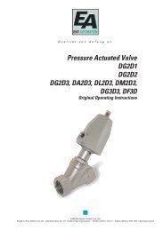
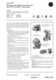
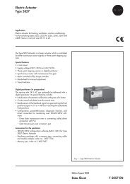
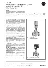
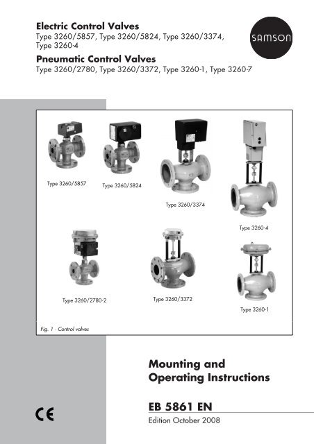
Electric Control ValvesType 3260/5857, Type 3260/5824, Type 3260/3374,Type 3260-4Pneumatic Control ValvesType 3260/2780, Type 3260/3372, Type 3260-1, Type 3260-7Type 3260/5857Type 3260/5824Type 3260/3374Type 3260-4Type 3260/2780-2 Type 3260/3372Type 3260-1Fig. 1 · Control valves<strong>Mounting</strong> <strong>and</strong><strong>Operating</strong> <strong>Instructions</strong><strong>EB</strong> <strong>5861</strong> <strong>EN</strong>Edition October 2008
Safety instructionsGeneral safety instructions The control valves are to be mounted, started up or serviced by fully trained<strong>and</strong> qualified personnel only, observing the accepted industry codes <strong>and</strong>practices. Make sure employees or third persons are not exposed to anydanger.All safety instructions <strong>and</strong> warnings in these instructions, particularly thoseconcerning assembly, start-up <strong>and</strong> maintenance, must be observed. The control valves fulfil the requirements of the European PressureEquipment Directive 97/23/EC. Valves with a CE marking have adeclaration of conformity that includes information about the appliedconformity assessment procedure. The Declaration of Conformity isavailable on request. For appropriate operation, make sure that the control valves are only usedin areas where the operating pressure <strong>and</strong> temperatures do not exceed theoperating values that are based on the valve sizing data submitted in theorder.The manufacturer does not assume any responsibility for damage caused byexternal forces or any other external influence!Any hazards that could be caused in the control valves by the processmedium, the operating pressure, the signal pressure or by moving parts areto be prevented using appropriate measures. Proper shipping <strong>and</strong> appropriate storage are assumed.Note! For installation <strong>and</strong> maintenance work on the control valve, make sure therelevant section of the plant has been depressurized <strong>and</strong>, depending on theprocess medium, drained as well. If necessary, allow the control valve to cooldown or heat up to reach ambient temperature before starting any work on it. The electric actuators have been designed for use in electrical powersystems. Observe the relevant safety regulations for wiring <strong>and</strong>maintenance. Only use power interruption devices that are protected against unintentionalreconnection of the power supply. Take special care when making adjustments on live parts. Do not removecovers!<strong>EB</strong> <strong>5861</strong> <strong>EN</strong> 3
Technical dataPneumatic actuatorsBench rangeType 2780 3372 3271 3) <strong>and</strong> 3277 3)bar0.41.00.42.01.42.3Maximum supply pressure bar 1.4 2.4 4 5 2.5 3.7 2.5 3.7 2.4 3.7Actuator cm² 120 240 350 700DN K VSSeat Max. Δp when p 2= 0 bar for mixing or diverting valves15 1·1.6·2.5·4 16 4 1) 4 1) – – – – – – – –20 6.3 20 4 1) 4 1) – – – – – – – –25 10 24 4 1) 4 1) – – – – – – – –32 16 32 1.7 1) 1.7 1) – – – – – – – –40 25 40 1.1 1) 1.1 1) – – – – – – – –50 40 40 1.1 1) 1.1 1) – – – – – – – –65 60 70 – – 3.8 4 1.9 3.1 3 4 – –80 80 70 – – 3.8 4 1.9 3.1 3 4 – –100 160 100 – – – – – – – – 3.1 4125 250 130 – – – – – – – – 1.8 4150 320 130 – – – – – – – – 1.8 4Electric actuators Type 5857 5824 3374-11 3374-10 3274-13/-17 3) 3274-11/-15/-21/-23 3)DN K VSSeat Max. Δp when p 2= 0 bar for mixing or diverting valves15 1·1.6·2.5·4 16 4 4 – – – –20 6.3 20 2.6 4 – – – –25 10 24 1.8 4 – – – –32 16 32 – 1.7 – – – –40 25 40 – 1.1 – – – –50 40 40 – 1.1 – – – –65 60 70 – 1.3 2) 4 4 – 480 80 70 – 1.3 2) 4 4 – 4100 160 100 – – – 2.8 4 1.9125 250 130 – – – 1.7 2.8 1.1150 320 130 – – – 1.7 2.8 1.11) Only with fail-safe action “Actuator stem retracts” · 2) Only with 5824-30 <strong>and</strong> rod-type yoke 1400-74143) Only with additional rod-type roke DN 65/80: 1890-8696, DN 100 <strong>and</strong> 125: 1400-88222.13.30.42.00.63.00.42.00.63.00.42.00.63.0<strong>EB</strong> <strong>5861</strong> <strong>EN</strong> 5
Design <strong>and</strong> principle of operation1 Design <strong>and</strong> principle ofoperationThe control valves consist of the Type 3260Three-way Valve <strong>and</strong> an electric,electrohydraulic or pneumatic actuator. Forvalve sizes DN 15 to 50, the connection betweenvalve <strong>and</strong> actuator is force locking,for sizes DN 65 to 150 it is form fit.The valves are available as mixing valves ordiverting valves. The respective version ismarked by a symbol on the valve body.When used as a mixing valve, the processmedia to be mixed are fed to the ports A<strong>and</strong> B. The combined flow is dischargedthrough port AB. For versions used as divertingvalves, the process medium entersthrough port AB, <strong>and</strong> the partial flows aredischarged at ports A <strong>and</strong> B.The position of the plug stem (6) determinesthe cross-sectional area of flow between theplug (3) <strong>and</strong> the seat (2). The plug positionis changed by the control signal acting onthe actuator. The electric actuators use athree-step signal. Actuators with an additionalpositioner can process analog signalsin the range 4 or 0 to 20 mA or 2 or 0 to10 V.The pneumatic actuators require signal pressureswith a bench range, for example, between0.2 to 1 bar or 0.4 to 2 bar, dependingon the required positioning force. Thesignal pressure is transmitted to the signalpressure connection.The Type 3372-05xx Electropneumatic Actuatorscan be actuated with analog signalsof 4 to 20 mA.1.1 VersionsType 3260/5857 · DN 15 to 25, PN 16,with Type 5857 Electric ActuatorType 3260/5824 · DN 15 to 80, PN 16,with Type 5824 Electric Actuator (DN 65<strong>and</strong> 80 with Type 5824-30 <strong>and</strong> yoke).Type 3260/2780 · DN 15 to 50, PN 16,optionally with insulating section, with Type2780-1 Pneumatic Actuator or Type 2780-2for integral positioner attachment.Type 3260/3372 · DN 65 to 80, PN 16,with Type 3372 Pneumatic Actuator.Type 3260/3374 · DN 65 to 150, PN 16,with Type 3374 Electric Actuator.Type 3260-1 · DN 65 to 150, PN 16, withyoke <strong>and</strong> Type 3271 Pneumatic Actuatorwith an effective area of 350 or 700 cm².Type 3260-4 · DN 65 to 150, PN 16, withyoke <strong>and</strong> Type 3274-11, 3274-13,3274-15 or 3274-17 Electrohydraulic Actuator.Type 3260-7 · DN 65 to 150, PN 16, withyoke <strong>and</strong> Type 3277 Pneumatic Actuator(effective area of 350 cm² or 700 cm²) forintegral positioner attachment.Note: For further details on electric or pneumaticactuators, refer to the mounting <strong>and</strong>operating instructions:For Type 5824 <strong>EB</strong> 5824 <strong>EN</strong>For Type 3374 <strong>EB</strong> 8331-1 <strong>EN</strong>For Type 3274 <strong>EB</strong> 8340 <strong>EN</strong>For Type 2780-2 <strong>EB</strong> 5840 <strong>EN</strong>For Type 3372 <strong>EB</strong> 8313 <strong>EN</strong>For Type 3271 <strong>EB</strong> 8310 <strong>EN</strong>For Type 3277 <strong>EB</strong> 8311 <strong>EN</strong>6 <strong>EB</strong> <strong>5861</strong> <strong>EN</strong>
Design <strong>and</strong> principle of operationAABAABBBFlow-diverting valveTransport protectionMixing valveDN 15 to 501 Body2 Seat3 Plug6 Plug stem632 1DN 65 to 150AABAABBBFlow-diverting valveMixing valveFig. 2 · Sectional drawings<strong>EB</strong> <strong>5861</strong> <strong>EN</strong> 7
Assembling valve <strong>and</strong> actuator2 Assembling valve <strong>and</strong>actuatorIn case the valve <strong>and</strong> actuator have notbeen assembled by the manufacturer, proceedas follows:2.1 Electric control valves2.1.1 Type 3260/5857(Type 5857 Actuator)1. Turn the h<strong>and</strong>wheel counterclockwise toretract the actuator stem as far as it willgo in the de-energized state.2. Place the actuator on the valve <strong>and</strong> securewith coupling nut (4) using a tighteningtorque of 20 Nm.2.1.2 Type 3260/5824(Type 5824 Actuator) DN 15 to 50:1. Turn the red h<strong>and</strong>wheel counterclockwiseto retract the actuator stem by approx.3 mm.2. Place the actuator on the valve <strong>and</strong> securewith coupling nut (4) using a tighteningtorque of 20 Nm (AF 36).DN 65 <strong>and</strong> 80:Requires rod-type yoke (9)Order no. 1400-74141. Remove stem connector clamps (7) fromthe actuator stem.2. Remove transport protection from valve.3. Place rod-type yoke (9) on top <strong>and</strong> securewith hex nut (8) (100 Nm, AF 36).4. Push actuator stem against the valve plugstem (6) <strong>and</strong> firmly connect them usingthe stem connector clamps (7).5. Place actuator on the rod-type yoke <strong>and</strong>secure with coupling nut (4) at thethreaded connection (20 Nm).2.1.3 Type 3260/3374(Type 3374 Actuator)1. Turn h<strong>and</strong>wheel to slightly retract the actuatorstem (4) into the actuator.2. Remove transport protection from thevalve. Place actuator together withrod-type yoke on the valve <strong>and</strong> securewith hex nut (8) (min. 100 Nm, AF 36).3. Pull the plug stem all the way up.4. Attach stem connector clamps (7) <strong>and</strong>screw tight.2.1.4 Type 3260-4(Type 3274 Actuator)Requires rod-type yoke (9):DN 65 to 80 Order no. 1890-8696DN 100 to 150 Order no. 1400-88221. Remove transport protection from thevalve. Place rod-type yoke (9) on top<strong>and</strong> secure with hex nut (8) (min.100 Nm).2. Firmly screw adapter (10) to plug stem(Ø 10 mm) using both stem connectorclamps (7).3. Place actuator on the rod-type yoke <strong>and</strong>secure with hex nut (5).4. Pull the adapter up until it contacts theactuator stem. Attach both stem connectorclamps (11) <strong>and</strong> screw tight with thehexagon bolts.8 <strong>EB</strong> <strong>5861</strong> <strong>EN</strong>
Assembling valve <strong>and</strong> actuatorType 5857DN 15 to 25Type 5824-30DN 65 to 800446Type 5824DN 15 to 50978464 Coupling nut5 Seat3 Hex nut6 Plug stem8 Hex nut9 Rod-type yoke10 Adapter11 StemconnectorType 32745Type 337411910767688DN 65 to 150Fig. 3 · <strong>Mounting</strong> electric actuators on valves<strong>EB</strong> <strong>5861</strong> <strong>EN</strong> 9
Assembling valve <strong>and</strong> actuator2.2 Pneumatic control valvesRequires rod-type yoke (9):DN 65 to 80 Order no. 1890-8696DN 100 to 150 Order no. 1400-88222.2.1 Type 3260/27801. Remove transport protection from thevalve.2. For actuators with fail-safe action "Actuatorstem extends", pressurize the signalpressure connection to retract the actuatorstem.3. Place actuator on the valve <strong>and</strong> securewith coupling nut (4).2.2.2 Type 3260/3372(Type 3372 Actuator)1. Remove transport protection from thevalve.2. Place actuator together with rod-typeyoke on the valve <strong>and</strong> secure with hexnut (8) using a min. tightening torque of100 Nm (width across flats 36).3. Pull the plug stem all the way up until itcontacts the actuator stem.4. Attach stem connector clamps (7) <strong>and</strong>screw tight.Type 2780 Type 3372 Type 3271 <strong>and</strong> 3277Type 33745467111074 Coupling nut5 Seat3 Hex nut6 Plug stem8 Hex nut9 Rod-type yoke10 Adapter11 Stem connectorDN 15 to 50DN 65 to 8068DN 65 to 150698Fig. 4 · <strong>Mounting</strong> pneumatic actuators on valves10 <strong>EB</strong> <strong>5861</strong> <strong>EN</strong>
Installation2.2.3 Type 3260-1 <strong>and</strong> -7(Type 3271 <strong>and</strong> Type 3277 Actuator)1. Remove transport protection from thevalve. Place rod-type yoke (9) on top<strong>and</strong> secure with hex nut (8) using a min.tightening torque of 100 Nm.2. Firmly screw adapter (10) to the plugstem (Ø10 mm) using both stem connectorclamps (7).3. Place actuator on the rod-type yoke <strong>and</strong>secure with hex nut (5).For actuators with fail-safe action "Actuatorstem extends", first apply a pressurewhich is slightly higher than the upperbench range value to the signal pressureconnection (see nameplate).4. Attach both stem connector clamps (11)<strong>and</strong> screw tight with the hex screws.Mixing valve for mixing serviceA ABFlowB3 Installation3.1 <strong>Mounting</strong> positionFor electric actuatorsType 5857: Not suspendedType 5824: Upright or horizontal mountingposition (degree of protetcion IP 54 only applieswhen installed upright)Type 3374: Not in upright position (see<strong>EB</strong> 8331 <strong>EN</strong>)Type 3274: Any mounting position.Pneumatic actuators can be installed in anymounting position.The valves are supplied as either mixing ordiverting valves. They can be used for bothmixing as well as diverting service (Fig. 5).Make sure that the system-related arrangementof inlet <strong>and</strong> outlet located at the portsA, B <strong>and</strong> AB comply with the symbols on thebody nameplate.Mixing valve for diverting serviceFlowReturn flowReturn flowABABFlow-diverting valve for mixing serviceFlowFlow-diverting for diverting serviceAB AFlowAABBReturn flowBReturn flowFig. 5 · Typical installations<strong>EB</strong> <strong>5861</strong> <strong>EN</strong> 11
InstallationCaution!Install the valve free of stress <strong>and</strong> with theleast amount of vibrations as possible.Pipeline routingTo allow the control valve to work properly,the pipeline upstream <strong>and</strong> downstream ofthe valve must be straight <strong>and</strong> free of obstructionsfor a length of at least 6 times thepipe diameter (DN). Contact SAMSON ifthis length cannot be met during installation.Clean out the pipeline thoroughly prior toinstalling the valve.Make sure you choose a place of installationthat allows you to freely access the controlvalve even after the entire plant has beencompleted.Thoroughly flush the pipelines prior to installation.Install a strainer (e.g. SAMSONType 2 NI) at the respective valve inlet toprevent that any sealing parts, weld spatter<strong>and</strong> other impurities carried along by theprocess medium impair the proper functioningof the valve, above all the tight shut-off.The valve must be installed free of stress. Ifnecessary, support the piping near the connections.3.2 Strainer Install a strainer upstream of the valve inletwith the filter element vertically suspended. Remember to leave enough space to removethe filter element. Install the strainer such that the directionof flow corresponds to the arrow.3.3 Additional mountinginstructionsWe recommend to install a h<strong>and</strong>-operatedshut-off valve upstream of the strainer <strong>and</strong>downstream of the control valve to be ableto shut down the plant for cleaning <strong>and</strong>maintenance, <strong>and</strong> when the plant is notused for longer periods of time.12 <strong>EB</strong> <strong>5861</strong> <strong>EN</strong>
Electrical connections4 Electrical connectionsWhen installing the electric connections,observe the regulations concerningelectrical power plant systems accordingto DIN VDE 0100 as well asthe regulations of your local powersupplier.The st<strong>and</strong>ard actuator versions are designedfor connection to three-point stepping controllers.The actuators also can be equippedfor inputs from 0 (2) to 10 V or 0 (4) to20 mA. For more details, refer to the applicablemounting <strong>and</strong> operating instructions.4.1 Type 3260/5857 ControlValveUse the 2.5 m cable for connection to thepower supply.Connect the control signals of the connectedcontroller to terminals eL <strong>and</strong> aL: When a voltage is applied to eL, the actuatorstem is retracted (direction of action“Stem retracts”). When a voltage is applied to aL, the actuatorstem is extended (direction of action“Stem extends“).ControllerLeLCeCeaLCaution!Only connect to the main power networkwhen the power is switched off.Only use power interruption deviceswhich ensure that the power cannot beswitched on unintentionally.Particularly for 24 V, 50 Hz actuators,use wires with a sufficiently largecross-section to guarantee that the permissiblevoltage tolerances ±10 % arenot exceeded.NwsaLbreLgreL Actuator stemretractsaL Actuator stemextendsws whitebr browngr greenNote! Decoupling capacitors Ce in the output circuitsof connected controllers must not exceed a value of2.5 nF to guarantee the proper functioning of theactuator.Fig. 6 · Electrical connection of Type 5857(version for three-step signal)<strong>EB</strong> <strong>5861</strong> <strong>EN</strong> 13
Electrical connections4.2 Types 3260/5824 <strong>and</strong>3260/5825 Control ValvesConnect the electric lines to the terminals viathe cable entries. To do so, the housingcover must be unscrewed. If necessary, thecable entries in the Type 3374 Actuator canbe replaced with M20 x 1.5 cable gl<strong>and</strong>s.Connect the control signals of the controllerto terminals eL <strong>and</strong> aL. When a voltage is applied to eL, the actuatorstem is retracted (”Actuator stemretracts“). When a voltage is applied to aL, the actuatorstem is extended (”Actuator stemextends“).Actuators operated in parallel must be connectedover separate contacts as control usinga single “Open” <strong>and</strong> “Closed” contactcan cause the actuators to hunt in their finalpositions.Type 5824/5825ControllerLType 3374eLaLActuator stemretractsActuator stemextendsCeCe– + N N LeLaL eL N N LaLMagnet in versionwith fail-safe actionType 5825 <strong>and</strong>Type 3374-2xLimit switchPotentiometersType 5824/5825 Type 337441 44 42 51 54 52 81 82 83 91 92 93 61 62 63Fig. 7 · Electrical connection for Type 5824 <strong>and</strong> Type 3374 with three-point stepping signal14 <strong>EB</strong> <strong>5861</strong> <strong>EN</strong>
Electrical connections4.3 Type 3260-4 Control ValveWith Type 3274 ActuatorUnscrew the lateral housing cover <strong>and</strong> introducethe wires through the cable gl<strong>and</strong>s.Connect the wires to the terminals accordingto the diagram label stuck in the cover or referto Fig. 8.Connect grounding conductor to the separategrounding conductor terminal on the innerwall of the housing.Note:Terminals N <strong>and</strong> L must always be suppliedwith voltage.If there is no supply voltage, the actuatorseither remain in their last position (3274-11to 3274-18) or move to fail-safe position(3274-21 to -23).Fuse:A fuse holder with a glass-tube fuse of5 x 20 mm is located on the PCB of the motorelectronic section:For 230 V, 50 Hz = T 1 (1 A time lag)For 110 V, 50 Hz = T 1.25 (1.25 A timelag)For 24 V, 50 Hz = T 6.3 (6.3 A time lag)Heating resistorϑMFeFaRetractsExtends"e" "a"e a a e1421) 2)N L aL eL a43 e53 81 1.31 1.32 1.33 2.31 2.32 2.33ControllerCaution:The controller output relays to control the input signalsaL <strong>and</strong> eL for the actuator must only be connected overthe terminal 81 (same potential).1) Switch “a” only in Types 3274-13/-14/-17/-18/-222) Switch “e” only in Types 3274-11...-18/-21/-23PE N LSafety interlock circuit inType 3274-2xFig. 8 · Electrical connection for Type 3274 with three-point stepping signal<strong>EB</strong> <strong>5861</strong> <strong>EN</strong> 15
Pneumatic connection5 Pneumatic connectionConnect the signal pressure connection forvalves with actuator version "Actuator stemextends" to the lower diaphragm case, <strong>and</strong>for actuator version "Actuator stem retracts"to the upper diaphragm case. Type 3277Actuators have the signal pressure connectionside-mounted on the actuator yoke atthe lower diaphragm case.6 Dimensions in mmNominal size DN 15 20 25 32 40 50 65 80 100 125 150Length L1 130 150 160 180 200 230 290 310 350 400 480Length L2 70 80 85 100 105 120 130 140 150 200 210Height H 51 51 51 61 61 61 71 71 112 112 112Height H2 158 158 158 168 168 168 265 265 306 306 306Weight without actuator kg 4 5 5.5 8.5 10 12 20 23 38 50 65Actuators Type 2780 3372 3271 <strong>and</strong> 3277 5857 5824 3374 3274-13Effective area cm 2 120 120 240 350 700Height H1 mm – – 65 80 199Diaphragm ∅ D mm 170 168 240 280 3903274-17Loading press. connection a G 1 8 G 3 8 G ¼ G 3 8 G 3 8Weight kg 2 3.71) Values in parentheses for Type 3277 Actuator5(9) 1) 8(12) 1) 22(26) 1) 0.7 1.3 4.2 11 1316 <strong>EB</strong> <strong>5861</strong> <strong>EN</strong>
6Dimensions in mmType 3260/5857 Type 3260/58541468080H11432 70H248 146 103203HL2L2L1DN 15 to 25Type 3260/337419360Type 3260-4L1DN 15 to 50235185DN 65 to 80Type 3260/3372Ø168294236HH2HL2L1DN 65 to 150L2L1DN 65 to 150DN 65 to 80Type 3260-1Type 3260-7Type 3260/2780-1ØDType 3260/2780-2ØDH1ØDaH1ØDa55100110HL2L1210HL2L1M 32x1.5H2L2L1H2L2L1a2(G 3 / 8 )DN 15 to 50DN 65 to 150<strong>EB</strong> <strong>5861</strong> <strong>EN</strong> 17
18 <strong>EB</strong> <strong>5861</strong> <strong>EN</strong>
<strong>EB</strong> <strong>5861</strong> <strong>EN</strong> 19
SAMSON AG · MESS- <strong>and</strong> REGELTECHNIKWeismüllerstraße 3 · 60314 Frankfurt am Main · GermanyPhone: +49 69 4009-0 · Fax: +49 69 4009-1507Internet: http://www.samson.de<strong>EB</strong> <strong>5861</strong> <strong>EN</strong>S/Z 2008-12