Data Sheet T 2178 EN Self-operated Temperature Regulators ...
Data Sheet T 2178 EN Self-operated Temperature Regulators ...
Data Sheet T 2178 EN Self-operated Temperature Regulators ...

Create successful ePaper yourself
Turn your PDF publications into a flip-book with our unique Google optimized e-Paper software.
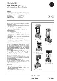
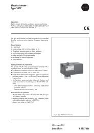
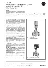
<strong>Self</strong>-<strong>operated</strong> <strong>Temperature</strong> <strong>Regulators</strong>Series 43<strong>Temperature</strong> Regulator with Hydraulic ControllerType 43-8Type 43-8 NApplication<strong>Temperature</strong> regulation of instantaneous water heaters in smalldistrict heating units, particularly in single- and two-familydwellings · Valve closes when temperature increasesThe regulators are suitable for use with plate heat exchangersfor domestic hot water (DHW) heating, particularly in smallresidential units. Fast-responding thermostats regulate thewater temperature to the desired value without delay while thehydraulic control element closes the control valve immediatelyafter tapping has been completed. This prevents the heatedDHW from reheating. In addition, temperature peaks do notoccur any longer and thus scaling (lime deposits) in the heatexchanger are avoided.Moreover, the regulator switches to a reduced idle temperaturethat prevents the heating water supply lines from cooling off.This ensures that hot water is immediately available for the nexttapping.The connections available as accessories enable operation withor without circulation of the heated DHW.Special features• Low-maintenance P-regulators requiring no auxiliaryenergy• Regulation of small instantaneous water heaters• Compact design• Simple installation and operation• Prevention of temperature peaks and reduction of lossduring idle operation (reduced idle temperature)• Stable regulation already at tapped quantity of 2 l/minute• Idle temperature regulation• Fast-responding vapor pressure thermostatsFig. 1 · Type 43-8 <strong>Temperature</strong> Regulator with Hydraulic Controller(regulator including accessories and indicated heat exchanger)VersionsThe Type 43-8 and Type 43-8 N <strong>Regulators</strong> function the sameway, the only difference between them being that the technicalfeatures of the Type 43-8 N have been tailored to therequirements of local heat supply networks. Its overall height isapprox. 20 mm lower than that of the Type 43-8. As a result,the regulators are not interchangeable.The regulators consist of a control thermostat (vapor pressurethermostat), a hydraulic control element, and a valve. They canadditionally be equipped with a Type 2439 K Safety<strong>Temperature</strong> Limiter.Type 43-8 (43-8 N)Type 2430 K Vapor Pressure Thermostat · Set point range 45to 65 °C · In combination with Type 2432 K Valve (2432 N)Red brass or hot-pressed brass body · DN 15 1) · PN 25(PN 16) · For liquids up to 150 °C (120 °C) · Permissibledifferential pressure Δp = 20 bar (4 bar) · K VS = 2.5 · Sensormade of CrNiMo steel · Observe mounting position!Type 2438 K Hydraulic Controller · Red brass body · Idletemperature approx. 8 K (optionally 15 K) below adjusted setpoint · Required differential pressure at control element 0.4 to0.6 bar · PN 161)Other versions on requestAssociated Information <strong>Sheet</strong> T 2170 <strong>EN</strong> Edition December 2008<strong>Data</strong> <strong>Sheet</strong>T <strong>2178</strong> <strong>EN</strong>
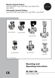
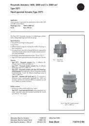
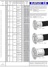
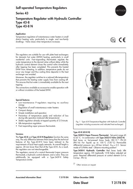
Principle of operation (see Fig. 2)Fast-responding vapor pressure sensors are used to regulate thetemperature of instantaneous water heaters.The temperature of the heated DHW creates a pressure in thesensor that corresponds to the actual value. This pressure istransferred through the capillary tube (8) to the operatingelement (13) and converted into a positioning force, which iscompared to the force of the set point spring (10). The forceratio causes the plug in the valve (1) to move.Depending on the travel, an annular gap forms between theseat (2) and the plug (3) that determines the flow rate of theheating water. A temperature increase at the sensor causes thevalve plug to close, thus reducing the flow rate of the heatingwater.Upon tapping hot water, a pressure difference of Δp = p 1 –p 2 iscreated above the baffle plate (6). The resulting force opposesthe force of the compression spring (7) that acts in closingdirection and causes the valve (1) to open. Once hot watertapping has been completed, the pressure balance is restored.The force of the compression spring causes the valve plug tomove in closing direction and the heat flow is interrupted. At thesame time, the temperature set point of the thermostat drops byapprox. 8 K (optionally 15 K) to reach the reduced idletemperature. As a result, reheating with temperature peaks aswell as cooling off of the supply lines is prevented. Hot water isimmediately available for the next tapping.Vapor pressure thermostatThermostat operating according to the vapor pressureprinciple. Due to the fast response time of approx. 3 s, thesethermostats are particularly suitable for use in plate heatexchangers 1) .1)Other versions on requestInstallationThe sensor must be installed in the best possible location tomake ideal use of the thermostat’s fast response. With plateheat exchangers, this location is directly upstream of the heatexchanger’s hot water outlet.– Install the temperature sensor such that the sensor reacheshorizontally into the hot water duct when the heat exchangeris mounted, observing a maximum deviation of ±5° from thehorizontal position. The notch at the end of the sensor mustpoint upward (see View A).– Only install the sensor without thermowell.– Observe a distance of approx. 5 mm between the tip of thesensor and the rear of the housing.– Install the plate heat exchanger such that the heating waterflows vertically between the plates.– The heat exchanger connections for cold water and the (district)heating water return pipe are located at the bottom; theconnections for hot water and the (district) heating waterflow pipe can be found at the top.– The ambient temperature at the set point adjuster must notexceed 35 °C.Type 2430 KControl ThermostatType 2438 KHydraulic ControllerCold watersupplyp 1p 2Hot waterreturn pipeType 2432 KGlobe Valve13121110987654321 Valve body 7 Compression spring2 Seat (replaceable) 8 Capillary tube3 Plug 9 Set point adjuster4 Plug stem 10 Set point spring5 Valve spring 11 Positioning bellows6 Baffle plate 12 Pin of operating element13 Operating elementFig. 2 · Principle of operationPrinciple of operation · Vapor pressure thermostatThe temperature sensor is filled with a liquid that vaporizes dependingon the temperature. In the sensor, a pressure proportionalto the temperature is created. The pressure is transmittedthrough the capillary tube onto the positioning bellows and convertedinto a positioning force, which causes the valve plug tomove depending on the adjusted set point.Plate heat exchangermax. ±5˚5mm<strong>Temperature</strong> sensor- vapor pressure thermostat -Cold water connectionto heat exchanger(turned into plane ofprojection)1Hot water outletConnection piecewith temperaturesensorAView A<strong>Temperature</strong> sensor,notch facing upwardFig. 3 · Installing the sensor2 T <strong>2178</strong> <strong>EN</strong>
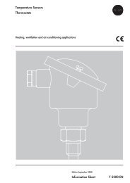
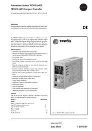
Table 1 · Technical dataType 2432 Valve Type 43-8 Type 43-8 NNominal size DN 15 1)K VS 2.5Nominal pressure (according to DIN 2401) PN 25 PN 16Max. perm. differential pressure 20 bar 6 barMax. perm. valve temperature 150 °C 120 °CType 2430 K Control ThermostatSet point range 45 °C to 65 °CCapillary tube 2 m (special version: 5 m)Max. perm. temperature at sensor30 K above adjusted set pointMax. perm. temperature at set point adjuster 35 °CPerm. pressure at sensor PN 40Type 2438 K Hydraulic ControllerMin. differential pressure at control element0.4 to 0.6 barNominal pressure PN 16Idle temperatureApprox. 8 K (optionally 15 K) below adjusted set pointMin. temperature difference betweenflow temperature and temperature set point10 KMax. flow rate26 l/minute1) Other values on request2) In addition to a Type 2430 K Control Thermostat, a Type 2439 K Safety <strong>Temperature</strong> Limiter can be used. Observe changed dimensions!Table 2 · Materials · Material numbers according to DIN <strong>EN</strong>Body CW602N (hot-pressed brass) · CC491K (red brass Rg 5)Valve seat CW602N / stainless steel 1.4305Valve plug1.4104 and dezincification-resistant brass with EPDM soft sealingValve spring and spring in Type 2438 K Stainless steel 1.4310Baffle plate 1.4301<strong>Temperature</strong> sensorSet point adjusterCapillary tubeSensorCopperCrNiMo steelGlass fiber reinforced PETPField of applicationThe quality of the domestic water to be controlled determines thefield of application of the regulator. The water quality shall meetthe requirements specified in Table 3.Domestic hot water heated in an instantaneous heatingsystem with Type 43-8Table 3 · Water qualityDomestic waterpH Min. 7/max. 10Chlorideconcentration–HCO32– >1.5SO4Max. 150 mg/lCarbonate hardnessTotal hardnessMin. 5° dH (German hardness)Max. 12° dH (German hardness)1 District heating supply2 District heating return flow3 Cold water4 Hot waterFig. 4 · Domestic hot water in an instantaneous heating system3 T <strong>2178</strong> <strong>EN</strong>
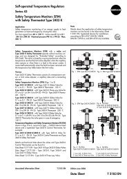
AccessoriesConnection piece (1) to hot water tapping point (G ¾ or G 1)With/without sensor pocket (G ¾ or G1) · Including flat gasketFor temperature sensor Ø 12, Rg 5To hot watertapping pointHeating waterflow pipeHotwaterCold water supply · Corrugated pipe (4) with/without circulationpipe connection (2) for connection to heat exchanger (G ¾ or G 1)Including flat gasket1Hot water return pipe · Double nut (5) of brass (G ¾ or G 1) forconnection to heat exchanger · Welding end (3) with connection nutIncluding flat gasketConnection dimensions for heat exchangerHeat exchanger connectionG¾Double nut (5)Distance “a” in mm 40 to 45G148 to 5269 to 73Cold watersupply25mmConnectionG ¾orG 1aH ≥ 260mm(240mm) 1)Corrugated pipe (4) connectionWith/without circulation345Heatingwater return pipeColdwaterFig. 5 · Regulator with accessories1) For Type 43-8NDimensions in mmØ 12Ø 76G¾ /G1G¾241 1) 6515 35G¾30190G¾1) For Type 43-8 N: 221 mm43With Type 2439 K Safety <strong>Temperature</strong> Limiter: 361 mm65Fig. 6 · DimensionsOrdering text<strong>Temperature</strong> Regulator with Hydraulic ControllerType 43-8 / Type 43-8 N · Valve DN 15, K VS 2.5Heat exchanger Type …Heat exchanger connection G ¾ / G 1With/without circulation pipe connectionSensor with/without screw glandOptionally, special version …Optionally, accessories ...Specifications subject to change without notice.SAMSON AG · MESS- UND REGELTECHNIKWeismüllerstraße 3 · 60314 Frankfurt am Main · GermanyPhone: +49 69 4009-0 · Fax: +49 69 4009-1507Internet: http://www.samson.deT <strong>2178</strong> <strong>EN</strong>