Electric Actuators Type 5824 (without fail-safe action) Type 5825 ... - ii
Electric Actuators Type 5824 (without fail-safe action) Type 5825 ... - ii
Electric Actuators Type 5824 (without fail-safe action) Type 5825 ... - ii
- No tags were found...

You also want an ePaper? Increase the reach of your titles
YUMPU automatically turns print PDFs into web optimized ePapers that Google loves.
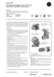
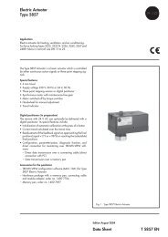
<strong>Electric</strong> <strong>Actuators</strong><strong>Type</strong> <strong>5824</strong> (<strong>without</strong> <strong>fail</strong>-<strong>safe</strong> <strong>action</strong>)<strong>Type</strong> <strong>5825</strong> (with <strong>fail</strong>-<strong>safe</strong> <strong>action</strong>)Application<strong>Electric</strong> actuators designed for control valves used in heating,ventilation and air-conditioning systems as well as in processengineering and industrial energy transfer systemsThe linear actuators are particularly suitable for attachment toSAMSON <strong>Type</strong>s 3260, 3222, 3226, 3213, 3214 and V2001Valves. In addition, they can be used as additional electric actuatorson self-operated differential pressure and flow regulators.Special features:• <strong>Type</strong> <strong>5824</strong> Actuator <strong>without</strong> <strong>fail</strong>-<strong>safe</strong> <strong>action</strong> and <strong>Type</strong> <strong>5825</strong>with <strong>fail</strong>-<strong>safe</strong> <strong>action</strong>• Three-point stepping version with synchronous motor andmaintenance-free gearing or version with digital positionerand stepper motor• Switched off by torque-dependent switches• <strong>Type</strong> <strong>5824</strong> with manual override (handwheel)• Optional three-point stepping versions:– With faster motor (half the standard transit time)– With two adjustable limit switches– With potentiometerDigital positioner• Automatic initialization when applying the operating voltage• Reversed direction of <strong>action</strong> by moving a slide switch• Current travel calculated from transit time• Operating states and errors indicated by LEDs• Adjustable positioning rates (10 to 30 s)• Blocking protection• Adjustable input voltage range• Configuration, parameterization, diagnostics and onlineconnection for monitoring in the TROVIS-VIEW software– Direct data transmission using connecting cable (onlineconnection)– Indirect data transmission using memory penAccessories for version with digital positioner– TROVIS-VIEW software module (6661-1059) for <strong>Type</strong> <strong>5824</strong>or <strong>Type</strong> <strong>5825</strong> <strong>Electric</strong> Actuator– Hardware package including memory pen, connecting cableand module adapter, order no. 1400-7704– Memory pen, order no. 1400-7697Fig. 1 · <strong>Type</strong> <strong>5824</strong>-10 <strong>Electric</strong> Actuator(version <strong>without</strong> digital positioner)<strong>Type</strong>ValveattachmentRatedtravelOptional versionwith digitalpositionerVersions <strong>without</strong> <strong>fail</strong>-<strong>safe</strong> <strong>action</strong><strong>5824</strong>-10 Force-locking 6 (7.5) mm Yes1) <strong>5824</strong>-13 Force-locking 6 mm No<strong>5824</strong>-20 Force-locking 12 mm Yes1) <strong>5824</strong>-23 Force-locking 12 mm No<strong>5824</strong>-30 Form-fit 15 mm YesVersions with <strong>fail</strong>-<strong>safe</strong> <strong>action</strong>"actuator stem extends" or "actuator stem retracts"<strong>5825</strong>-10/-15 Force-locking 6 (7.5) mm Yes<strong>5825</strong>-13 1) /–– Force-locking 6 mm No<strong>5825</strong>-20/-25 Force-locking 12 mm Yes<strong>5825</strong>-23 1) /–– Force-locking 12 mm No<strong>5825</strong>-30/-35 Form-fit 15 mm Yes1) Version with faster motor (<strong>Type</strong> <strong>5825</strong>-x3) only with <strong>fail</strong>-<strong>safe</strong> <strong>action</strong>"actuator stem extends"Associated Information Sheet T 5800 EN Edition August 2009Data SheetT <strong>5824</strong> EN
Principle of operation (Fig. 2)The three-point stepping version consists of a reversible synchronousmotor and maintenance-free gearing. The synchronousmotor is switched off by torque-dependent switches in theend positions or in case of overload.In the version with digital positioner, the stepper motor allowsfor supply by frequency-independent voltages.The motor's force is transmitted to the actuator stem (3) via thegearing and a crank disk. When the actuator stem extends, itpushes against the valve's plug stem. When the actuator stemretracts, the return spring in the valve causes the plug stem tofollow the movement (force-locking connection).Actuator and valve are connected by the coupling nut (4).Form-fit valves <strong>without</strong> return spring can be combined with a<strong>Type</strong> <strong>5824</strong>-30 or <strong>Type</strong>s <strong>5825</strong>-30/-35 <strong>Actuators</strong> using a yokeor adapter:– Yoke for V2001 Valves: order no. 1400-7414– Adapter for other valve types: order no. 1400-7415<strong>Type</strong> <strong>5824</strong>The actuator <strong>without</strong> <strong>fail</strong>-<strong>safe</strong> <strong>action</strong> is equipped with ahandwheel (2) to manually move the valve to the desired position.The direction of <strong>action</strong> and travel can be read off the travelindication scale (9).<strong>Type</strong> <strong>5825</strong>The actuator with <strong>fail</strong>-<strong>safe</strong> <strong>action</strong> largely corresponds to the<strong>Type</strong> <strong>5824</strong> described above. However, it contains a spring assembly(8) and an electromagnet, which move the valve to its<strong>fail</strong>-<strong>safe</strong> position when de-energized. The <strong>Type</strong> <strong>5825</strong> is availablewith <strong>fail</strong>-<strong>safe</strong> <strong>action</strong> actuator stem extends (when thepower supply <strong>fail</strong>s) or actuator stem retracts (when the powersupply <strong>fail</strong>s).A handwheel (2) is not fitted. Before adjusting the actuatormanually, the actuator must be switched off and the cover (1.1)removed. An Allen key is used to adjust the actuator. The actuatorimmediately returns to its initial position when the key is released.<strong>Type</strong>tested versionThe <strong>Type</strong> <strong>5825</strong> <strong>Electric</strong> Actuator with <strong>fail</strong>-<strong>safe</strong> <strong>action</strong> "actuatorstem extends" for force-locking attachment is typetested by theGerman technical surveillance association TÜV according toDIN EN 14597 in combination with different SAMSON valves.Registration numbers are available on request.Version with faster motor (three-point stepping version)The <strong>Type</strong>s <strong>5824</strong>-13/-23 and <strong>Type</strong>s <strong>5825</strong>-13/-23 areequipped with a faster motor in a housing flanged to the back ofthe actuator.3408 9 1 2 1.1 1.2Additional electrical equipment612 171 Housing1.1 Cover1.2 Cable entry2 Handwheel, <strong>Type</strong> <strong>5824</strong>3 Actuator stemFig. 2 · <strong>Type</strong> <strong>5824</strong> and <strong>Type</strong> <strong>5825</strong>Three-point stepping version Potentiometer · The potentiometer is linked to the gearingand allows for a resistance signal between 0 and 1000 Ωproportional to the valve travel. Limit switches · Optionally, the actuators can be equippedwith two limit switches, which are actuated by continuouslyadjustable cam disks.The supply voltage as well as the inputs and outputs arenot electrically isolated. The two additional limit switchescannot be retrofit.Version with digital positioner Positioners guarantee a predetermined assignment betweenvalve position and control signal.For position feedback, an 0 to 10 V signal can be pickedoff terminals 32 and 33.The version with positioner allows the characteristic to bereversed and is suitable for split-range operation. Limit switches (positioners with 24 V DC/AC only) · Optionally,the actuators can be equipped with two limitswitches, which are actuated by continuously adjustablecam disks.The supply voltage as well as the inputs and outputs arenot electrically isolated. The two additional limit switchescannot be retrofit. Priority circuit · When limit switches are used, the actuatorcan optionally be equipped with a priority circuit.104 Coupling nut8 Spring assembly, <strong>Type</strong> <strong>5825</strong>9 Travel indication scale10 Housing for faster motor(optional)2 T <strong>5824</strong> EN
Settings of the digital positionerThe positioner settings can be edited in the TROVIS-VIEW software.ConfigurationDefaultsettingsAdjustment rangeInput variableLower range value 0.0 0.0 to 7.5Upper range value 10.0 2.5 to 10.0Unit V V/mAPosition feedback signalLower range value 0.0 V 0.0 to 10.0 VUpper range value 10.0 V 0.0 to 10.0 VReference variableDetect input variable<strong>fail</strong>ureReference value upon inputvariable <strong>fail</strong>ureInternal reference variableNoInternalNo/YesInternal/Last travel value0.0 % 0.0 to 100.0 %Priority position No No/YesPriority position whenstemExtended Extended/RetractedFinal position guiding:actuator stem extends1.0 % 0.0 to 49.9 %Final position guiding:actuator stem retracts99.0 % 50.0 to 100.0 %InstallationBefore attaching the actuator to the valve, make sure the actuatorstem is retracted. To do so in <strong>Type</strong> <strong>5825</strong> with <strong>fail</strong>-<strong>safe</strong> <strong>action</strong>"actuator stem extends", remove the cover and turn the actuatingshaft counterclockwise usinga4mmAllen key to retract theactuator stem. Hold the actuator stem in this position. Proceedby tightening the coupling nut.<strong>Electric</strong>al connectionThe diagram on page 6 of this data sheet illustrates the actuator'selectrical connections.Ordering text<strong>Type</strong> <strong>5824</strong>-... or <strong>Type</strong> <strong>5825</strong>-... <strong>Electric</strong> Actuator– Three-point stepping versionVoltage: 230 V, 50 Hz24 V, 50 Hz120 V, 60 HzAdditional electrical equipment:With/<strong>without</strong> limit switchesWith/<strong>without</strong> potentiometer– Version with digital positioner:Voltage: 24 V DC24 V, 50 and 60 HzAdditional electrical equipment:With/<strong>without</strong> limit switchesWith/<strong>without</strong> potentiometerFunctionsBlocking protection ofvalveValve travelNoNo/YesTravel 100.0 % 30.0 to 130.0 %Travel adjustment Absolute Absolute/RelativeSpeed of stem movement Normal Slow/Normal/FastDead band (switchingrange)1.0 % 0.5 to 5.0 %CharacteristicLinearLinear/Equal percentage/Reverse equal percentage/User-defined3 T <strong>5824</strong> EN
Technical data · Three-point stepping versionThree-point stepping version <strong>Type</strong> <strong>5824</strong> <strong>5825</strong>-10 -13 -20 -23 -30 -10 -13 -20 -23 -30 -15 -25 -35Fail-<strong>safe</strong> function Without WithFail-<strong>safe</strong> <strong>action</strong> – Stem extends Stem retractsRated travel mm 6 1) 6 12 12 15 6 1) 6 12 12 15 6 1) 12 15Transit time for rated travel s 35 1) 18 70 36 90 35 1) 18 70 36 90 35 1) 70 90Transit time for <strong>fail</strong>-<strong>safe</strong> <strong>action</strong> s – 4 4 6 6 7 4 6 7Nominal thrustStem extends N 700 700 500 280 500 280Stem retracts N – 700 – 280 – 280Nominal thrust of <strong>safe</strong>ty spring N – 500 280 – 3) 280AttachmentForce-locking • • • • • • • • • •Form-fit • • •<strong>Electric</strong>al connection24 V, 50 Hz • • • • • • • • •230 V, 50 Hz • • • • • • • • • • • • •120 V, 60 Hz • • • • • • • • •Power consumption, approx. VA 3 6 3 6 3 4 8 4 8 4 4 4 4Handwheel Yes Optional 2)Permissible temperaturesAmbient 0 to 50 °CStorage –20 to 70 °CAt connecting stem 0 to 130 °CDegree of protection IP 54 (upright position, according to DIN IEC 529)Class of protection II (according to VDE 0106)Overvoltage category II (according to VDE 0110)Degree of contamination 2 (according to VDE 0110)Noise immunity EN 61000-6-2Noise emission EN 61000-6-3Weight kg 0.75 1.00 0.75 1.00 0.75 1.00 1.25 1.00 1.25 1.00 1.00 1.00 1.00Additional electrical equipment2 limit switches · Max. 230 V, 3 ACannot be retrofit!1 potentiometer · 0 to 1000 Ω±15 % (90 % of final value at ratedtravel); max. 1 mA, 5 VMaterialsHousing, coverCoupling nut• • • • • • • • • • • • •• • • • • • • • •Plastic (PPO with glass fiber reinforcement)Brass1) <strong>Actuators</strong> with 6 mm travel can also be used for valves with 7.5 mm travel (45 s transit time)2) Manual override using 4 mm Allen key after removing the cover; actuator always moves to <strong>fail</strong>-<strong>safe</strong> position when <strong>fail</strong>-<strong>safe</strong> <strong>action</strong> has beentriggered3) Safety spring pulls actuator stem to retracted end position; valve operated by valve spring4 T <strong>5824</strong> EN
Technical data · Actuator with digital positioner<strong>Actuators</strong>with digital positioner<strong>Type</strong> <strong>5824</strong> <strong>5825</strong>-10 -20 -30 -10 -20 -30 -15 -25 -35Fail-<strong>safe</strong> function Without WithFail-<strong>safe</strong> <strong>action</strong> – Stem extends Stem retractsRated travel mm 6 1) 12 15 6 1) 12 15 6 1) 12 15Transit time for rated travel2) 3)s45/31/1789/61/33111/76/4145/31/1789/61/33111/76/4145/31/1789/61/33Transit time for <strong>fail</strong>-<strong>safe</strong> <strong>action</strong> s – 4 6 7 4 6 7Nominal thrust Stem extends N 700 500 280 500 280Nominal thrust of <strong>safe</strong>ty spring N – 500 280 – 4) 280AttachmentForce-locking • • • • • •Form-fit • • •<strong>Electric</strong>al connection 6)Operation with 24 V DC(–10 %, +20 %)• •Operation with 24 V, 50 and 60 Hz • •Power consumptionOperation with 24 V DC(–10 %, +20 %)VA 3 5Operation with 24 V, 50 and60 HzVA 7 10Manual override Yes Optional 5)Permissible temperaturesAmbient 0 to 50 °CStorage –20 to 70 °CAt connecting stem 0 to 130 °CDegree of protection IP 54 (upright position, according to DIN IEC 529)Class of protection II (according to VDE 0106)Overvoltage category II (according to VDE 0106)Degree of contamination 2 (according to VDE 0110)Noise immunity EN 61000-6-2Noise emission EN 61000-6-3Weight kg 0.75 1.00Additional electrical equipment111/76/412 limit switches · Max. 230 V, 3 ACannot be retrofit!• •MaterialsHousing, coverCoupling nutPlastic (PPO with glass fiber reinforcement)Brass1) <strong>Actuators</strong> with 6 mm travel can also be used for valves with 7.5 mm travel (45 s transit time)2) Adjustable; default settings in bold print3) With a fast positioning speed and 24 V DC supply voltage, make sure the voltage does not fall below the specified value4) Safety spring pulls actuator stem to retracted end position; valve operated by valve spring5) Manual override using 4 mm Allen key after removing the cover; actuator always moves to <strong>fail</strong>-<strong>safe</strong> position when <strong>fail</strong>-<strong>safe</strong> <strong>action</strong> has beentriggered6) Additionally, an actuator with 100 to 240 V, 50 and 60 Hz is in preparation5 T <strong>5824</strong> EN
<strong>Electric</strong>al connectionThree-point stepping versionControllerCeCeThree-point stepping signalCaution! The interference suppression capacitors C e in the output circuitof the connected controller must not exceed a value of 2.5 nF toensure the proper functioning of the actuator. A special actuator versionis available on request for connection to controllers with largerinterference suppression capacitors.N + – N LN eL aL N LeLStem retracts<strong>Type</strong> <strong>5825</strong> onlyaLStem extendsAdditional electrical equipment for actuators in three-point stepping versionLimit switches41 44 42 51 54 52Potentiometer63 62 61Actuator with digital positioner… with 24 V DCInput… with 24 V ACInputOutputOutput<strong>Type</strong> <strong>5825</strong> only<strong>Type</strong> <strong>5825</strong> onlyAdditional electrical equipment for actuators with digital positionerLimit switches41 44 42 51 54 52Priority circuit82 836 T <strong>5824</strong> EN
Dimensions in mm<strong>Type</strong>s <strong>5824</strong>-10/-20 and <strong>5825</strong>-10/-20/-15/-25<strong>Type</strong>s <strong>5824</strong>-30, <strong>5825</strong>-30/-3540146Actuator<strong>without</strong>yoke611382484410315 mmtravel46.510<strong>Type</strong>s <strong>5824</strong>-13/-23 and <strong>5825</strong>-13/-23406146<strong>Type</strong> <strong>5824</strong>-30Actuatorwith yoke1400-741461138218Ø7015 mmtravel203481251 (33)4410350136136Specifications subject to change <strong>without</strong> notice.7 T <strong>5824</strong> EN
SAMSON AG · MESS- UND REGELTECHNIKWeismüllerstraße 3 · 60314 Frankfurt am Main · GermanyPhone: +49 69 4009-0 · Fax: +49 69 4009-1507Internet: http://www.samson.deT <strong>5824</strong> EN2010-01