Operating Instructions e@syDrive 4425, 4426. - Centerline Inc
Operating Instructions e@syDrive 4425, 4426. - Centerline Inc
Operating Instructions e@syDrive 4425, 4426. - Centerline Inc

You also want an ePaper? Increase the reach of your titles
YUMPU automatically turns print PDFs into web optimized ePapers that Google loves.
<strong>e@syDrive</strong> <strong>4425</strong>, <strong>4426.</strong>A 1.3 PrecautionsSafe operation and protection of the device is ensured only by proper use, in accordance with the User Manual,with the tools approved for this purpose. The following should also be observed:• the work safety regulations,• the accident prevention regulations.Before installation and commissioning of this device, please read this safety and warning information carefullyand observe all warning signs mounted on the device.■ The frequency inverter type <strong>4425</strong>/4426 controls dangerously rotating mechanical parts. If these <strong>Operating</strong><strong>Instructions</strong> are not followed, severe damage to property, injuries and even death may result.■ Safe operation of this device depends on the proper installation, handling and operation of the device.■ Only appropriately qualified personnel may put this device into operation, maintain it and work on it.Connection, commissioning and rectification of faults may be performed only by specialists.■ The device has no mains switch. When working on the open device, it must be completely disconnected fromthe mains beforehand. The device has no mains input fuses.■ This device may start up automatically with certain settings after a mains failure.■ This device may not be used as an “emergency stop mechanism” (see EN 60204).■ The device may be used only for the purpose intended by the manufacturer. Unauthorized modifications andthe use of additional equipment not recommended by the manufacturer can cause fires, electric shocks andinjuries.DefinitionsASM motorBLDC-MotorBLDCS-MotorEEPROMDangerNotePC Browser-OperationDFÜRAS- ModemMicrostepstartupNormalstate3-phase asynchronous motor3-phase brushless DC motor without position sensorsThe inverter performs the position synthesis by measuring the motor voltage (e.m.f.).3-phase brushless DC motor with position sensorsElectrically Erasable Program Memory. In the EEPROM, all important alterable data (parameters,calibration values) of the frequency inverter type <strong>4425</strong>/4426 are stored and the dataremain stored even during a voltage failure.In the context of this User Manual and of the warnings mounted on the device, this meansthat death, serious injury or considerable damage to property may occur if the correspondingprecautions are not taken.In the context of this User Manual, a note constitutes important information which is of particularimportance for the understanding and the operation of the device.The configuration and , as required, the operation of the inverter is carried out using astandard PC Browser (MS-Internet-Explorer).Data transmissionRemote Access Service (Fern-Zugangs-Dienst)With microstep startup, the BLDC motor is operated as a synchronous motor with constantcurrent. The output frequency is slowly increased from 0 Hz to the startup frequency, afterwhich the system switches to regulated motor running. The microstep startup permits startupof sensor-free BLDC motor with large centrifugal masses (e.g. vacuum pumps) for which thenormal startup fails owing to the large mass moment of inertia.If no error occurs after switching on, the standard display appears on the LCD displayH1 and the LED H3 “Operation” (green) lights up. This machine state is called the normalstate. By repeatedly pressing the key !(cancel, transfer), it is possible to exit the state andreturn to it.4
<strong>e@syDrive</strong> <strong>4425</strong>, <strong>4426.</strong>ConfigurationQualifiedpersonnelStandarddisplayCautionWarningURLIP-AdressConfiguration is the operating procedure for setting up the inverter for use, motor settings anddevice-specific settings being implemented via the control panel. It is also possible to displaydifferent measured values.are in the context of this User Manual persons who are familiar with the installation, assembly,commissioning and operation of the product and with the possible dangers.With parameter P4-display, the value or the value combination (combi display) whichis displayed in the normal state can be selected. This is the standard display.In the context of the User Manual and of the warning signs mounted on the device, thismeans that slight injury or damage to property may occur if the corresponding precautions arenot taken.In the context of the User Manual and of the warning signs mounted on the device, thismeans that death, serious injury and considerable damage to property may occur if the correspondingprecautions are not taken.Uniform Resource Locator /Address details in browser command lines.Internet Protokoll Adress5
<strong>e@syDrive</strong> <strong>4425</strong>, <strong>4426.</strong>A 1.4 Purpose and potential applicationsKaVo frequency inverters, type 4452, have been specially constructed for the operation of three-phase asynchronousmotors (ASM) and brushless DC motors (BLDC), as used in spindles, e.g. for grinding, cutting anddrilling units on machine tools.They can also be used for operating motors which are constructed from motor elements and serve, for example,as a drive for test stands or other physical equipment (e.g. vacuum pumps, centrifuges, optical systems etc.).Gentle operation of the motors is achieved by the pulse amplitude modulation (PAM) used.Specifically, the following motor types can be operated:- Asynchronous motors (ASM)- Brushless DC motors without sensors (BLDC)- Brushless DC motors with sensors (BLDCS)An integrated load compensation offers high speed constancy and - through low idling currents - avoids unnecessaryheating up of the connected motors.At the stop command, the connected motor is braked until it stops.The control and monitoring of the inverter are performed by several microprocessors. This ensures high reliabilityand flexibility.A firmware update can be performed on a PC via a serial interface (RS232); contact KaVo in this context.The inverter can be completely remote-controlled. Various inputs and outputs are freely programmable.6
<strong>e@syDrive</strong> <strong>4425</strong>, <strong>4426.</strong>A 1.5 Technische Daten Umrichter <strong>e@syDrive</strong> <strong>4425</strong>ConfigurationOperationDisplayvia the serial interface using a standard PCB browservia an SPS-compatible remote control or using a standard PC browser(via the serial interface)lamps for operation (green) H4 and overload (yellow) H5Dimensions approx. 75 mm wide, 310 mm high, 215 mm deep, for switchgear housingsee also B1.<strong>Operating</strong>temperature 0 ... 40°CHumidity of the air: lower than 90 % relative humidity, non-condensatingWeightTests andstandardsapprox. 3,0 kgVDE tested according to EN 61800-5-1 CSA to UL 508CEMV to EN 61800-3EMC according to EN 61800-3Ingress protection IP20 according to DIN 40050Power unitElectricalconnection single-phase max 50V~, 50/60 Hz or max 70 V- / 8 ACurrentconsumption 8A~Output power max. 350 VA continuous operationOutput voltage 3 * 45 V~ at 8 AOutput current max. 8A~ per phase, continuous operationOutput frequency 30 ... 4000 Hz for ASM motors (240.000 min -1 )30 ... 4000 Hz for BLDC motors (240.000 min -1 )Brakingresistance internalEfficiency 93 % (at 250 VA, cos phi motor 86 %)Motor sensorsMotor temperature sensorPTC (cold conductor) according to DIN 44081Cold resistance Rk < 550 OhmTripping resistance(warm): Ra >= 1350 ΩTrippingtemperature: depending on PTC, 90...130°C<strong>Operating</strong> voltage: 12V, via 4750 Ω pullup resistanceRecommendedType PTC: Siemens+Matsushita M1100 B59100-M90-A70RecommendedType KTY: Semiconductor sensor KTY84, cut-out threshold configurableHall sensor connection, motor code:Ouptutvoltage: 12V -10%Output current: max. 100mASignal level: active lowSwitching current: Is = 15mAPullup resistance: internal 3 time R = 2200 Ω7
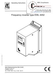
<strong>e@syDrive</strong> <strong>4425</strong>, <strong>4426.</strong>Remote controlThe function of the programmable inputs and outputs is described under Description of function A 4.4.Digital control inputsFB_IN1 ... 6opto-decoupled, Re = 10 kΩ, unwired=lowX5:1 ... 6 U_low = 0...+5 V, U_high = +13...+35 V, Ie = 2.4 mA at 24 VInput protected up to max. ± 35 V, minimum pulse width 60 msFB-24 V X6:824V-supply voltage for the digital inputsRelay switching outputsFB-Relais 1Contact type: change-over contact, max. 250 V~, 1 A, max. 30 V-, 1 AX7:1 ... 3 min. switching current 1 mA at 24V (10mA bei 10V)FB-Relais 2Contact type: change-over contact, max. 250 V~, 1 A, max. 30 V-, 1 AX8:1 ... 3 min. switching current 1 mA at 24 V (10 mA at 10 V)Analogue inputsFB-N value Ue = 0...10 V, Re = 100 kΩ, Ie = 0,1 mA bei 10 V,X6:7 unwired 0 V, input protected up to max. ± 40 VFB+10 VX6 :6FB-MasseX6:5FB-Input+FB-Input-X6:3,4Uout = 10 V +-3%, Iout = max. 25 mA,Earth reference point for FB+10 Vcurrent input 0 … 20 mAshort-circuit-proof I_k = max. 50 mAFrequency outputFB-Out-Freq simple frequency output of the inverter, keying proportion 50 %X6:2 open collector, U_max = 24V, I_max = 30 mAFB-GroundX6:1Earth reference point for frequency-outputFB-voltage outputs are related to the frequency output FB Ground.The relay outputs are originally galvanically separated._Supply module <strong>e@syDrive</strong> 4428The mains adaptor is designed for supplies to the <strong>e@syDrive</strong> <strong>4425</strong>.see GA Supply Module 4428 Mat. Nr. 1.003.1905When using a transformer, or another power pack, the secondary voltage must be provided with insulationdouble that of the mains potential. This means the converter supply voltage must be galvanically separatedfrom the mains.When using a transformer the Standard EN 61558 for double insulation must be observed.Current: max. 16 A (4426, max. 10 A (<strong>4425</strong>).8
<strong>e@syDrive</strong> <strong>4425</strong>, <strong>4426.</strong>A 1.5 Technical Data Inverter <strong>e@syDrive</strong> 4426ConfigurationOperationDisplayvia the serial interface using a standard PCB browservia an SPS-compatible remote control or using a standard PC browser(via the serial interface)lamps for operation (green) H4 and overload (yellow) H5Dimensionsapprox. 75 mm wide, 337 mm high, 215 mm deep, for switchgear housingsee also cap. B1.<strong>Operating</strong>temperature 0 ... 40°CHumidity of the air: lower than 90 % relative humidity, non-condensatingWeightapprox. 3,0 kgTests andstandardsVDE tested according to EN 61800-5-1 CSA to UL 508CEMV to EN 61800-3EMC according to EN 61800-3Ingress protection IP20 according to DIN 40050PerformanceElectricalconnectionsingle-phase max 50 V~, 50/60 Hz or max 70 V- / 14 ACurrent consumption 14 A~Output powermax. 1000 VA continuous operationOutput voltage 3 x 45 V~ at 16 AOutput current max. 16 A~ pro Phase continuous operationOutput frequency 30 ... 4000 Hz for ASM-motors (240.000 min -1 )30 ... 4000 Hz for BLDC-motors (240.000 min -1 )BrakingresistanceinternalEfficiency 93 % (at 1000 VA, cos phi motor 86 %)Motor sensorsMotor temperature sensorPTC (cold conductor): according to DIN 44081cold resistance: Rk < 550 OhmTripping resistance(warm):Ra >= 1350 ΩTripping temperature: depending on PTC 90...130°C<strong>Operating</strong> voltage: 12 V, via 4750 Ω pullup resistanceRecommendedType PTC:Siemens+Matsushita M1100 B59100-M90-A70RecommendedType KTY:Semiconductor sensor KTY84, cut-out threshold configurableHall sensor connection, motor code:Ouptutvoltage: 12 V -10%Output current: max. 100 mASignal level:active lowSwitching current: Is = 15 mApullup -resistance: internal 3 x R = 2200 Ω9
<strong>e@syDrive</strong> <strong>4425</strong>, <strong>4426.</strong>Remote controlThe function of the programmable inputs and outputs is described under Description of function A 4.4.Digital control inputsFB-In1 ... 624 V-SPS compatiblyX5:1 ... 6 U_low = 0...+5 V, U_high = +13...+35V, Ie = 2 mA bei 24 VInput protected up to max. ± 35 V, minimum pulse width 60 msFB-24V X6:824V- supply voltage for the digital inputsRelay switching outputsFB-Relais 1Contact type: change-over contact, max. 250 V~, 1A, max. 30 V-, 1 AX7:1 ... 3 min. switching current 1 mA bei 24 V (10 mA bei 10 V)FB-Relais 2Contact type: change-over contact, max. 250 V~, 1A, max. 30 V-, 1 AX8:1 ... 3 min. switching current 1 mA bei 24 V (10 mA bei 10 V)Analogue inputsFB-N_soll Ue = 0...10 V, Re = 100 kΩ, Ie = 0,1mA bei 10 V,X6:7 unwired 0 V, Input protected up to max. ± 40 VFB+10VX6 :6FB-valueX6:5FB-Input+FB-Input-X6:3,4Uout = 10 V +-3%, Iout = max. 25 mA,Earth reference point for FB+10 Vcurrent input 0 … 20 mAshort-circuit-proof I_k = max. 50 mAFrequency outputFB-Out-Freq simple frequency output of the inverter, keying proportion 50 %X6:2 open collector, U_max = 24 V, I_max = 30 mAFB-groundX6:1Earth reference point for frequency-outputFB-voltage outputs are related to the frequency output FB Ground.The relay outputs are originally galvanically separated._Supply module <strong>e@syDrive</strong> 4429The mains adaptor is designed for supplies to the <strong>e@syDrive</strong> <strong>4426.</strong>see GA Supply Module 4428 Mat. Nr. 1.003.1905When using a transformer, or another power pack, the secondary voltage must be provided with insulationdouble that of the mains potential. This means the converter supply voltage must be galvanically separatedfrom the mains.When using a transformer the Standard EN 61558 for double insulation must be observed.muss.Current: max. 16 A (4426, max. 10 A (<strong>4425</strong>).10
<strong>e@syDrive</strong> <strong>4425</strong>, <strong>4426.</strong>A 2 Scope of delivery - AccessoriesA 2.1 Scope of delivery• Frequency inverter type <strong>4425</strong> Mat.-No. 1.001.2769 (open version ) or• Frequency inverter type 4426 Mat.-No. 1.002.2514 (open version )or• Frequency inverter type <strong>4425</strong> Mat.-No. 1.001.2768 (closed version) or• Frequency inverter type 4426 Mat.-No. 1.002.2513 (closed version)• <strong>Instructions</strong> for use and assembly Mat.-No. 1.001.7140• Brief <strong>Operating</strong> <strong>Instructions</strong> Mat.-No. 1.003.1414GebrauchsanweisungUmrichter e@sy DRIVE <strong>4425</strong>/4426A 2.2 Accessories• Connection adapter for 9 pin Sub-D plug with screw connection with PC Mat. No. 1.002.2025.• -Power modul for Frequenz-Inverter Ttyp 4428 Mat. No. 1.001.2770 (closed version)• -Power modul for Frequenz-Inverter typ 4429 Mat. No. 1.002.2515 (closed version)• -Installation Assistant for 9-polar connection cable Mat. No. CD 1.003.2701• -Brief <strong>Operating</strong> <strong>Instructions</strong> Mat. No. 1.003.141411
<strong>e@syDrive</strong> <strong>4425</strong>, <strong>4426.</strong>A 3 Operational elementsH4 LED 1 Operational (green)H5 LED 2 Fault (yellow)Operation of the unit is usually carried using an SPS-compatible remote controlThe unit is configured exclusively by the special software using a standard Web browser and by means of aserial data connection (standard 9 polar sub-D cable) which communicates with the Inverters <strong>4425</strong>/<strong>4426.</strong>1212A 3.1 Rating plate 3The unit is in conformity with the requirements of the European VDE Standard.3312
<strong>e@syDrive</strong> <strong>4425</strong>, <strong>4426.</strong>A 4 Description of functionThe min. output frequency is 30 Hz (1800 min -1 )The max. output frequency is 4000 Hz (240 000 min -1 ) for ASM-motors and for DC-motors.The max. output power is 350 VA.(<strong>4425</strong>) and 1000 VA (4426).The frequency inverter Typ <strong>4425</strong>/4426is suitable for the variable-frequency control of various motors, especiallywith high frequencies of up to 4000 Hz corresponding 240 000 min - . The output voltage is set via a pulse amplitudemodulation (PAM) with 120° blocks.A 4.1 Three-phase asynchronous motor (ASM)Three-phase asynchronous motors (ASM) are controlled by means of pulse amplitude modulation (PAM). Thevoltage/frequency table serves as a basis for determining the motor voltage. Various control procedures areavailable – controlling method IR and load compensation are provided.A 4.2 Brushless DC motor without sensors (BLDC)Brushless DC motors have a pemanent magnet rotor and a fixed three-phase winding. The winding is preferablydesigned as an air-gap winding with yoke, but a grooved version similar to an ASM motor is also possible.The motor is controlled as a function of the rotor position. The rotor position is simulated by the inverter bymeasuring the e.m.f. voltage from the three part-windings. No position sensors are required. In order to permitmeasurement of the e.m.f. voltage, the motor inductance may not be too large.A 4.3 Brushless DC motor with position sensors (BLDCS)The design of this motor is identical to that of the BLDC motor described above. For position detection, however,3 additional Hall sensors are installed in the motor.A 4.4 Remote controlThe voltages at the remote control plug may be max. 60 V DC or. 25V AC according to SELV (EN50178) betrag.Exceptions are the relay connections, which are approved for max. 250 V AC.All connections are potentially isolated from the control and with respect to the protective conductor.The remote control provides a large number of programmable inputs and outputs:6 digital inputsSPS-compatible (24 V). The inputs In1 ... 6 are programmable with the parameters P110-input IN1 ...P115-input IN6 (see Section A 4.5)2 relay outputs(potential-free max. 250 V~, 30 V- / 1 A) for outputting various status signals (see parameters P120-RelaisREL1 ... P121-Relais REL2)2 analogue inputsFB-N_soll (0 ... 10V) or FB-Input+, FB-Input- (0...20 mA) for the functions of speed setpoint default and torquedefault. The programming is performed with the parameters P129-quell-AIN (see Section A 4.6)1 frequency output(open collector, max 24 V) with one times the inverter output frequency.2 auxiliary voltages+24 V (max. 100 mA) for wiring of the digital inputs In1...In6 and of the relay outputs REL1...REL2+10 V (max. 25 mA) as auxiliary supply from external potentiometers to the analogue inputs AIN1 and AIN213
<strong>e@syDrive</strong> <strong>4425</strong>, <strong>4426.</strong>Control with external voltage supplyAnaloge Eingänge / analogous inputsDA+-+10V100kX6:6X6:7X6:3X6:4AinIn+In-Eingang 0...10V (Drehzahlsollwert),speed controlEingang 0...20mA (Drehzahlsollwert),speed controlGNDX6:5GNDGNDBezugspunkt analog /common analogous24V =50mA10k10k10k10k10k10kX6:8X5:1X5:2X5:3X5:4X5:5X5:6Digitale Eingänge / digital inputs24V = aktiv / 24V = activeIn1In2In3In4In5In6X7:1X7:2X7:3NCNOComRelaisausgänge / relay outputsRelais 1 / relay 1X8:1X8:2X8:3NCNOComRelais 2 / relay 2X6:2fFrequenzausgang / frequency outputGNDX6:1GND14
<strong>e@syDrive</strong> <strong>4425</strong>, <strong>4426.</strong>Control without external voltage supplyAnaloge Eingänge / analogous inputsDA+-+10V100kX6:6X6:7X6:3X6:4Refl 10VAinIn+In-immer extern /always extern10k Eingang 0...10V(Drehzahlsollwert),speed controlEingang 0...20mA(Drehzahlsollwert),speed controlGNDX6:5GNDBezugspunkt analog /common analogous24V =50mA10k10k10k10k10k10kX6:8X5:1X5:2X5:3X5:4X5:5X5:6Digitale Eingänge / digital inputs24VIn1In2In3In4In5In6X7:1X7:2X7:3Relaisausgänge / relay outputsNCNORelais 1 / relay 1ComX8:1X8:2X8:3NCNOComRelais 2 / relay 2X6:2fFrequenzausgang / frequency outputGNDX6:1GND15
<strong>e@syDrive</strong> <strong>4425</strong>, <strong>4426.</strong>A 4.5 Motor codes via inputs IN2...IN6 to X5:In order to use IN2...IN6 for the motor codes, code P102 must be assigned to the number of the motor to beused (1...32). Additionally, the required inputs are to be set to motor code with parameters P111 – inputIN2 up toP115 – input IN6.Bit4 Bit3 Bit2 Bit1 Bit0 code value in P20 Assigned motor parameterIN2 IN6 IN5 IN4 N3 memoryL L L L L 1 M1L L L L H 2 M2L L L H L 3 M3L L L H H 4 M4L L H L L 5 M5L L H L H 6 M6L L H H L 7 M7L L H H H 8 M8L H L L L 9 M9L H L L H 10 M10L H L H L 11 M11L H L H H 12 M12L H H L L 13 M13L H H L H 14 M14L H H H L 15 M15L H H H H 16 M16H L L L L 17 M17H L L L H 18 M18H L L H L 19 M19H L L H H 20 M20H L H L L 21 M21H L H L H 22 M22H L H H L 23 M23H L H H H 24 M24H H L L L 25 M25H H L L H 26 M26H H L H L 27 M27H H L H H 28 M28H H H L L 29 M29H H H L H 30 M30H H H H L 31 M31H H H H H 32 M32L = low voltage 0..5V (contact open), H = high voltage, 24 V (contact closed)16
<strong>e@syDrive</strong> <strong>4425</strong>, <strong>4426.</strong>A 4.6 Setpoint value selectionThe frequency setpoint value (speed setpoint value) can be predetermined by various sources, and the mode ofoperation is shown in the following figure.P7 Betriebsartmode of operationP1 f_soll (Browser)BrowserP141 Eingang f_sollP141 input f_sollP142 Freigabe FFP142 release FFBrowserclosedgesperrtselektivselectivP10 f_soll_aktAnalog-Eingang AIN1 [0..10V]analogous input AIN1 [0..10 V]Umrechnung in f_sollconversion in f_sollAIN1P135 f_fern_minP136 f_fern_maxAnalog-Eingang AIN2 [0..20mA]analogous inputUmrechnung in f_sollconversion in f_sollP129 Quelle AINP129 sources AINAIN2FernbedienungRemote control00P104 Festfrequenz FF101P104 fixfreqency FF110P105 Festfrequenz FF2P105 fixfreqency FF211P106 Festfrequenz FF3P106 fixfreqency FF3Auswahl Festfrequenz (IN5/IN6)selection fixfreqency (IN5/IN6)P114 Funktion IN5 (Festfreq.)P115 Funktion IN6 (Festfreq.)P114 function IN5 (fixfreq.)P115 function IN6 (fixfreq.)Remote controlFernbedienungVerwendete Parameter:P1 f_soll (Browser)P7 Betriebsart / mode of operationP10 f_soll_aktP104 Festfrequenz FF1 / fixfrequency FF1P105 Festfrequenz FF2 / fixfrequency FF2P106 Festfrequenz FF3 / fixfrequency FF3P114 Funktion IN5 / function IN5P115 Funktion IN 6 / function IN6P129 Quelle AIN (AIN1-Spannung, AIN2-Strom ) / sources AIN /AIN1-voltage, AIN2-currentP130 Funktion AIN (AUS, Freq.Sollwert) / function AIN (out, frequency setpoint)P135 f_min AINP136 f_max AINP141 Eingang Freq.Sollwert / input frequency setpointP142 Freigabe Festfrequenz / release fixfrequencypicture: setpoint value selectionIn order to use the setpoint value of the browser in P1-f_value, the browser is set to P7-Drive. This enables thefunctions start/stop and assigned frequency to be controlled via the browser.Following a power failure, an automatic start by the installed start signal at IN1 is prevented. A flank at thestart entry is necessary.When starting via the browser, FB IN1 (P110) must be placed at OnStart/StopNetz ein kein Start möglichIN1StartStopAlternatively, you can adjust P7-Drive to “selective” ; P141-Input.f value to “browser” ; and P142-Release FF to“blocked”.17
<strong>e@syDrive</strong> <strong>4425</strong>, <strong>4426.</strong>In order to use the setpoint value from analogue input AIN1 or AIN2, set P7-Drive to “selective”; P141-Input fvalue to “remote control” ; P142-Release FF to “blocked” ; and P129 to the desired analogue input. The scale ofthe analogue inputs is carried out via “P135-f_fern_min” and “P136-f_fern_max”.To use the fixed value (fixed frequency) in P104 to P106, set P7-Drive to “selective”, as well as P142-ReleaseFF to “remote control”. Selection is effected from control inputs IN5 and IN6. If both inputs are on OV, then thesetpoint value from P1 – f value or from analogue input AIN1/AIN2 is used – depending on the condition ofP141-Input.f value. This allows the use of up to four fixed frequencies. The following table illustrates theassignment of the input combinations.input IN5 input IN6 active setpoint valueL L P1-f_soll oder AIN1 (1)L H P104-FestfreqFF1H L P105-FestfreqFF2H H P106-FestfreqFF3L = low voltage (0V), H = high voltage (24V)Note (1): with this combination the setpoint value in P141-Input. f is selected, i.e. P1- f value or from analogueinput AIN1 or AIN2 (dependent on P129).A 4.7 Emergency motor stop at Power failureWith parameter P58-emerg.stop, the inverter can be set so that a running motor is automatically braked inthe event of failure or if the mains voltage falls below ones threshold value. The inverter supplies itself from themotor voltage still present, and braking is performed with maximum power of the brake resistance. The motorgenerally cannot be braked to a stop since the motor voltage is no longer sufficient for supplying the inverter.If an emergency stop occurs as a result of a brief drop in mains voltage, the motor is braked to a stop. In orderto start the motor again, the operator must first input a stop command followed by a start command.A 4.8 Counterclockwise operationIn standard operation, the motor, spindel operates clockwise. With one of the parameters P111-input IN2 toP113-input IN4, a digital input can be configured for counterclockwise operation. If the corresponding inputis supplied with voltage, the direction of rotation changes to counterclockwise. If the direction of rotation isswitched while the motor is running, the motor is first braked before it is powered up again in the altered directionof rotation.18
<strong>e@syDrive</strong> <strong>4425</strong>, <strong>4426.</strong>A 4.9 Wiring diagram0X7:1X7:2X7:3X8:1X8:2X8:3NCNOCOMNCNOCOMWVUWVUmax. 70V DCmax. 49V AC 50/60Hz19
10 mm10 mmØ 6 mm<strong>e@syDrive</strong> <strong>4425</strong>, <strong>4426.</strong>B 1 Assembly and InstallationBefore the installation and commissioning of this device, please read the safety and warning informationunder Section A1 carefully.B 1.1 AssemblyFrequency inverter type <strong>4425</strong>, 4426 designed for mounting in cabinet:Use 4 screws for mounting on switch board.Ensure proper electrical connection to protective conductor.Information on coolingThe inverter is cooled by an integral fan. To ensure effective cooling, at least the following clearances mustbe maintained around the inverter:End surfaces: 50 mmLongitudinal: 10 mmInstallation frequency inverter <strong>e@syDrive</strong> <strong>4425</strong>10 mm75 mm10 mm68 mmØ 5,5 mm30 mm50 mm7,5 mm50 mm238 mm150 mm257,5 mm285 mm310 mm50 mm215 mm50 mm20
10 mm10 mmØ 6 mm<strong>e@syDrive</strong> <strong>4425</strong>, <strong>4426.</strong>Installation frequency inverter <strong>e@syDrive</strong> 442610 mm75 mm10 mm68 mmØ 5,5 mm30 mm50 mm7,5 mm50 mm238 mm150 mm287,5 mm312,5 mm337 mm50 mm215 mm50 mmB 1.2 Electrical InstallationWhen installing the inverter, the applicable safety regulations must be observed. Cut-out devices forpreventing unexpected start-up must be provided. A device for the electrical isolation of the inverter mustbe provided unless a mains cable with a plug is used. The Power modul must be provided with 16 A power cutoutswith tripping characteristic B.B 1.3 Wiring guidelines for compliance with the EMC standardsThe inverter was tested according to EMC product standard EN 61800-3 (variable-speed electrical drives).■ The above-mentioned EMC product standard can be complied with only by means of shielded motor andcontrol cables. It should be ensured that the cable shields rest over a large area of the inverter housing and aresurrounded by the cable clips. A shielded mains cable is not required.■ The control cables must be laid separately from (not parallel with) mains and motor cables. Shielded cablesand metallized plug housings should be used.■ All devices in the mounting cabinet should be connected over a large area to a common earthing point viashort earthing cables.■ On installation of the inverter, valid safety provisions may on no account be infringed.21
<strong>e@syDrive</strong> <strong>4425</strong>, <strong>4426.</strong>B 1.4 Electrical connectionsAccess to the electrical connectionsConnection area for <strong>e@syDrive</strong> <strong>4425</strong>, 4426For inverter <strong>4425</strong>, 4426 the supply cable is connected to “In sek.” 2 and “PE” 1. The cable shield is to be neatlyclamped under the traction relief.When the closed-cover version is selected, ensure that both covers are conductively well connected together (eithervia the switchbox or other appropriate means).1In sek. PE PE222
<strong>e@syDrive</strong> <strong>4425</strong>, <strong>4426.</strong>Motor connectionsThe motor is connected to U,V,W 1.It is possible to connect vibration sensors to “Hall 1,2, 3“ 4, and their electrical supply to “12V” or “GND” 3.A motor-temperature sensor is attached to “PTC” and “GND” 2.1U V W2GndPTC312VHall3 2 1Gnd43plug type: spring-clip (max 2,5 mm2 / AWG 12)X4: Connection Remote controlconnection of digital outputs (Relays)Com N.O. N.C. Com N.O. N.C.Relais 1 Relais 223
f<strong>e@syDrive</strong> <strong>4425</strong>, <strong>4426.</strong>connection of digital inputs, analogue inputs and frequency outputsGndIn+In-GndRefAinGnd24VIn1In2In3In4In5In624VX5: connection PC for configurationPlug type: 9-pin socket Sub-D 1, Circuit Mat.- Nr. 1.002.2025 Installation assistant see A 2.2 Accessories124
<strong>e@syDrive</strong> <strong>4425</strong>, <strong>4426.</strong>B 2 Description of the Installation Assistant <strong>e@syDrive</strong> <strong>4425</strong>/4426Apart from the two LED’s H4 Operation and H5 Fault, the inverter contains neither operating nor displayelements. The complete operation and configuration is regulated with the help of a standard Microsoft WindowsPC Web-browser (e.g. Microsoft Internet Explorer or Netscape Navigator). The browser communicates seriallywith the inverter <strong>4425</strong>/4426 via a so-called data transmission network, using a serial cable connected to theinverter. The contents of the configuration-software is stored in the inverter itself, and after selection of the IPidentification address in the browser, this is then loaded and started.The installation assistant provides all necessary pre-requisites for the programme to automatically instal thisdata transmission connection.The whole procedure is carried out automatically and installs the KaVo <strong>4425</strong>/4426 icon on the desktop. Adouble-click on this icon activates the installation software, and starts the connection to the data transmissionnetwork (see Tasks of the Installation Assistant).In the following chapters, the tasks of the Installation Assistant; the features of the individual operating systems;(Win 95, Win 98, 2000, ME, NT, XP) and their applications are explained.Connecting the Inverter <strong>4425</strong>/4426 with the serial interface (COM interface) of the PC25
<strong>e@syDrive</strong> <strong>4425</strong>, <strong>4426.</strong>B 2.1 Tasks of the Installation AssistantRecognition of the installed drive systemWhen implementing of the programme, the drive system being used is first established. Recognition of the drivesystem is necessary in order to access the special properties of the respective system in order to appropriatelycontrol the further course of the programme.Recognition of the standard browserConfiguration of the <strong>e@syDrive</strong> is carried out with the help of a Web browser and a supplementary programme(Java-Applets).Therefore it is essential that the installed browser is at a specific development status. For this reason, theInstallation Assistant investigates the installed browser and indicates if it does not meet the requirements.Discovering if the data transmission backgound is correctly installedIn order to provide a data transmission connection, the transmission background must be installed. Theprogramme set-up checks if the transmission background is available. If this is not the case, the user receives afault warning. At the same time a Windows set-up is automatically started, whereby the user can install thenecessary components.Recognition of the RAS-Version (Remote Access Service)For an automatic set-up of the data transmission connection, specific Windows functions (WIN-API) are used. Asthese are not available on older Windows versions, the installed RAS-Version is checked and, if necessary, anupdate is automatically started.Installation of the connection softwareIn order to access the <strong>e@syDrive</strong>, the software for the connection is installed via a serial cable connection(COM interface).Setting up the data transmission connectionThe data transmission connection for the configuration of the <strong>e@syDrive</strong> via the serial interface is set upautomatically. Furthermore, other adjustments specific to <strong>e@syDrive</strong> for this connection occur (no flow-control,connection rate 38400bps, IP-Address 10.0.0.1, no IP-header condensing)Installation of an icon on the desktop and in the Start menuOn completion of the installation, an icon is installed on the desktop and in the Start menu. This icon indicates aprogramme with which the data transmission connection is automatically started, and the standard browser withthe address details http:// 10.0.0.1 is called up.The Internet browser used (Microsof Internet Explorer) must be correctly configured so that the so-calledJava-Applets can be processed: Microsoft VM (virtual machine) must be activated, not SunVM!26
<strong>e@syDrive</strong> <strong>4425</strong>, <strong>4426.</strong>B 2.2 Installing the Installation Assistant in various operating systemsWindows 95With Windows 95 the minimum requirement is the version Windows 95B. The basic installation of Windows 95Bmust at least include Internet Explorer 4.01.If this is not available, inform your IT specialist!Furthermore, an update of the RAS software must be carried out. This update is started automatically by theInstallation Assistant.The standard installation of Windows95B does not include the data transmission network, which must eventuallybe installed. In this case, Windows Setup is automatically started by the setup programme.In addition, a driver for the serial connecting cable is not included as standard.This will be prepared and installed by the setup programme.After inserting the CD “Installation Assistant“ the following messages appear on the screen:- confirm with “OK“Installation of the data transmission network- confirm with “OK“- confirm with “OK“27
<strong>e@syDrive</strong> <strong>4425</strong>, <strong>4426.</strong>At “connections”, if the background is grey, double-click on “connections“ until the background turns white.- confirm with “OK“- several installations are carried out, all of which must be confirmed with “yes“.- finally, restart the computer.- open the CD compartment and close it again.Update of the RAS software being carried out- confirm with “OK“- confirm restart with “yes“- open the CD compartment and close it again.- confirm everything up to this window with “OK“- confirm restart with “yes“28
<strong>e@syDrive</strong> <strong>4425</strong>, <strong>4426.</strong>RAS update being carried out- confirm with “OK“select location of serial connecting cable- confirm with “OK”RAS modem installed- confirm with “OK”- confirm with “OK”- confirm “Reboot“After successful installation, the “<strong>e@syDrive</strong>” icon appears on the desktop29
<strong>e@syDrive</strong> <strong>4425</strong>, <strong>4426.</strong>Windows 98 / 2nd EditionWith Windows 98 normally no update is necessary, i.e. no new Internet Explorer has to be installed and it is alsonot necessary to perform an RAS update.The standard installation of Windows98 does not include the data transmission network, which must eventuallybe installed. In this case, Windows Setup is automatically started by the setup programme.The modem driver will be prepared and installed by the setup programme.After inserting the CD “Installation Assistant“ the following messages appear on the screen:- confirm with “OK”Installation of the data transmission network- confirm with “OK”- 1 This message appears only when in Windows 98 properties “connections“ has not been clicked.(for installation of “connections” - see under Win 95)- when “connections“ installed, please restartthis message appears:RAS update being carried out- confirm with “OK”select location of serial connecting cable30
<strong>e@syDrive</strong> <strong>4425</strong>, <strong>4426.</strong>- confirm with “OK”RAS modem installed- confirm with “OK”- confirm with “OK”- confirm “Reboot“After successful installation, the “<strong>e@syDrive</strong>” icon appears on the desktop31
<strong>e@syDrive</strong> <strong>4425</strong>, <strong>4426.</strong>Windows 2000Windows 2000 needs no software update. For the installation of the modem a special Windows 2000 driver isused. An automatic start for the data transmission connection follows with the programme rasdial.exe.After inserting the CD “Installation Assistant“ the following messages appear on the screen:- confirm with “OK- confirm with “OK- confirm “Reboot“After successful installation, the “<strong>e@syDrive</strong>” icon appears on the desktop32
<strong>e@syDrive</strong> <strong>4425</strong>, <strong>4426.</strong>Windows MEWith Windows ME no update of the software for Internet Explorer or RAS software is necessary. The modemdriver provided by the setup is also used here for the serial connection. The version of the modem driver is thesame for operating systems Win 9x / ME.After inserting the CD “Installation Assistant“ the following messages appear on the screen:- confirm with “OK”- confirm with “OK”select location for the connection cableRAS- Modem installed- confirm with “OK”33
<strong>e@syDrive</strong> <strong>4425</strong>, <strong>4426.</strong>- confirm with “OK”- confirm “Reboot“after successful installation, the “<strong>e@syDrive</strong>“ icon appears on the desktop.34
<strong>e@syDrive</strong> <strong>4425</strong>, <strong>4426.</strong>Windows NTIn order to run the setup progamme with Windows NT, Service Pack 3 or higher must be installed. In addition, itcould be that the Internet Explorer has to be updated to a newer version (4.01 >) .The standard installation of Windows NT does not include the data transmission network, which must eventuallybe installed. In this case, Data Transmission Setup is automatically started by the setup programme.After inserting the CD “Installation Assistant“ the following messages appear on the screen:- confirm with “OK”Installation of the data transmission network- confirm with “OK”- confirm with “OK”RAS modem installed35
<strong>e@syDrive</strong> <strong>4425</strong>, <strong>4426.</strong>- confirm with “OK”- confirm with “OK”- Where Windows is installed as standard, the following message appears- contact your IT specialist (update with Installation CD Windows NT 4)- afterwards, restart- confirm with “OK”36
<strong>e@syDrive</strong> <strong>4425</strong>, <strong>4426.</strong>- confirm with “OK”- confirm “Reboot“After successful installation the “<strong>e@syDrive</strong>“ icon appears on the desktop.37
<strong>e@syDrive</strong> <strong>4425</strong>, <strong>4426.</strong>Windows XPWindows XP needs no software update. For the installation of the modem, the Windows 2000 driver is used –this also works with Windows XP. An automatic start of the data transmission connection follows with theprogramme rasdial.exe.- confirm with “OK”- confirm with “OK”- confirm with “OK”- confirm “Reboot“After successful installation, the “<strong>e@syDrive</strong>“ icon appears on the desktop.38
<strong>e@syDrive</strong> <strong>4425</strong>, <strong>4426.</strong>B 3 <strong>Operating</strong> softwareB 3.1 LanguageAfter starting the operating software via the “<strong>e@syDrive</strong>“ icon (takes about 40 seconds), a page to select thelanguage appears:Confirm the security warning with “yes”.Entry page for language selectionBy use of the link industrie.ewl@kavo.de you can send an E-mail directly to KaVo Industrial Drive Systems(providing this option is configured in the browser).A click on http://www.kavo-drives.com leads you directly to the home page of KaVo Industrial Drive Systems.Clicking on one of the flags to select the language calls up the Basic Parameters page.39
<strong>e@syDrive</strong> <strong>4425</strong>, <strong>4426.</strong>B 3.2 Basic parametersThe basic parameters page provides the most important operating and display valuesThe individual parameters are fully described in Chapter B 4.6.Additional operating windows :- B 3.1 Language- B 3.3 Help data- B 3.4 Display values- B 3.5 Remote control- B 3.6 Motor parameters- B 3.7 U/F Table- B 3.8 Motor-control parameters- B 3.9 Special programmesB 3.3 Help dataFor each page there is help data, which is activated by clicking on the “Help“ button.To go back to the previous page, click on “Return“40
<strong>e@syDrive</strong> <strong>4425</strong>, <strong>4426.</strong>B 3.4 Window – display valuesOn this page, the most important operational values are available online (with approx. 1 Hz) – accumulatedfaults, running times, as well as customer-specified nominal values. Via the “Information” button, a description ofthe fault can be called up.B 3.5 Window – Remote controlIn this window the SPS-compatible remote control interface can be configured.41
<strong>e@syDrive</strong> <strong>4425</strong>, <strong>4426.</strong>B 3.6 Window - Motor parametersThe displayed parameters will change according to the choice of motor connected (parameters for P90 typemotor)In accordance with B 4 Configuration, 32 motor-parameter sets can be stored in memory (M1…M32).The following functions can be called up :Motor-parameters M1 …M32 loadMotor-parameters M1 ...M32 storeMotor-parameters M1 ...M32 deleteLoad factory settingLoad KaVo Motor-parametersB 3.7 U/f-TabelleWhen an asynchronous motor is configured , the details can be entered in the U/f Table window and visuallycontrolled.42
<strong>e@syDrive</strong> <strong>4425</strong>, <strong>4426.</strong>B 3.8 Motor-control parametersThe motor-control parameters are available in a window unterlay:B 3.9 Window – Special programmesSpecial programmes windowTest of the remote control interfaceRe-setting parameters to factory settingsASS (After-Sales Service) functions43
<strong>e@syDrive</strong> <strong>4425</strong>, <strong>4426.</strong>B 4 ConfigurationAll inverter-relevant data are accessible in the form of parameters P1 ... P150.The configuration is carried out exclusively via the PC-Browser software (see B 4).Basic parametersHigher parameters, upon which further adjustments are dependent (P1 .. P9) (speed values, displayadjustments, operating language, mode of operation ...)Display valuesPure display values which cannot be changed (P10 ... P39) (voltage, current and frequency values)Motor operating parametersMotor-specific parameters for adapting the motor to the inverters (P41 ... P99)Device parametersInverter-specific parameters which can be changed (P100 ... P150)If a parameter cannot be changed (e.g. pure display values), an eye symbol (oo) appears in the first position ofthe second line in the LCD display H1. This also applies to parameters which can be changed only when themotor is stationary.If a parameter is not used, depending on the mode or other parameters, it is faded out. It is thus not displayedand also cannot be changed.Speicher für WerkseinstellungMemory for factory settingDiese Parameterkönnen über dieBrowser-Bedienungangezeigt und verändertwerden,außerdem werdensie für die MotorsteuerungundRegelung benutztThese parameterscan be displayedand changed bythe control panel;they are also usedfor motor controland regulationParameterspeicherParameter memoryP1P3....P38P40.........P96P100....P136P150Parameter resetMotorparameter ladenRecall motor parameterMotorparameter speichernStore motor parameterMotorparameter Werkseinstellungmotor parameter factory settingKaVo Typ(e) xxxxP1..P38P41.....P96P100..P137P150Speicher für MotorparameterMemory for motor parametersM1...M32Motorparameter für vordefinierte SpindelnMotor parameters for predefined spindlesautomatische SpeicherungAutomatic storageautom. Laden bei Netz einAutomatic recall at mains onKaVoTyp(e)4015EEPROMnichtflüchtigerSpeicherNonvolatilememory44
<strong>e@syDrive</strong> <strong>4425</strong>, <strong>4426.</strong>B 4.1 Special functionsUnder special functions, it is possible to establish the default state and to select various utility and test programswhich serve as troubleshooting programs and repair aids for the customer and the Technical Customer Service(TKD).B 4.2 Aktor-sensor TestThis test serves to to check the function of the remote control and the internal signal.Switch the inverter to mode “no motor“. Click to delete the warning.Temperature sensors, radiator und input voltage UR provide additional information on the condition of theinverter.Aktor-Sensor-Test45
<strong>e@syDrive</strong> <strong>4425</strong>, <strong>4426.</strong>B 4.3 Complete parameter structureThe parameter structure portrays all the properties of the inverter.This reproduction is helpful for configuration and optimizing procedures.B 4.4 Factory settingThis function adjusts all parameters P1 … P150 to the original factory settings. After confirming the securityquestion with OK " , the procedure is implemented. Motor-parameters stored in memory M1 ... M32 are notaffected.B 4.5 Technical ServiceVarious test programmes for Technical Customer Service from KaVo are accommodated under this section.46
<strong>e@syDrive</strong> <strong>4425</strong>, <strong>4426.</strong>B 4.6 Parameter listThis list includes all displayable and alterable parameters.In the column Change display, the following abbreviations are used:N = not alterableS = alterable only when motor stationaryI = always alterable, even when motor runningM = display and alterability dependent on P90-motortype* = display dependent on other parametersPar. Indication Description Value range, Unit Factory ChangeNo. in display physical value setting displayBasic parameters:P1 f soll Frequenzsollwert Bedienpanel 0...4000 Hz 50 IP2 Start/stop start/stop über Browser on, off, Reset - off I*P7 <strong>Operating</strong> Selection operation PC-Browser, selectiv - selektiv SP8 Speed displ Selection Speed displayDisplay valuesin Hz, in min -1 - in Hz I PP10 f_rated_act Current frequency setpoint value 0...4000 Hz - NP11 I_limit_act Current current limit 0.5....16 A~ - NP12 f_rated_int Frequency setpoint value after integrator 0...4000 Hz - NP13 f_wr_act Actual inverter frequency 0..4000 Hz - NP14 f_motor Actual motor frequency 0...4000 Hz - NP15 V_motor Output voltage 0..40 V~ - NP16 V_DC circ Intermediate circuit voltage 0..75 V- - NP17 I_mot_app Apparent motor current 0..10 A~ - NP18 I_mot_real Real motor power 0..10 A~ - NP19 P_real Real power 0..400 W - NP20 motor code Motor coding and motor memory 1..32 - - NP25 t_action <strong>Operating</strong> hours counter inverter 0... 65000 h 0 NP26 t_reset <strong>Operating</strong> hours counter motor 0... 65000 min 0 NP30 1st error Last error - - 0 NP31 2nd error Penultimate error - - 0 NP32 3rd error Third-last error - - 0 NP33 4th error Fourth-last error - - 0 NP34 5th error Fifth-last error - - 0 NP36 Inverter Inverter type - - - NP37 SW panel Firmware version of panel - - - NP38 SW mot cont Firmware version of motor control - - - NP39 Serialno. Serial number of Inverter - - - NP40 PC SW Ver. SW-Version of the PC operation - - - Nmotor-parameters:motor-operating valuesP41 f_mot_min Min. motor frequency 30... 100... 4000 Hz 50 S MP42 f_mot_max Max. motor frequency f_mot_nom, 100...4000 Hz P91 SP43 U_mot_max Max. motor voltage phase-phase U_mot_nenn, 1 ...50.00 V~ P92 SP44 I_limit Current limitation (phase current) 0,5...16 A~ 1,5*P93 IP46 t_rise Ramp time for run-up 0,5... 400 s 5 IP47 t_fall Ramp time for fall-down 0,5... 400 s 5 IP48 t_stop Ramp time for stop DC-brake,t_down,0,5..400 s P47 I*P50 Motor start Start option, catch circuit off, main-on, always - always I MP51 t_start Start time for microstep operation without ramp, 0,5 ... 100 s without ramp I MP52 I_start Startup current microstep oper. BLDC 0,1 ... 16 A~ 0,1 I P M *P53 f_start Startup frequency microstep operation 1 ... 30 Hz 8 S MP54 t_off Inverter switch-off time, startup 200 ... 1000 µs 330 S MP55 t_DC_brake DC brake time DC brake Aus, 0,1... 120 s Aus I MP56 I_DC_brake DC brake current DC brake 0,1 ... 10 A- 1 I M *P57 I_DC_stop DC stop current (at stop) Aus, 0,1 ... 3 A- Aus IP58 emerg. stop Select emergency stop at mains failure inactive, on at mains failure - inaktiv I47
<strong>e@syDrive</strong> <strong>4425</strong>, <strong>4426.</strong>Par. Indication Description Value range, Unit - Factory- ChangeNo. in display physical value setting displayU/f characteristic (ASM motor)P60 U_boost Startup voltage at f=0 3%U_nom, 1...50 V~ 3%U_nom I MP61 f1 1st characteristic point frequency f_nom, 30... 4000 Hz f_nom I MP62 U1 1st characteristic point voltage U_nom , 1... 50 V~ U_nom I MP63 f2 2nd characteristic point frequency f_nom, 30... 4000 Hz f_nom I MP64 U2 2nd characteristic point voltage U_nom, 1... 50 V~ U_nom I MP65 f3 3rd characteristic point frequency f_nom, 30... 000 Hz f_nom I MP66 U3 3rd characteristic point voltage U_nom, 1... 50 V~ U_nom I MControlP70 control Control principle speed control U/f,I*R - U/f-Tab. I MP71 I*R factor I*R compensation gain factor off, 0,1 ... 10 V/A off I M *P72 loadcomp Load compensation gain factor of, 0,1 ... 40 %/A~ off I M *P73 komp-t_filt I*R and load compensation. Filter time 1 ... 1000 ms 20 I M *P77 I-limtr-KP Current limitation P-component 2 ... 200 % 40 IP78 I-limtr-t_n Current limitation I-component reset time 1 ... 999, without I-part ms 2 IP79 U-contr-KP Voltage control V_WR P-component 5...100 % 20 IP80 U-contr-t_n Voltage control I-component reset time 5 ... 999, without I-part ms 2 IMonitoringP85 motor prot. Monitoring motor temperature off, PTC, KTY - PTC IP86 R_protect Resistance value for sensor KTY 500...4000 W 1200 I *Rated motor data (according to rating plate)P90 motortype Motor design no,ASM, BLDC, BLDCS -no motor SP91 f_mot_nom Rated motor frequency 30 ... 4000 Hz 100 SP92 U_mot_nom Rated motor voltage 0 ... 50 V~ 6 SP93 I_mot_nom Rated motor current 0,5 ... 16 A~ 1,0 SP94 cos phi Cosine phi at nominal load 20 ... 100 % 85 SP96 no.of poles Number of poles 2, 4, 6, 8 - 2 S:Device parameters:ext. brake resistanceP102 motorcoding Motor coding, number of motors off, 2...32 motors off SFestfrequenzenP104 fixfreq.FF1 Fixed frequency FF1 (select with IN3,IN4) 30 ... 4000 Hz 100 IP105 fixfreq.FF2 Fixed frequency FF2 30 ... 4000 Hz 100 IP106 fixfreq.FF3 Fixed frequency FF3 30 ... 4000 Hz 100 IFernbedienung:P110 input IN1 Function digital input IN1 off, start/stop, stop - off SP111 input IN2 Function digital input IN2 off, Start pulse, reset, links,motor code off SP112 input IN3 Function digital input IN3 off, reset, left, motor code - off SP113 input IN4 Function digital input IN4 off, reset, left,motor code- off SP114 input IN5 Function digital input IN5 off, reset, left,motor code, FF - off SP115 input IN6 Function digital input IN6 off, reset, left,motor code, FF - off SP120 relay REL1 Function relay output REL1 off, various status signals - f_rated IP121 relay REL2 Function relay output REL2 off, various status signals - overload IP125 I_warning var. current limit for relay output 0,4...12 A~ 0,4 IP129 Source AIN1 Source for analog input AIN1 U (0...10 V), I(0...20 mA) -V (0...10V) SP135 f_rem_min min. rated freq. of analogue input 0.. 4000 Hz 30 IP136 f_rem_max max. rated freq. of analogue input 0.. 4000 Hz 4000 IP137 f_stop_ana Stop via analogue signal off,1... 4000 Hz Aus IP140 Start on input motor start Browser, remote control - AIN1 IP141 on_f_soll input Frequenzsollwert Browser, AIN - AIN1 IP142 release ff release fixed frequency stoped, on - stoped IP146 direction direction right, left, remode control - rechts IP150 End End mark- -48
<strong>e@syDrive</strong> <strong>4425</strong>, <strong>4426.</strong>Description of the individual parametersB 4.7 Basic parametersP1-f_ratedRated frequency value (speed preselection) for the motor (input on control panel).By means of parameter P8-speed displ, this parameter can be changed from frequency display to speeddisplay. The number of motor poles P96-no. of poles is taken into account. Here, only values betweenthe min. frequency P41-f-mot-min and the max. frequency P42-f-mot-max can be set.Minimum value: 30 HzMaximum value: 4000 HzFactory setting: 50 HzP2-Start_StopCondition start/stop or reset via browser.Values: on, off, resetP7-Type of operationSelection of the source from which the inverter is to be operated with start/stop, setpoint speed value and torquelimitation. The digital and analogue output values are always output independently of the setting.Values: PC-browser- _ - Operation occurs via the browser softwareSelective. _- The inputs for start/stop, speed value and current limitations canbe selectively chosen separate over parameters P140 ... P142Factory setting: Remote controlP8-Speed displSelection of the display for rated and actual motor speeds, in Hz or in min -1 , the conversion of the frequency intothe speed is performed by the following formula:Speed = frequency * 60 / number of poles/2 of the motor (P96-no. of poles).Values :Factory setting:in Hz - the display is in Hzin min -1 - the display is in min -1 (revolutions per minute)in HzB 4.8 Display valueP10-f_soll_akt (display value)The valid rated speed value can originate from various sources depending on configuration (panel, remote controlanalogue input, remote control fixed frequency input). The currently valid value, i.e. the value transmitted tothe motor control, is displayed for the user via parameter P10.By means of parameter P8-speed display, this parameter can be changed from frequency display tospeed display, the number of motor poles P96-no. of poles being taken into account.P11-I_limit_akt (display value)The valid torque limitation may originate from P44-I_limit. The currently valid value is displayed for the uservia the parameter P11.49
<strong>e@syDrive</strong> <strong>4425</strong>, <strong>4426.</strong>P13-f_wr_ist (display value)f_out_is the current output frequency of the inverter (inverter frequency).P14-f_motor (display value)f_motor is the current motor frequency ,is the same as the output frequency (P13-f_out_act).By means of parameter P8-speed displ, this parameter can be changed from frequency display to speeddisplay, the number of motor poles P96-no. of poles being taken into account.P15-U_motor (display value)U_motor is the current motor voltage between two phases.P16-U_DC_circ (display value)U_DC_circ is the current intermediate circuit voltage.P17-I_mot_app (display value)I_mot_app is the current apparent motor voltage in phase U.P18-I_mot_real (display value)I_mot_real is the current real motor current in a phase.P19-P_real (display value)P_real is the current inverter output power, corresponding to the real power consumed by the motor.P20-motor code (display value)the currently used motor parameter memory M1...M32 is displayed. f the parameters from the memory havebeen changed, the display of the memory is not present.P25-t_action (display value)P25-t_action shows the total operating hours of the device in hours.The value is read in from the EEPROM.P26-t_reset (display value)P26-t_reset shows the operating hours of the motor.The value is read in from the EEPROM.P30-1st error (display value)1st error shows the error number of the last error which occurred.The value is read in from the EEPROM.P31-2nd error (display value)2nd error shows the error number of the penultimate error which occurred.The value is read in from the EEPROM.P32-3rd error (display value)3rd error shows the error number of the third-last error which occurred.The value is read in from the EEPROM.P33-4th error (display value)4th error shows the error number of the fourth-last error which occurred.The value is read in from the EEPROM.P34-5th error (display value)5th error shows the error number of the fifth-last error which occurred.The value is read in from the EEPROM.P36-Inverter (display value)Inverter shows the inverter type ((<strong>e@syDrive</strong> z.B. <strong>4425</strong>).P37-SW panel (display value)SW panel shows the software version and the date of the operating firmware.50
<strong>e@syDrive</strong> <strong>4425</strong>, <strong>4426.</strong>P38-HW Version (display value)HW Version shows the Hardware-version of the inverter.P39-Serialnumber (display value)Serialnumber shows the Ser. No of the inverter.P40-SW Version PC-operation (display value)SW Version PC-operation shows the Software-version of PC-Browser-configurations software.B 4.8 Motor operating valuesThese parameter values are displayed depending on the chosen motor type. The assignment to the individualmotor types is shown in square brackets.P41-f_mot_min [ASM, -, -]Absolutely minimum inverter frequency, set internally to 0 in the case of BLDC and BLDCS motors. In ASMmotor, serves for establishing the lower limit of the inverter frequency.Minimum value: 30 HzMaximum value: 100 HzFactory setting: 50 HzP42-f_mot_max [ASM, BLDC, BLDCS]Absolutely maximum inverter frequency. The output frequency of the inverter is limited to this value to protect themotor.This value is set to the maximum rated frequency in the case of ASM motors; in the case of BLDC and BLDCSmotors, this value should be set about 10% higher than the maximum rated frequency. In addition, this parametermust be set larger than P41_f_mot_minSpecific values: [100] f_mot_nom-f_mot_max is taken from the nominal motor frequency P91-f_mot_nomMinimum value: 101 HzMaximum value: 4000 Hz; 2000Hz at BLDC-MotorFactory setting: [100] f_mot_nom (see P91)P43-V_mot_max [ASM, BLDC, BLDCS]Maximum motor voltage between two phases, serves for protecting the motor from excessively high voltages.The inverter output voltage is limited to this value.Specific values: [0] V_mot_nom- V_mot_max is taken from the nominal motor voltage P92-V_mot_nomMinimum value: 1 VMaximum value: 50 VWerkseinstellung: U_mot_nom (see P92)P44-I_limit [ASM, BLDC, BLDCS]Limitation of phase current for normal motor running. The inverter limits the output current to I_limit.The stop current (P57-I_DC_stop) and, in the case of the BLDC motor, the startup current (P52-I_start)are unaffected by this.Specific values: [0.4] 1.5*I_nom - I_limit is set to 1.5 times the nominal motor current from P93-I_mot_nom.Minimum value: 0.5 AMaximum value: 16 AFactory setting: [0.4] 1.5*I_nom (see P93-I_mot_nom)P46-t_rise [ASM, BLDC, BLDCS]Rise time of frequency 0 to P42-f_mot_maxThe rise time is effective at motor start and in the case of changes of nominal frequency. If the rise time is settoo small, the motor current increases up to the current limit P44-I_limit, thus automatically increasing therise time.Minimum value: 0.5 secMaximum value: 400 secFactory setting: 5 sec51
<strong>e@syDrive</strong> <strong>4425</strong>, <strong>4426.</strong>P47-t_fall [ASM, BLDC, BLDCS]Delay from P42-f_mot_max to frequency 0.The delay is effective in the case of changes of nominal frequency and in the case of a motor stop only ifP48-t_stop is set to t_fall.Minimum value: 0.5 secMaximum value: 400 secFactory setting: 5 secP48-t_stop [ASM, BLDC, BLDCS]Stop delay time from P42-f_mot_max to frequency 0. The inverter reduces its frequency after the specifiedramp, and the motor operates as a generator. The rotational energy is converted into heat in the brake resistance.The stop time is effective only at a motor stop, after which DC braking is also performed (seeP55-t_DC_brake and P56-I_DC_brake).If t_stop is set too short, the inverter limits the generator current to the value of P44-I_limit and theactual stop time of the motor automatically increases but vibrations may occur during the braking process.Specific values: DC-brake [ASM, -, -]- At stop, the system switches directly to DC brake, there is no generator braking and the totalrotational energy is converted into heat in the rotor.t_fall- t_stop is set internally as the delay (P47-t_fall).Minimum value: 0.5 secMaximum value: 400 secFactory settting: t_fall (see P47-t_fall)P50-motor start [ASM]Motor start influences the start behaviour of the ASM motors. The catch circuit prevents an overcurrent if theinverter is switched to the running motor. The inverter starts at the maximum motor frequencyP42-f_mot_max and reduces its frequency until the inverter frequency has adapted to the motor frequency.This process takes not more than 1 second.Values: Normal-Normal motor start from the frequency P41-f_mot_min, no catch circuit.Catch power on- The catch circuit is active only when the inverter knows nothing about the actual motorspeed, for example after power on and reset, unless a speed sensor is used. If the motor wasbraked via the generator brake, the next motor start takes place without a catch circuit. If themotor is braked only via the DC brake (P48-t_stop = DC-brake), the catch circuit isactive at every motor start.Catch always- Catch circuit active at every motor startFactory setting: NormalP51-t_start [-, BLDC, -]Startup time for microstep startup in BLDC motor from 0 Hz to P53-f_start.With t_start > 0.5 sec sind, P52-I_start and P53-f_start must also be input.In the case of the microstep startup, the BLDC motor is operated as a synchronous motor with constant current(P52-I_start) . The output frequency is slowly increased from 0 to the start frequency (P53-f_start),after which the system switches to controlled motor running with e.m.f. measurement. In the case of small centrifugalmasses, the start ramp can be switched off or shorter times set. In the case of larger centrifugal masses,longer times should be set.Specific values: [0.4] without ramp - microstep startup ramp switched offMinimum value: 0.5 sec - start up with microstep startup rampMaximum value:Factory setting:100 sec[0.4] without rampP52-I_start [-, BLDC, -]Startup current for microstep startup, can be selected only if P51-t_start > 0. Low currents should be setfor a soft and quiet start and higher currents for fast start and larger centrifugal masses.Minimum value: 0.1 AMaximum value: 16 AFactory setting: 0.1 A52
<strong>e@syDrive</strong> <strong>4425</strong>, <strong>4426.</strong>P53-f_start [-, BLDC, -]Startup frequency for microstep startup. If P51-t_start is set to [0.4] without ramp, the motor start beginsat the frequency f_start; if a ramp time is set in P51-t_start, the startup begins at frequency 0 and is slowlyincreased up to f_start. On reaching the start frequency, the microstep startup is terminated. If the motor doesnot start up reliably, f_start should be increased.Minimum value: 1 HzMaximum value: 30 HzFactory setting: 8 HzP54-t_off [-, BLDC, -]Switch-off time of the inverter.In the microstep startup, the inverter is repeatedly switched off briefly in a cyclic manner in order to measure thee.m.f. voltage of the BLDC motor; this is used for detecting the position of the rotor at low speeds. In the case oflarger inductances of the motor winding, longer times should be set.Setting rule: If the BLDC motor starts up poorly or synchronizes poorly with the motor, longer times should beset; it may also be necessary to increase the startup frequency in P53-f_start.Minimum value: 200 µsMaximum value: 1000 µsFactory setting: 330 µsP55-t_DC_brake [ASM, -, -]Time for DC brake in ASM motor,0 = no DC brake. If this parameter is set to values > 0, P56-I_DC_brake should also be set.Specific values: [0] DC-brake off - There is no DC brakingMinimum value: 0.1 secMaximum value: 120 secFactory setting: DC- brake offP56-I_DC_brake [ASM, -, -]Current for DC brake in ASM motor, displayed only if P55-t_DC_brake is not set to off.Minimum value: 0.1 AMaximum value: 10 AFactory setting: 1 AP57-I_DC_stop [ASM, BLDC, BLDCS]Stop current, this current flows in the stopped motor through 2 phases; the 3rd motor phase is currentless andthe motor is thus braked (ASM motor) or is kept in a defined position (BLDC or BLDCS motor).Specific values: Off - With stopped motor, no stop current is outputMinimum value: 0.1 AMaximum value: 3 AFactory setting: OffP58-emerg. stop [ASM, BLDC, BLDCS]Parameter influences the behaviour on mains failure.Values:off- At mains failure, the motor runs out freely and there is no braking.on at mains off- The motor is braked with maximum power of the brake resistance as long as the invertercan still supply itself from the motor voltage.Factory setting: inactive53
<strong>e@syDrive</strong> <strong>4425</strong>, <strong>4426.</strong>B 4.10 Motor U/f-characteristicThe voltage/frequency table describes the key points of the motor voltage at specific frequencies for the ASMmotor.With the factory setting, characteristic points KP1... KP3 are set to the nominal frequency and the nominal voltageof the motor.With input from the table, the following must be noted:■ The frequencies must be equal or must increase in the sequence f1, f2 and f3.(P61-f1
<strong>e@syDrive</strong> <strong>4425</strong>, <strong>4426.</strong>P65-f3 [ASM, - -]U/f-characteristic: Frequency of characteristic point KP3Specific values: f_nom- the value of the rated motor frequency from P91-f_mot_nom is usedMinimum value: 30 HzMaximum value: 4000 Hz;Factory setting: f_nomP66-V3 [ASM, - -]U/f-characterstic: Voltage of characteristic point KP3Specific values: V_nom- the value of the rated motor voltage from P92-V_mot_nom is usedMinimum value: 1 VMaximum value: 60 VFactory setting: V_nomB 4.11 ControlP70-control [ASM, -, -]Selection of the speed control for ASM motorsValues: U/f table- Voltage control via U/f table, no rise-I*R-load-comp.- I*R and load compensation, the motor voltage is adapted as a function of the load. Theparameters P71-I*R-factor, P72-loadcomp and P73-comp-t_filt should be set.Factory setting: U/f tableP71-I*R-factor [ASM, -, -]Factor of the I*R compensation, the inverter output voltage is adapted as a function of the motor load.The aim of the I*R compensation is to keep the magnetic flux in the motor constant. The I*R compensation iseffective in particular at low speeds or low voltages, and the speeds decrease less sharply under load. The I*Rfactor corresponds to the ohmic resistance of the motor, measured between two motor cables.∆U = P71-I*R-factor * (P18-I_mot_real - (P93-I_mot_nom * P94-cos phi)V_mot = U_table + ∆UU_table corresponds to the U/f table voltage, calculated from the values P60...P66Specific values: off - I*R compensation switched offMinimum value: 0.1 V/A (slight rise)Maximum value: 10 V/AFactory setting: offP72-Loadkomp [ASM, -, -]Factor of the load compensation, the inverter output voltage is adapted as a function of the motor load.With the load compensation, it is possible to ensure that the motor consumes only little current during idling(little heating up) but that the magnetization current is appropriately increased under load. This makes it possibleto reduce the heating up of the motor, and the speed decrease in the load is smaller. The load compensation isapplied in particular at medium and high speeds or voltages and supplements the I*R compensation.∆U = U_table * P72-Loadkomp * (P18-I_mot real - (P93-I_mot_nom * P94-cos phi)V_mot = U table + ∆UU_table corresponds to the U/f table voltage, calculated from the values P60...P66Specific values: off - Load compensation switched offMinimum value: 0.1 %/A (slight rise)Maximum value: 40 %/A (very sharp rise)Factory setting: offP73-komp-t_filt [ASM, -, -]Filter time of the I*R and load compensationThis makes it possible to influence the rapidity of the I*R and load compensation. If the motor tends to vibrateunder load, higher values should be set.Minimum value: 1 msMaximum value: 1000 msFactory setting: 20 ms55
<strong>e@syDrive</strong> <strong>4425</strong>, <strong>4426.</strong>P77-I-limtr-KP [ASM, BLDC, BLDCS]Only in special cases should this parameter be changed from the factory setting.P77-I-limtr-KP influences the control (PI) for the motor current limitation, it being possible to set the gain(proportional part) here.Minimum value: 2 %Maximum value: 200 %Factory setting: 40 %P78-I-limtr-t_n [ASM, BLDC, BLDCS]Only in special cases should this parameter be changed from the factory setting.P78-I-limtr-t_n influences the control (PI) for the motor current limitation, it being possible to set thereset time (I-part) here. Longer times make the control slower. If the times are too short, the current controltends to oscillate.Specific values: without I-part - I-part is switched offMinimum value: 1 msMaximum value: 999 msFactory setting: 10 msP79-V-contr-KP [ASM, BLDC, BLDCS]Only in special cases should this parameter be changed from the factory setting.P79-V-contr-KP influences the control (PI) for the internal intermediate circuit voltage, it being possible toset the gain (proportional part) here. The motor voltage is generated from the intermediate circuit voltage by theinverter.Minimum value: 5 %Maximum value: 100 %Factory setting: 20 %P80-V-contr-t_n [ASM, BLDC, BLDCS]Only in special cases should this parameter be changed from the factory setting.P80-V-contr-t_n influences the control (PI) for the internal intermediate circuit voltage, it being possible toset the reset time (integral part) here. Longer times make the control slower.Specific values: without I-part - I-part is switched offMinimum value: 1 msMaximum value: 1000 msFactory setting: 2 ms56
<strong>e@syDrive</strong> <strong>4425</strong>, <strong>4426.</strong>P82-N-contr-t_n [ASM, BLDC, BLDCS]This parameter influences the control (PID) for the motor speed, it being possible to set the reset time(integral part) here. Shorter times make the control faster and longer times make it slower.Specific values: without I-part - I-part is switched offMinimum value: 5 msMaximum value: 999 msFactory setting: 200 msP83-N-contr-t_v [ASM, BLDC, BLDCS]This parameter influences the control (PID) for the motor speed, it being possible to set the derivative time(D-part) here. Longer times make the control faster and shorter times make it slower.Specific values: [0] without D-part - D-part switched offMinimum value: 1 msMaximum value: 300 msFactory setting: 8 msP84-N-contr-t_fil [ASM, BLDC, BLDCS]This parameter influences the control (PID) for the motor speed, it being possible to set the filter before theD-part here. The filter makes the D-part smoother and slightly slower. In the case of longer times, the tendencyof the D-part to oscillate is damped.Minimum value: 1 msMaximum value: 300 msFactory setting: 50 ms57
<strong>e@syDrive</strong> <strong>4425</strong>, <strong>4426.</strong>B 4.12 MonitoringP85- motor prot. [ASM, BLDC, BLDCS]The temperature of the motor can be monitored with various sensors, and the sensor type should be set here.Values: no sensor- there is no temperature monitoring of the motorsPTC- Positive temperature coefficient sensor (according to DIN 44081) with fixed switching thresholds, the cut-out temperature is determined by the sensor itself.KTY- Analogue semiconductor sensor, the swiching threshold can be set with P86-R_protectFactory setting: no sensorP86-R_protect [ASM, BLDC, BLDCS]Resistance value of the KTY sensor at the cut-out point, selectable only if P85-motor prot. is set to KTY.Minimum value: 500 ΩMaximum value: 4000 ΩFactory setting: 1200 ΩB 4.13 Nominal motor valuesIn this section, the nominal data of the connected motor should be input, this you must doing befor youadjustment the other motor parameter.The nominal data are shown on the rating plate or the data sheet.P90-motortype [ASM, BLDC, BLDCS]Input of motor design.Values: no motor - no motor definedASM - three-phase asynchronous motorBLDC - brushless DC motor without sensorsBLDCS - brushless DC motor with sensors (not in series version)Factory setting: no motorP91-f_mot_nom [ASM, BLDC, BLDCS]Nominal motor frequency according to rating plate in Hertz.Minimum value: 30 HzMaximum value: 4000 HzFactory setting: 100 HzP92-V_mot_nom [ASM, BLDC, BLDCS]Rated motor voltage according to rating plate.Minimum value: 0 VMaximum value: 50 VFactory setting: 6 VP93-I_mot_nom [ASM, BLDC, BLDCS]Rated motor current (apparent current in one phase) according to rating plate.Minimum value: 0.5 AMaximum value: 10 AFactory setting: 1.0 AP94-cos phi [ASM, BLDC, BLDCS]Motor power factor cosine phi according to rating plate.Minimum value: 20 %Maximum value: 100 %Factory setting: 85 %P96-no. of poles [ASM, BLDC, BLDCS]Number of poles in the motor. This parameter is used for speed display in min -1 .Note that the number of poles and not the number of pole pairs should be input here.Minimum value:Maximum value:Factory setting:2 poles8 poles2 poles58
<strong>e@syDrive</strong> <strong>4425</strong>, <strong>4426.</strong>B 4.14 Device parameters, remote controlP102-motorcodingBy means of this parameter, the motor coding is switched on and the number of motors used is input (seeSection A 4.5 Motor coding). A setting to 5...8 motors is possible only if no speed sensor is used, since bothfunctions share the input H1 (X7.3) (see P59-speedsensor).Only the coding inputs H1...H3 actually required are evaluated.P104-fixfreq.FF1Value of the fixed frequency FF1 which can be selected via the remote control.By means of parameter P8-speed disp, this parameter can be changed from frequency display to speeddisplay, the number of motor poles P96-no. of poles being taken into account.Minimum value: 30 HzMaximum value: 4000 HzFactory setting: 100 HzP105-fixfreq.FF2Value of fixed frequency FF 2Minimum value: 30 HzMaximum value: 4000 HzFactory setting: 100 HzP106-fixfreq.FF3Value of fixed frequency FF3Minimum value: 30 HzMaximum value: 4000 HzFactory setting: 100 HzP110-input IN1Function of the digital input IN1Values: DescriptionOFFInput has no function/Stop(24V = Start release, 0V = Stop, for Start is P111-input IN2 tobe configured to start impulseStart/Stop 24V = Start, 0V = StopP111- input IN2Function of the digital input IN2ValuesDescriptionOFFInput has no functionReverse CCW rotation (24V = CCW)ResetReset (Pulse at 24V = trigger reset)Start impulse An impulse of +24V starts the inverter, after which the input can return to OV,whereby the inverter remains in the start condition. To stop, configure input IN1with P110-input IN1 to “Stop”, and bring it to OVMotor coding Frees up the input for the motor coding, the input has the value Bit4P112- input IN3Function of the digital input IN3Values: DescriptionOFFInput has no functionReverse CCW rotation (24V = CCW)ResetReset (Pulse at 24V = trigger reset)Motor coding Frees up the input for the motor coding, the input has the value Bit059
<strong>e@syDrive</strong> <strong>4425</strong>, <strong>4426.</strong>P113- input IN4Function of the digital input IN4ValuesDescriptionOFFInput has no functionReverse CCW rotation (24V = CCW)ResetReset (Pulse at 24V = trigger reset)Motor coding Frees up the input for the motor coding, the input has the value Bit1P114- Input In5Function of the digital input IN5ValuesDescriptionOFFInput has no functionReverse CCW rotation (24V = CCW)ResetReset (Pulse at 24V = trigger reset)Motor coding Frees up the input for the motor coding, the input has the value Bit2Fixed frequency Frees up the input for the choice of the fixed frequency, the input has the value Bit1P115- Input In6Function of the digital input IN6ValuesDescriptionOFFInput has no functionReverse CCW rotation (24V = CCW)ResetReset (Pulse at 24V = trigger reset)Fixed frequency Frees up the input for the choice of the fixed frequency, the input has the value Bit0.Motor coding Frees up the input for the motor coding, the input has the value Bit3P120-relay REL1Output value of relay REL1Values: off :- no function, relay is in opened state.operation:- The inverter is ready for operation, the motor can be started.failure:- The inverter is in the error state, the motor cannot be started and a reset is required.overload:- The motor current has reached the current limit.(P17-I_mot_app >= P44-I_limit, -10% hysteresis)N_rated reached:- The actual speed of the motor has reached the rated speed(P14-f_motor = P10-f_rated_act, ±10% hysteresis).current limit- The real motor current is higher than the current warning threshold(P18-I_mot_real >= P125-I_warning, 10% hysteresis).motortemp:- The temperature sensor in the motor indicates that the temperature is too high(see P85-motor prot. and P86-R_protect).motor stands:- The motor is stationary, depending on motor type. The ASM motor: if a speed sensor ispresent, this signal becomes active after the end of the braking process, consisting of generatorbrake and DC brake (see P48-t_stop and P55-t_DC_brake). After the inverter hasbeen switched on or after a reset, the motor stands signal is inactive. If a speed sensor isconfigured with P59-speedsensor, this signal becomes active at an actual motorstoppage (f
<strong>e@syDrive</strong> <strong>4425</strong>, <strong>4426.</strong>P121- relay REL2Output value of relay REL2.Values: - see under parameter P120-relay REL1Factory setting: 3] overloadP125-I_warningValue of the variable current limit for the relay output, this can be used for detecting a specific motor load, arelay output (P120- relay REL1 ... P123- relay REL4) must be configured with the current limitfunction for this purpose. The value has no effect on the current limitation.Minimum value: 0.4 AMaximum value: 8 AFactory setting: 0.4 AP129- Source Analog AIN1Selection of the source for Ain1value:U(0...10V)- SPS-kompatibel 0...10 VI(0...20mA)- SPS-kompatibel 0...20 mAFactory setting: U(0...10V)P135-f_rem_minMinimum rated frequency for analogue rated frequency default AIN1 at V_e = 0V. This parameter is evaluatedonly if P130-analogue AIN1 is configured for rated frequency.By means of parameter P8-speed displ, this parameter can be changed from frequency display to speeddisplay, the number of poles of the motor P96-no. of poles being taken into account.Minimum value: 30 HzMaximum value: 4000 HzFactory setting: 30 HzP136-f_rem_maxMaximum rated frequency for analogue rated frequency default AIN1 at V_e = 10V. This parameter is evaluatedonly if P130-analogue AIN1 is configured for rated frequency.By means of parameter P8-speed displ, this parameter can be changed from frequency display to speeddisplay, the number of poles of the motor P96-no. of poles being taken into account.special valve: [0] f_mot_max - valve of P42-f_mot_max is used to automatically adjust to maximumfrequency of motor.Minimum value: 30 HzMaximum value: 4000 HzFactory setting: 4000 HzP137-f_stop_anaStop frequency from analogue rated frequency signal; this makes it possible to achieve an automatic motor stopwith counterclockwise rotation of the nominal value potentiometer or analogue voltage 0 V.The motor is automatically stopped if the rated frequency default at analogue input AIN1 falls below the value ofthis parameter. By means of parameter P8-speed displ, this parameter can be changed from frequencydisplay to speed display, the number of poles of the motor P8-no. of poles being taken into account.In this context, also see the parameter P135-f_rem_min and P136-f_rem_max.special Values: off - no automatic stopf_mot_min - the value from P41-f_mot_min is usedMinimum value: 30 HzMaximum value: 4000 HzFactory setting: offP140-Input StartWith this, the input for the motor start is determined. This parameter is displayed and evaluated only when P7-Operational Mode is set to Selective.Value: PC browser -start/stop is implemented via the control panel (start, nominal values)Remote control start/stop is implemented via inputs In1 and In2 of the remote control - seeP110-input IN1 and P111-input IN2.Factory setting: Remote control61
<strong>e@syDrive</strong> <strong>4425</strong>, <strong>4426.</strong>P141- Input f_valueWith this, the input for the frequency nominal value is determined. This parameter is displayed and evaluatedonly when P7-Operational mode is set to Selective. _Via P142-Release FF, alternative fixed frequency nominalvalues - so-called fixed frequencies - can be activated. The method is clearly described in Section A4.6.Value: PC browser - The value of the control panel in P1 – f value is used as the frequency valueAIN - The frequency value is calculated from the voltage at the analogue inputAIN. The frequency limits are set via parameters P135-f_fern_min andP136-f_fern_max. The calculated value can be seen in P10-f_soll_akt.Factory setting : AINP142-Release FFWith this, the fixed frequencies are made available. This parameter is displayed and evaluated only when P7-Operational mode is set to Selective. The method is clearly described in Section A4.6..Value: Blocked - The fixed frequencies are blocked. The nominal value load is effected from theinput indicated in P141-input.f_value.On- The fixed frequencies are available. The choice of which frequency is to beused as the nominal value is implemented via the digital inputs IN5 und IN6.The fixed frequencies themselves are stored in the parameters P104-frequencyFF1 to P106-frequencyFF. The current value can be seen inP10-f_value akt.Factory setting: BlockedP146-Direction of rotationHere the rotational direction of the motor is determined. Alternatively, a digital control input for switching thedirection of rotation can be used. _Value: Forward- Rotation to the rightReverseRemote controlFactory setting: Forward rotationP150-End (Display value))Last parameter number, serving as the end mark.- Rotation to the left- The direction of rotation is provided by a control input of the remote control. Sothat the input can function as a switchover, one of the parameters fromP111-Input In2 to P115-Input In6 has to be set to Reverse.62
<strong>e@syDrive</strong> <strong>4425</strong>, <strong>4426.</strong>B 5 Error messagesIf the LED H5 (yellow) flashes as a warning, the motor can continue to run. If a fault is detected, LED H5 willflash and the motor will be stopped.Applicable to both types of errors:*The number of flashes corresponds to the Warning orFault Number. This applies only to fault/warningnumbers up to 9.To release the error condition, a Reset must be triggered (either via the PC browser or a remote control reset),With a reset, a complete initialization of the unit will be set in motion. If the error continues to exist, the errordisplay will re-appear.The last five error messages are stored in the parameters P30-1.Fault to P34-5.Fault.Warning messagesare not taken into account here – thereby allowing the fault history to be tracked.B 5.1 Hold functionAt the time of occurrence of the error, all display values are stored.As long as the error condition exists, all values from the Hold Memory will be displayed in the window DisplayValues (see B.3.1).A fault symbol appears in the PC browser.The Hold function allows, retrospectively, the determination of the operating point which led to the error conditionbeing triggered.After resetting, the Hold Display and all values in the Hold Memory are deleted.B 5.2 Faults and Warnings* 1 Motor current too high, Inverter limit exceeded* 2 No motor in Parameter - P90-Motor type configured* 3 Earth leakage in motor or supply wire* 4 Inverter cooling-chamber temperatute too high* 5 Fault in rectifier during self-test* 6 Rectifier overload10 Current limitation active - Warning11 Motor temperature too high12 Motor current in generator drive too high, Inverter limit exceeded13 Rectifier intermediate circuit voltage U_WR too high14 Input supply voltage too low15 Input supply voltage too high16 Peak current fault in rectifier17 Motor connection interrupted18 Nominal speed limit active19 Emergency motor-stop active, mains voltage insufficient20 Remote control analogue input AIN1 voltage greater than 11V or 0,22A21 Remote control analogue input AIN2 voltage greater than 11V or 0,22A24 Invalid code for motor coding25 Motor coding changed while motor running26 Unused motor parameter memory for motor coding45 Watchdog-reset at motor control52 Fault in direct-current plate during self-test53 Short circuit or earth leakage in direct-current plate54 Brake-chopper defective, or braking resistance interrupted during self-test57 Actual motor speed too high58 BLDC-Motor does not start62 Fault when accessing the EEPROM data bank63 Fault when reading the parameter from the EEPROM data bank63
<strong>e@syDrive</strong> <strong>4425</strong>, <strong>4426.</strong>B 5.3 Description of all errors and warningsW = Warning message, inverter still ready for operationE= Error message, serious fault, inverter not ready for operation, a reset must be triggeredF = Fault C = Cause R = RectificationF: 1 W Warning. Motor current has_reached the current limit _(P44-I_limit)C: Motor too highly loaded, rise time P46-t_rise too short, startup current P52-I_start too largeR: Reduce load, adapt parameterF: 2 W No motor defined_C: Parameter P90-motortype set to “no motor”R: Set parameter P90-motortype, presumably the inverter is still not configured, see Section B 2 Fast commissioningF: 3F Earth leakage in motorC: Short circuit in motor or supply wireR: Change or repair the motor. Check supply wireF: 4 E Temperature monitoring Inverter coolerC: Inverter overloaded, cooler too hotR: Reduce load, check output currentsS: 5 F Fehler im Wechselrichter beim SelbstestU: Hardware-Fehler im LeistungsteilB: Bleibt der Fehler trotz mehrmaligem EIN/AUS-Schalten bestehen muss der Umrichter zur Reparatur.F: 5F Fault in rectifier during self-testC: Performance-component failureR: Switch on and off several times. If the fault still exists, send Inverter for repairF: 6F Rectifier overloadC: Performance-component failure. Fault in motor, or motor supply wireR: Exchange motor or supply wire. Switch on and off several times. If the fault still exists, send Inverter for repairF: 10 E Inverter output current_ too large(15A)C: Motor current too high, overloadR: Reduce load, check parameter P44-I limitF: 11 E Temperature monitoring MotorC: Motor too hot, possibly sensor cable breakR: Cool motor reduce load, test sensor and check P85-motor prot. and P86-R_protectF: 12 E Inverter overcurrent protection _Generator operation (15 A)C: Generator current too highR: <strong>Inc</strong>rease ramp times P47-t_fall or P48-t_stop, if necessary activate catch circuit (P50-motor start)F: 13 E Voltage monitoring _ Intermediate circuit voltage (380 V)C: ASM motor fall time too shortR: Adapt parameter P47-t_fallF: 14 E Monitoring Mains undervoltageC: Mains voltage too lowR: Test mains voltage, test mains connectionF: 15 E Monitoring Mains overvoltageC: Mains voltage too highR: Test mains voltage, test mains connectionF: 16 E Overcurrent protection in inverter (peak current)C: Inverter overloaded, motor short-circuit or earth faultR: Reduce load, check motor and supply cable for short-circuit and earth fault64
<strong>e@syDrive</strong> <strong>4425</strong>, <strong>4426.</strong>S: 17 W Motor connection brokenC: No KL motor connected or a motor phase is interruptedR: Check motor connection, adapt parameter P90-motortypeF: 18 W- Nominal speed limit active. The internal nominal speed of the motor control (P12-f_rated_int) is limited to the maximum inverter frequency P42-f_mot_max.C: P1-f_rated or rated value of analogue input too high_R: Check rated parameter value P1-f_rated, frequency limits for rated value for remote control P135-f_rem_min and P136-f_rem max and fixed frequencies P104 ... P107, for checking the current ratedvalue P10-f_rated_act.F: 19 W- Motor emergency stop is activatedC: Mains voltage interruption or mains input voltage too low.R: Stop motor and start again on control panel, check parameter P58-emerg. stop, check mains voltage.S: 20 W- Input voltage at AIN1 is higher than 11 volt.C: Input voltage too highR: Reduce voltage, check wiringS: 21 W- Input voltage at AIN2 is higher than 11 volt.C: Input voltage too highR: Reduce voltage, check wiringS: 24 W - Inadmissible code for motor codingC: Motor coding input set to a higher code number than motors configured in P102-motorcoding, e.g. codinginput is 4 and only 3 motors configured in P102R: Check signal values at X7 (also see P20-motor code) or parameter P102-Motorcoding.S: 25 W - Motor coding changed while motor runningC: Motor coding input at X7 changed while motor runningR: Check signal values at X7, they may not change while the motor is running (also see P20-motor code).S: 26 W - Unused motor parameter memory for motor coding.C: The value at motor coding input X7 indicates an empty parameter memory M1...M32R: Check signal values at X7 (also see P20-motor code) or store parameter for corresponding motor (see SectionS: 45 W Watchdog reset on motor controlC: Strong EMC interference on motor control circuit boardR: Warning indication is automatically reset after 10 seconds and motor continues to run.F: 52F Fault in direct-current plate during self-testC: Performance-component failureR: Switch on and off several times. If the fault still exists, send Inverter for repairF: 53F Short circuit or earth leakage in direct-current plateC: Performance-component failureR: Check wiring. Switch on and off several times. If the fault still exists, send Inverter for repairF: 54W Brake-chopper defective, or braking resistance interrupted during self-testC: Performance-component failureR: Switch on and off several times. If the fault still exists, send Inverter for repair: motor can still be operatedF: 57W Actual motor speed too highC: Actual speed lies 10% over nominal speed. Motor cannot follow the nominal speed. Motor externally driven.R: Set the nominal speed at a lower level65
<strong>e@syDrive</strong> <strong>4425</strong>, <strong>4426.</strong>F: 58F BLDC motor does not startC: Despite several attempts, the motor does not startR: Check motor and supply lines. Adjust P46 t-high, P51 t-run, P52 I-runF: 62W Fault when accessing the EEPROM data bankC: Hardware failureR: Switch on and off several times. If the fault still exists, send Inverter for repair: motor can still be operatedF: 63W Fault when reading the parameter from the EEPROM data bankC: Reading/writing fault in EEPROMR: Reset EEPROM via Special Programme/Factory Setting.66
<strong>e@syDrive</strong> <strong>4425</strong>, <strong>4426.</strong>Warranty conditionsUnder valid KaVo delivery and payment conditions, KaVo gives a warranty of satisfactory function and freedom fromfaults in material and manufacture for the duration of 12 months from the date of sale certified by the vendor.In the case of justifiable complaints, KaVo shall supply spare parts or carry out repairs free of charge. KaVo accepts noliability for defects and their consequences which have arisen or could have arisen as a result of natural wear, improperhandling, cleaning or maintenance, noncompliance with the maintenance, operating and connecting instructions, corrosion,impurities in the air supply or chemical or electrical influences which are unusual or not admissible in accordance withKaVo's instructions. The warranty claims shall become null and void if defects or their consequences can be attributed tointerventions in or modifications to the product. Warranty claims can only be validated if they are notified immediately inwriting to KaVo.Wir, We, KaVo ELEKTROTECHNISCHES WERK GmbH KE50Wangener Str. 78D-88299 Leutkirch im Allgäuerklären, dass die Produktedeclare that the productsFrequenzumrichter Typen <strong>4425</strong>, 4426frequency inverter types <strong>4425</strong>, 4426auf das sich diese Erklärung bezieht, mit den wesentlichen Schutzanforderungen gemäß denBestimmungen der Richtlinie(n)-to which this declaration relates complies with the essential safety requirements in accordance with theprovisions of the Directive(s)89/336/EWG73/23/EWG(EMV-Richtlinie)(Niederspannungsrichtlinie)übereinstimmt.Zur Beurteilung des Erzeugnisses wurden folgende Normen oder normativen Dokumente angewandt:The following standards or normative documents were used for assessing the product:EN 61800-5-1:2003EN 61000-3-2:2000Elektrische Leistungsantriebssysteme mit einstellbarer DrehzahlElektromagnetische Verträglichkeit (EMV)Grenzwerte - Begrenzung von Spannungsänderungen,Spannungsschwankungen und FlickerEN 61800-3:1996+ A11:2000 EMV-Produktnorm für drehzahlveränderbare elektrische AntriebLeutkirch, 24.06.2004M.MohrGeschäftsführerManaging Director67
<strong>e@syDrive</strong> <strong>4425</strong>, <strong>4426.</strong>● Go/RB ● 07/04 ● GB 05.001.001.7140KaVo.Drive SystemsD-88299 LEUTKIRCH.Telefon 0 75 61/86-0· Fax 0 75 61/86-371Internet: www.kavo-drives.com68