Motor spindle 4015 - Centerline Inc
Motor spindle 4015 - Centerline Inc
Motor spindle 4015 - Centerline Inc
- No tags were found...

Create successful ePaper yourself
Turn your PDF publications into a flip-book with our unique Google optimized e-Paper software.
GBTABLE OF CONTENTSA 1 User information ..........................................................................................................................................2A 1.1 Meaning of the pictograms ..................................................................................................................2A 1.2 Important information ..........................................................................................................................2A 1.3 Precautions ..........................................................................................................................................2A 1.4 Possible uses and applications ............................................................................................................4A 2 Scope of delivery - Accessories ................................................................................................................4A 2.1 Accessory available on request: ..........................................................................................................4A 3 Electrical connection ..................................................................................................................................5A 4 Installation and operation of motor <strong>spindle</strong> <strong>4015</strong> ....................................................................................6A 5 Changing the chuck ....................................................................................................................................7A 5.1 Removing the chuck ............................................................................................................................ 7A 5.2 Insertion of the chuck ..........................................................................................................................7A 7 Maintenance ................................................................................................................................................9A 8 Technical Data ..........................................................................................................................................10A 9 Available Chucks ...................................................................................................................................... 11Guarantee conditions ..................................................................................................................................11EC- Declaration of Conformity ....................................................................................................................12Spare parts ..................................................................................................................................................13Spindle <strong>4015</strong> 1
A 1 User informationA 1.1 Meaning of the pictogramsSituations where failure to follow theinstructions may lead to danger,damage to material or operating faults.Important information for operatorand engineer.Automatic modeAutomatic sequenceClose, screw in,fasten, etc.Open, release, loosen+ more, higher- less, lower∞ Continuous operationTime, time sequenceDisconnect mains plugA 1.2 Important informationThe instructions for use should beread by the user before starting up theunit for the first time, in order to avoidincorrect operation and other damage. Ifother language versions are required, pleaserequest these from your responsible KaVoagent. Duplication and distribution of theinstructions for use (IU) require KaVo'sprior consent.All technical data, information and propertiesof the product described in the IU correspondto the state on going to press.Modifications and improvements to theproduct as a result of new technical developmentsare possible.This does not imply any right to retrofittingof existing units.KaVo assumes no responsibility for damagearising through:• external influences (poor quality of themedia or inadequate installation)• use of incorrect information• improper use• improperly performed repairs.Repair and maintenance work - apart fromthe activities described in these instructionsfor use - may be performed only by qualifiedtechnical personnel.In the event of modifications by third parties,the approvals become null and void.KaVo recommends using only originalspare parts for operation and for repair.A 1.3 PrecautionsSafe operation and protection of the unit areensured only through proper use in accordancewith the instructions for use andusing the tools approved for the purpose.The following should also be observed:• the tool manufacturer's instructions,• the work safety regulations,• the accident prevention regulations.■ Each time before switching on, check theset speed.■ Observe the permissible maximum speedand maximum pressure of the tools(according to tool manufacturer'sinstructions).■ Use safety screens when working withrotating tools.■ To avoid danger through accidentalswitching on, place the handpiece on asuitable shelf or tool support.2 Spindle <strong>4015</strong>
GBOPERATING INSTRUCTIONSIn the event of an unsatisfactory conditionof the unit or improper use, e.g.:• unsuitable tools• tool shafts not manufactured according toDIN-ISO• improper use or use not in accordancewith the purpose• unapproved speeds for tools used• incorrect clamping of the tools in thechuck• insufficient retaining force of the chuck(wear, soiling, failure to follow the productcare instructions for the chuck system,etc.)• different sizes of tool shaft and chuck• lack of regular cleaning of the chuck• failure to follow the maintenance instructions• failure to comply with the accident preventionregulations (e.g. failure to usesafety screens, safety devices, handpiecesupports, etc.)• Non-conformity with the EMWGuidelines regarding radiation from lowfrequency, radio frequency andmicrowaves (use shielded cable)• failure to take into account signs of wearand damage• tool shafts which have slipped out (potentialdanger = bending of the tool shafts)there is a danger of injury and damage tomaterial and unit, e.g. due to:• Bending of the tool shafts• Accidental withdrawal of the tools fromthe chuck• Breaking or splintering of the tool.• Eccentric rotation or shattering of tools,or• Snagging and rolling up• Catapulting of small material-partsSpindle <strong>4015</strong> 3
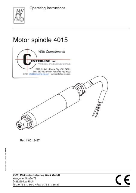
A 1.4 Possible uses and applicationsThe motorised <strong>spindle</strong> is designed to beused in machines for filing processes, suchas drilling, milling, cutting etc.A 2 Scope of delivery - Accessories<strong>Motor</strong>ised <strong>spindle</strong> <strong>4015</strong>with 2 m connection cableSpanner/wrench SW 8 1.001.40678Spanner/wrench SW 12 0.411.101212Brush set 0.411.0190consisting of:1 cleaning brush 0.229.32052 fine-bristle brushes 0.229.30013 cylinder brushes 0.229.30021Case(0.684.4116) andcontents padding (0.684.4128)Please retain for eventual inspection/repairreturns.Operating instructions 1.001.250123A 2.1 Accessory available onrequest:4Clamping device 4825 £ (1.001.4841) forpossible connection to external air- andwater cooling.4 Spindle <strong>4015</strong>
GBOPERATING INSTRUCTIONSA 3 Electrical connectionCheck that the available voltage andfrequency agree with the data on thefrequency converter.80 000REF• Dangers from disturbances in the energysupply, breaking of machine parts orother malfunctions, e.g.- unforseen ejection- unexpected starting- unexpected slipping/over-revving- incorrect rotation (chuck mechanism canloosen)must be prevented by appropriate safetyfeatures incorporated in the control unit(e.g. max. revolutions). KaVo EWL recommendsoperation by use of FrequencyConverter “ e@sy Drive 4425 “.Repair and maintenance work - apartfrom the activities described in theseinstructions for use - may be performedonly by qualified technical personnel.Disconnect the converter plug.Fasten the connecting wires to theconverter connection terminal.Ensure that the ground wire is correctlyfixed to the provided groundingterminal.Pay attention to the rotation of the<strong>spindle</strong> (if necessary, exchange twoconnections) !Spindle <strong>4015</strong> 5
A 4 Installation and operation ofmotor <strong>spindle</strong> <strong>4015</strong>• Compressed air supply of 0,5 to 0,8 barfor air-lock, must be clean and dry.• Use only compressed air free from dirt,water, and oil.• Never operate the <strong>spindle</strong> without airlock.Attach the 2.5 mm air hose 2 to the airconnector 1 in the direction of the arrow,then secure.Installation in <strong>spindle</strong> holder or clampingdeviceIt is recommended to use Clamping Device4815 (1.001.4841).Initial torque when clamping the <strong>spindle</strong>1,5 NM ± 20 % is to be maintained.Operation in any position betweenhorizontal and vertical (tool pointing down)is possible, using cooling throughthe <strong>spindle</strong> holder or an external coolingjacket.When inserting the <strong>spindle</strong> ensure itis located cylindrically.The <strong>spindle</strong> is designed for cooling via the<strong>spindle</strong> holder .<strong>Motor</strong> <strong>spindle</strong> <strong>4015</strong> is moisture-proof, butmust not be immersed in water.Tension can be applied over the wholehousing. However it is recommended toclamp over a wide surface, and whenpossible in the middle of the <strong>spindle</strong>.12• Only operate SF motor <strong>spindle</strong> <strong>4015</strong> witha tool or test-pin clamped in the chuck.Avoid, at all times, impact or blowsagainst the <strong>spindle</strong> or a clamped-in tool.• Only work with concentric tools.• Operate the <strong>spindle</strong> only in asuitableposition.• A too-high tension is to be avoided(effects the rotation and lifetime of the<strong>spindle</strong>)• Ensure correct rotation in accordancewith the direction of the arrow onthenameplate.6 Spindle <strong>4015</strong>
GBOPERATING INSTRUCTIONSA 5 Changing the chuckChanging of the chuck or a tool is tobe carried out only when the <strong>spindle</strong>is at a complete standstill. The convertermust be secured against accidental switchon,e.g. by pressing the mains switch to the“OFF“ position.12A 5.1 Removing the chuckHold shaft 3 with spanner/wrench 1 andturn nut 4 with spanner/wrench 2 indirection of the arrow >, until the nut canbe removed. Remove the installed chuck 5.123A 5.2 Insertion of the chuckHold shaft 3 with spanner/wrench 1 andturn nut 4 with spanner/wrench 2 indirection of the arrow < , until the nut canbe removed.Push chuck 5 with ineserted tool or testpininto the chuck location-position.Hold shaft 3 with spanner/wrench 1 andturn nut 4 with spanner/wrench 2 in thedirection of the arrow >, tightening snugly,thereby securing the tool or test-pin.4523Do not lubricate outer surfaces of thefrontal area,cone and centeringinsert.1123Spindle <strong>4015</strong> 7
A 6 Changing toolsHold shaft 3 with spanner/wrench 1 andloosen nut 5 with spanner/wrench 2 inthe direction of the arrow tightening snugly, therebysecuring the tool.241Insert replacement tool, dependent on shaftlength and manufacturer’s instructions, sofar into the chuck that the head or cuttingedges of the tool do not touch the chuck.512348 Spindle <strong>4015</strong>
GBOPERATING INSTRUCTIONSA 7 Maintenance• Under no circumstances, clean motor<strong>spindle</strong> <strong>4015</strong> with ultrasonics, steam,compressed air, etc.• Cleaning materials such as spray cleaners,solvents, etc must under no circumstancesbe brought into contact with the interiorof motor <strong>spindle</strong> <strong>4015</strong>.Chuck 3 must be cleaned frequently.Clean chuck receptacle and chuck 3 with abrush. Clean the threads of tightening nut2 and shaft 1, then lubricate lightly.Re-insert cleaned chuck 3 with tool 4 ortest-pin 4 into motor <strong>spindle</strong> <strong>4015</strong>(see A 5.2).0.229.3002120.229.30010.229.3205334Spindle <strong>4015</strong> 9
A 8 Technical DataRefers to motor <strong>spindle</strong> <strong>4015</strong> driven byconverter 4425:Stainless steel housingFrequency∅ 25,4 mm83 – 1,667 HzRevolutionsunder load)Torque5,000 – 80,000 min -1 (notmax. 4 NcmMaximum consumptionVoltageCurrentmax. 250 Wattmax. 32 Vmax. 8 AWeight(incl. 2 m connection cable)0,4 kgFurther installation dimensions, withtolerances, are available from KaVoEWL on request.Water cooling via Clamping Device Type4825Load limits:<strong>Motor</strong> <strong>spindle</strong> <strong>4015</strong>:Method of operation: S1(continuousoperation)Clamping device: 1.001.4841Converter: Type 442510 Spindle <strong>4015</strong>
GBOPERATING INSTRUCTIONSA 9 Available ChucksOrder No. ∅ Order No. ∅0.674.2122 0,3 0.674.2292 2,00.674.2132 0,4 0.674.2302 2,10.674.2142 0,5 0.674.2312 2,20.674.2152 0,6 0.674.2322 2,30.674.2162 0,7 0.674.2332 2,350.674.2172 0,8 0.674.2342 2,40.674.2182 0,9 0.674.2352 2,50.674.2192 1,0 0.674.2362 2,60.674.2202 1,1 0.674.2372 2,70.674.2212 1,2 0.674.2382 2,80.674.2222 1,3 0.674.2392 2,90.674.2232 1,4 0.674.2402 3,00.674.2242 1,5 0.674.2412 3,10.674.2252 1,6 0.674.2422 3,1750.674.2262 1,7 0.674.2432 3,20.674.2272 1,8 0.674.2442 3,30.674.2282 1,9 0.674.2452 3,40.674.2462 3,50.674.31324,0Standard ChucksGuarantee conditionsUnder the valid KaVo EWL delivery and payment conditions, KaVo EWL gives a guarantee of satisfactory function and freedom fromfaults in material and manufacture for the duration of 6 months from the date of sale certified by the vendor. After expiry of the warranty,KaVo gives a guarantee of another 6 months for damage attributable to deficiencies in the material or in manufacture.In the case of justifiable complaints, KaVo EWL shall supply spare parts or carry out repairs free of charge. KaVo EWL accepts no liabilityfor defects and their consequences which have arisen or could have arisen as a result of natural wear, improper handling, cleaning ormaintenance, noncompliance with the maintenance, operating and connecting instructions, corrosion, impurities in the air supply orchemical or electrical influences which are unusual or not admissible in accordance with KaVo’s instructions. The guarantee shall becomenull and void if defects or their consequences can be attributed to interventions in or modifications to the product. Guarantee claims canonly be validated if they are notified immediately in writing to KaVo EWL.When the product is sent in, it must be accompanied by a copy of an invoice or delivery note which clearly shows the fabrication number.Spindle <strong>4015</strong> 11
DECLARATION OF CONFORMITYK9-CONTRPL UNIT12 Spindle <strong>4015</strong>
SPARE PARTS GB SPINDLE <strong>4015</strong>Spare parts<strong>4015</strong> 1.001.24371.001.14071.001.03510.222.40410.200.63201.001.16920.200.63200.222.50221.000.74440.200.63081.001.06181.001.06171.001.03491.001.03340.675.0662Spindle <strong>4015</strong> 13