the user's guide - Lathem Time Corporation
the user's guide - Lathem Time Corporation
the user's guide - Lathem Time Corporation
- No tags were found...

Create successful ePaper yourself
Turn your PDF publications into a flip-book with our unique Google optimized e-Paper software.
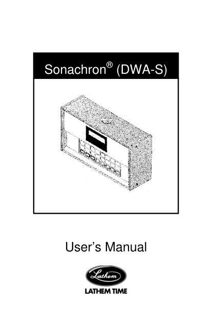
Sonachron ® (DWA-S)User’s Manual
La<strong>the</strong>m <strong>Time</strong> <strong>Corporation</strong>200 Selig Drive, SWAtlanta, GA 303361-800-241-49901-404-691-0400www.la<strong>the</strong>m.comDocument No. OMSC-0708Copyright © 2008 La<strong>the</strong>m <strong>Time</strong> <strong>Corporation</strong>.All rights reserved.
TABLE OF CONTENTSSPECIFICATIONS..................................................... 1INTRODUCTION ....................................................... 2QUICK START STEPS.............................................. 3DIP SWITCH SETTINGS........................................... 8PROGRAMMING A SECURITY CODE..................... 9UNLOCKING THE KEYPAD.................................... 10SETTING TIME AND DATE .................................... 10PROGRAMMING EVENTS (On/Off Controller)....... 11PROGRAMMING EVENTS (Bell Ringer)................. 12PROGRAMMING SIGNAL LENGTH (Bell Ringer) .. 12MANUAL LUNCH AND BREAKS (Bell Ringer) ....... 13SIGNAL ON/OFF..................................................... 14MANUAL OPERATION............................................ 14STANDBY POWER ................................................. 14RS485 SYNCH ........................................................ 15WIRING DIAGRAMS ............................................... 15WARRANTY............................................................ 24
SPECIFICATIONSInput Voltage 115 VAC (220 Optional)Input Frequency 50/60 HzInput Power 20 Watts MaxStandby Power 1.2 Ah, 6 V batteryStandby <strong>Time</strong> 10 DaysTiming Accuracy Per line frequencyNumber of Events 1440 (any combination of weekdays)Signal Duration Programmable – 1 to 99 secsDaylight Savings Automatic (Disable by dip switch)<strong>Time</strong> Display 12 or 24 hr selectableComm Port RS485 – ReceiverRelays10 Amp Dry ContactTemperature Range 0 C to 60 CVoltage Range +/ - 10 % of input voltageShipping Weight 7 lbDimensions 9 ¾”x 3 ¼”x 5 3/8”WARNING: This equipment generates uses and can radiateradio frequency energy and, if not installed and used inaccordance with <strong>the</strong> instruction manual, may cause interferenceto radio communications. It has been tested and found tocomply with <strong>the</strong> limits for a Class A computing device pursuant toSubpart J of Part 15 of FCC Rules, which are designed toprovide reasonable protection against such interference whenoperated in a commercial environment. Operation of thisequipment in a residential area is likely to cause interference, inwhich case, <strong>the</strong> user, at his own expense, will be required to takewhatever measures may be required to correct <strong>the</strong> interference.Page 1
INTRODUCTIONThe DWA-S is a single circuit signaling device which can beused as a bell ringer or on/off controller. It is capable of retainingup to 1440 separate events for each day of <strong>the</strong> week in memoryplus a floating lunch and break schedule which can be activatedwith a single key on <strong>the</strong> keypad or a remote switch. Automaticadjustment for daylight savings time change is also provided. Aliquid crystal display on <strong>the</strong> front of <strong>the</strong> unit displays <strong>the</strong> currenttime (in 12 or 24 hour format), date, and day of <strong>the</strong> week, bell oron/off control status, programming prompts, and indication ofoperation on standby power. A 24-button keypad is used forsetting time, programming events, manual operation of bells orcontrols, initiating lunch or break bells, and on/off control of <strong>the</strong>schedule. Access to programming functions and manual keys(MANUAL, START LUNCH, and START BREAK) is controlled bya user defined security code.The time keeping ability of <strong>the</strong> DWA-S is dependent on <strong>the</strong>power source frequency. A switch setting selects operationbased on 50 or 60 Hz. During A.C. power failures, <strong>the</strong> unitswitches to a quartz crystal time base and a 6 volt battery allows<strong>the</strong> unit to continue to keep time and retain all data for 10 days.Upon power resumption, <strong>the</strong> battery automatically recharges withcurrent limited to 1.5 Amperes.Page 2
QUICK START STEPSStep 1 – Mount Unit to Wall1. Unscrew 2 left screws to remove left side panel.2. Slide front panel left.3. Disconnect cable connector from right side of front panel.4. Slide front panel left and remove completely.5. Find a suitable location on <strong>the</strong> wall that allows at least 10inches of clearance on <strong>the</strong> left side to allow <strong>the</strong> front panel toslide on and off.6. Mark 3 hole positions on wall for mounting <strong>the</strong> unit.Mark Holes7. Remove plastic bushing from back of unit before mountingon <strong>the</strong> wall.8. Drill marked holes and install wall anchors in wall ifnecessary (not provided).Page 3
9. Secure unit to wall using screws (not provided).Drill HolesWallAnchorStep 2 – Swith Off Power to AC Circuit1. SWITCH OFF THE CIRCUIT THAT WILL FEED AC POWERTO THE UNIT BEFORE PROCEDING.Step 3 – Connect Wires for 115VAC or 24VAC BellsIMPORTANT! This unit is shipped from <strong>the</strong> factory as a BellRinger. To change to an ON/OFF controller, see DIP SwitchSetting on page 8. This section provides instructions forwiring 115VAC or 24VAC bells, see Wiring Diagrams onpages 20 – 22 for o<strong>the</strong>r options.1. There are three options for routing wires into <strong>the</strong> DWA-S:top, back or bottom. Select on of <strong>the</strong>se and remove <strong>the</strong> plug.2. Remove cover from terminal strip.Page 4
IMPORTANT: DO NOT PROCEED IF WIRE COLORS AREDIFFERENT THAN SHOWN OR IF YOU ARE UNSUREWHICH WIRES ARE AC HOT, AC NEUTRAL ANDGROUND. THERE IS RISK OF PERSONAL INJURY ANDDAMAGE TO THE UNIT THAT’S NOT COVERED BYWARRANTY. INEXPENSIVE TESTERS ARE AVAILABLEAT YOUR LOCAL HOME ELECTRICAL SUPPLY STOREFOR VERIFYING WIRES.3. Connect wires from power cord as follows: green (ground)wire to “GND”, white (AC neutral) wire to Line Neutral, andblack (AC Hot) wire to Line Hot.4. For 115VAC bells or horns, connect a jumper wire betweenLine Hot and CKT 1A. Connect <strong>the</strong> bell wires to AC Neutraland CKT 1B.5. For 24VAC bells or horns, connect a jumper wire betweenAC Hot and CKT 1A. Connect <strong>the</strong> transformer115VAC/primary wires to AC Neutral and CKT 1B. Connect<strong>the</strong> transformer 24VAC/secondary wires to <strong>the</strong> 24 V bells orhorns.NOTE: See pages 20 - 22 for o<strong>the</strong>r wiring options that use<strong>the</strong> COM, BREAK and LUNCH terminals.Step 4 – Turn on Power Switch1. Press cover onto Terminal Block.2. Set Power switch to up position.Replace CoverPower SwitchPage 5
Step 5 – Secure Cover1. Align front panel in track and slide half way to right.2. Secure ribbon cable on right edge of front panel.3. Slide front panel all <strong>the</strong> way closed making sure that <strong>the</strong>cable lays down.4. Attach red battery wire onto battery post.5. Secure left side panel with <strong>the</strong> screws.CPU BoardReconnect CableRed BatteryWireStep 8 – Restore Power to AC Circuit1. MAKE SURE THE SIDE COVERS ARE SECURE THENSWITCH ON THE AC POWER TO THE CIRCUITFEEDING POWER TO THE UNIT.Page 6
Step 9 – Test Signaling1. Your display should appear as shown in <strong>the</strong> picture below. Ifnot, please contact your dealer or La<strong>the</strong>m <strong>Time</strong> directly.SECURITY CODE2. Enter a security code using <strong>the</strong> day of week keys (remember<strong>the</strong> days that you selected).3. Press Run to return to <strong>the</strong> normal display showing currenttime of day.4. Press <strong>the</strong> Manual Bells button and confirm that <strong>the</strong> bells orhorns are sounding properly. If not, please contact yourdealer or La<strong>the</strong>m <strong>Time</strong> directly.5. Set <strong>the</strong> time and date, and program <strong>the</strong> unit as described in<strong>the</strong> following pages.Page 7
DIP SWITCH SETTINGSTo access <strong>the</strong> dip switches, remove<strong>the</strong> two screws holding <strong>the</strong> left sidepanel in place and remove <strong>the</strong>panel. Dip Switches 1, 2, and 3 aremonitored at all times and changestake effect immediately. Dip Switch4 is read only at power up. Tochange <strong>the</strong> setting for this switch,<strong>the</strong> unit must be powered completelyoff and back on. Dip Switch 2 isalso used to reset <strong>the</strong> security code.Any change in its setting will allowyou to view and change <strong>the</strong> securitycode. The unit is shipped from <strong>the</strong> factory with all dip switches in<strong>the</strong> ON position. The chart below shows <strong>the</strong> dip switch settings:DipSwitchDescription ON OFF1 <strong>Time</strong> KeepingFrequency2 <strong>Time</strong> Format(Security Code Access)60 Hz 50 Hz12 Hr 24 Hr3 Daylight Savings <strong>Time</strong>ChangeEnabledDisabled4 Operation BellRingerOn/OffControllerPage 8
PROGRAMMING A SECURITY CODEUpon power up you are allowed to enter a security code torestrict access to programming functions. When <strong>the</strong> unitdisplays “SECURITY CODE”, press from one to four Day of <strong>the</strong>Week keys. This is your security code. The ERASE EVENT keycan be used to clear <strong>the</strong> code for re-entry. Press <strong>the</strong> RUN key toadvance <strong>the</strong> programming when you are satisfied with <strong>the</strong>security code. The unit will prompt “UNSECURED MANUALFWD TO CHANGE.” If this selection is chosen, only <strong>the</strong>programming functions will require <strong>the</strong> security code to beaccessed. MANUAL, START LUNCH, and START BREAK willbe unsecured. Pressing <strong>the</strong> selection requires <strong>the</strong> security codeto be entered prior to both accessing <strong>the</strong> programming functionsand using <strong>the</strong> MANUAL, START LUNCH, and START BREAKSkeys. The remote START LUNCH and START BREAKswitches do not require <strong>the</strong> security code to activate Lunch orBreak schedules. After choosing <strong>the</strong> level of security desired,press <strong>the</strong> RUN key to advance to <strong>the</strong> normal display.If unlimited access to all functions is desired (no security), press<strong>the</strong> RUN key without pressing any Day of <strong>the</strong> Week keys when<strong>the</strong> unit prompts for <strong>the</strong> security code. The unit will advance to<strong>the</strong> normal display and no security code will be required toaccess any function.To change or view <strong>the</strong> security code, remove <strong>the</strong> left side panel,toggle Dip Switch 2, and return it to <strong>the</strong> desired position. Thecurrent security code will be displayed. Replace <strong>the</strong> side panel.To change <strong>the</strong> code, press <strong>the</strong> ERASE EVENT key to clear <strong>the</strong>current code and program <strong>the</strong> new code in <strong>the</strong> same manner asdescribed above. If you do not wish to change <strong>the</strong> code, press<strong>the</strong> RUN key until <strong>the</strong> normal display returns.Page 9
UNLOCKING THE KEYPADTo unlock <strong>the</strong> keypad, press <strong>the</strong> Day of <strong>the</strong> Week keys youprogrammed for <strong>the</strong> security code followed by RUN. Thesecurity keys must be pressed in <strong>the</strong> exact order as <strong>the</strong>y wereoriginally entered. The display should read “SELECTFUNCTION.” To relock <strong>the</strong> keypad, simply press RUN. Thekeypad must be unlocked, or no security programmed, to accessprogramming functions. Remote operation of Start Lunch orStart Break switches do not depend on <strong>the</strong> status of <strong>the</strong> keypador security code. Pressing <strong>the</strong> MANUAL, START LUNCH, orSTART BREAK key while in <strong>the</strong> programming mode (keypadunlocked) will ring <strong>the</strong> bells and return <strong>the</strong> unit to <strong>the</strong> normaldisplay with <strong>the</strong> keypad secured. The PRGM LUNCH, PRGMBREAK, SIGNAL LENGTH, and PRGM REVIEW keys may bepressed while <strong>the</strong> keypad is locked to view <strong>the</strong> current settings of<strong>the</strong>ir respective functions.SETTING TIME AND DATEFollow procedure above to unlock keypad. The display shouldread “SELECT FUNCTION.” To set <strong>the</strong> time, simply press <strong>the</strong>SET TIME key and use <strong>the</strong> FAST FWD and SLOW FWD keys toadvance to <strong>the</strong> correct time. The seconds will be set to zerowhen ei<strong>the</strong>r forward key is pressed. Selecting ano<strong>the</strong>r functionor pressing RUN will start <strong>the</strong> seconds indexing. To set <strong>the</strong>month, date, or year, press <strong>the</strong> SET MONTH, SET DAY, or SETYEAR key, respectively. Use <strong>the</strong> forward keys to advance to <strong>the</strong>appropriate setting. Continue to next programming procedure orpress RUN to return to <strong>the</strong> normal display. The day of <strong>the</strong> weekwill be determined automatically based on <strong>the</strong> date.Page 10
PROGRAMMING EVENTS(On/Off Controller)NOTE: Dip Switch 4 must be set to OFF (see page 8)With “SELECT FUNCTION” displayed, press <strong>the</strong> PRGMEVENTS key. The display should read “CONTROL 12:00 AM.”Use <strong>the</strong> FAST FWD and SLOW FWD keys to advance <strong>the</strong>displayed time to <strong>the</strong> desired event time. Once <strong>the</strong> event time isreached, press <strong>the</strong> day of <strong>the</strong> week keys (Sun, Mon, Tue, etc.)to indicate on which day(s) <strong>the</strong> control should operate. Pressinga key once will display <strong>the</strong> day of <strong>the</strong> week and pressing it againwill remove it. The control will default to OFF, press <strong>the</strong> SIGNALON/OFF key to toggle <strong>the</strong> control between OFF and ON. Onceyou have chosen <strong>the</strong> day(s) and on/off status for <strong>the</strong> event, use<strong>the</strong> forward keys to advance <strong>the</strong> time to <strong>the</strong> next event and enter<strong>the</strong> day(s) and On/Off status. Continue in this fashion until allcontrols are programmed. Press RUN to lock <strong>the</strong> keypad andreturn to <strong>the</strong> normal display.While in <strong>the</strong> Program Events function, <strong>the</strong> PRGM REVIEW andERASE EVENT keys can be used to scan and erase events,respectively. To scan programmed events, simply press <strong>the</strong>PRGM REVIEW key. The next event in memory will be locatedand displayed. Pressing <strong>the</strong> key repeatedly will scan through allevents sequentially. To erase an event, locate <strong>the</strong> event andpress <strong>the</strong> ERASE EVENT key.PRGM REVIEW may also be used when <strong>the</strong> keypad is locked.Pressing <strong>the</strong> key will display <strong>the</strong> next scheduled event. Press<strong>the</strong> key repeatedly to scan all programmed events. The normaldisplay will return after 5 seconds or when <strong>the</strong> RUN key ispressed. ALL LUNCH and BREAK keys and remote switchesare inactive when using <strong>the</strong> unit as an On/Off Controller.Page 11
PROGRAMMING EVENTS(Bell Ringer)NOTE: Dip Switch 4 must be set to ON (see page 8)With “SELECT FUNCTION” displayed, press <strong>the</strong> PRGMEVENTS key. The display should read “SIGNAL 12:00 AM” “ONDAYS:” Use <strong>the</strong> FAST FWD and SLOW FWD keys to advance<strong>the</strong> displayed time to <strong>the</strong> desired event time. Once <strong>the</strong> eventtime is reached, press <strong>the</strong> day of <strong>the</strong> week keys (Sun, Mon, Tue,etc.) to indicate on which day(s) <strong>the</strong> bells should ring. Pressing akey once will display <strong>the</strong> day of <strong>the</strong> week and pressing it againwill remove it. Once you have chosen <strong>the</strong> day(s) for <strong>the</strong> event,use <strong>the</strong> forward keys to advance <strong>the</strong> time to <strong>the</strong> next event andenter <strong>the</strong> days. Continue in this fashion until all events areprogrammed . Press RUN to lock <strong>the</strong> keypad and return to <strong>the</strong>normal display.While in <strong>the</strong> Program Events function, <strong>the</strong> PRGM REVIEW andERASE EVENT keys can be used to scan and erase events,respectively. To scan programmed events, simply press <strong>the</strong>PRGM REVIEW key. The next event in memory will be locatedand displayed. Pressing <strong>the</strong> key repeatedly will scan through allevents sequentially. To erase an event, locate <strong>the</strong> event andpress <strong>the</strong> ERASE EVENT key.PRGM REVIEW may also be used when <strong>the</strong> keypad is locked.Pressing <strong>the</strong> key will display <strong>the</strong> next scheduled event. Press<strong>the</strong> key repeatedly to scan all programmed events. The normaldisplay will return after 5 seconds or when <strong>the</strong> RUN key ispressed.PROGRAMMING SIGNAL LENGTH(Bell Ringer)The signal length defaults to 5 seconds. To change this value,unlock <strong>the</strong> keypad and press <strong>the</strong> SIGNAL LENGTH key. Thecurrent signal length will be displayed. Use <strong>the</strong> FAST FWD andSLOW FWD keys to change <strong>the</strong> setting. Values from 1 to 99seconds are allowed. Press RUN to return to <strong>the</strong> normal display.To review <strong>the</strong> signal length without unlocking <strong>the</strong> keypad, simplypress <strong>the</strong> SIGNAL LENGTH key. The normal display will returnafter 5 seconds or when <strong>the</strong> RUN key is pressed.Page 12
MANUAL LUNCH AND BREAKS(Bell Ringer)This function provides a means of programming set lunch andbreak lengths which can be initiated at various times during <strong>the</strong>day. It is only available when <strong>the</strong> unit is used as a Bell Ringerand operating on AC power. Pressing <strong>the</strong> START LUNCH orSTART BREAK key at <strong>the</strong> keypad (or a remote momentaryswitch connected to <strong>the</strong> unit) causes <strong>the</strong> bells to signal and adisplayed timer to begin counting down <strong>the</strong> programmed lunch orbreak time. When <strong>the</strong> timer counts to zero, <strong>the</strong> bellsautomatically signal again to indicate <strong>the</strong> end of lunch or break.This feature is especially convenient for facilities which areserviced by a lunch truck. When <strong>the</strong> truck arrives on site, simplypress <strong>the</strong> remote lunch switch to begin <strong>the</strong> lunch break. Thisfunction also allows a warning bell to ring before <strong>the</strong> final lunchor break bell.To program a lunch, unlock <strong>the</strong> keypad <strong>the</strong>n press <strong>the</strong> PRGMLUNCH key. Use <strong>the</strong> forward keys to program <strong>the</strong> desired lunchlength, 00 to 99 minutes. Press <strong>the</strong> PRGM LUNCH key asecond time to display <strong>the</strong> length of time (0 to 9 minutes) awarning bell will ring before <strong>the</strong> ending bell rings. The default is0. Use <strong>the</strong> forward keys to change this value. Press <strong>the</strong> RUNkey to return to <strong>the</strong> normal display. Program breaks in <strong>the</strong> samemethod.Scheduled bells are inhibited during lunch and break periods. If<strong>the</strong> schedule is turned off or <strong>the</strong> MANUAL key pressed while alunch or break period is in progress, <strong>the</strong> remaining lunch orbreak time will be canceled. If <strong>the</strong> wrong key was pressed,LUNCH instead of BREAK or BREAK instead of LUNCH, simplypress <strong>the</strong> correct key before <strong>the</strong> programmed time has expired.The bells will not ring again and <strong>the</strong> time already elapsed will beapplied towards <strong>the</strong> programmed time for <strong>the</strong> break or lunch. Toreview <strong>the</strong> programmed times without unlocking <strong>the</strong> keypad,simply press <strong>the</strong> PRGM LUNCH or PRGM BREAK key. Thenormal display will return after 5 seconds or when <strong>the</strong> RUN keyis pressed.Page 13
SIGNAL ON/OFFPressing <strong>the</strong> SIGNAL ON/OFF key when <strong>the</strong> keypad is unlockedchanges <strong>the</strong> On/Off status of <strong>the</strong> programmed schedule. When<strong>the</strong> status is ON, bells or controls will operate based on <strong>the</strong>schedule. When <strong>the</strong> status is OFF, <strong>the</strong> schedule is ignored andonly <strong>the</strong> manual key will operate <strong>the</strong> bells or controls. Thecurrent On/Off status of controls will remain active until MANUALis pressed or <strong>the</strong> schedule reactivated. Press RUN to return to<strong>the</strong> normal display. When <strong>the</strong> schedule is inactive, SCHEDULEOFF will be shown below <strong>the</strong> time on <strong>the</strong> display.MANUAL OPERATIONPressing <strong>the</strong> MANUAL key when <strong>the</strong> unit is being used as a BellRinger will cause <strong>the</strong> bells to signal for <strong>the</strong> length of time <strong>the</strong> keyis pressed. This provides a means of operating <strong>the</strong> bells atunscheduled times. Pressing MANUAL while lunch or break iscounting down will operate <strong>the</strong> bells and cause <strong>the</strong> remaininglunch or break time to be canceled.Pressing <strong>the</strong> MANUAL key when <strong>the</strong> unit is operating as onOn/Off Controller will toggle <strong>the</strong> current On/Off status of <strong>the</strong>controls.The MANUAL key will not ring bells if <strong>the</strong> unit is operating onstandby power.STANDBY POWERDuring AC power failures, <strong>the</strong> DWA-S switches to a quartzcrystal time base to maintain <strong>the</strong> time keeping ability of <strong>the</strong> unit.A 6 volt battery allows <strong>the</strong> unit to continue operation and retain<strong>the</strong> programmed schedule for 10 days. An * on <strong>the</strong> lower line of<strong>the</strong> display indicates operation on Standby Power.Programming, schedule review, and manual toggling of <strong>the</strong>On/Off control status are available when operating on batteryback up. If operating as a Bell Ringer, <strong>the</strong> MANUAL, STARTLUNCH, and START BREAK keys, and <strong>the</strong> remote STARTLUNCH and START BREAK switches are inactive during ACpower failures. Schedule operation is also inactive whenoperating as a Bell Ringer.Page 14
RS485The DWA-S comes equipped with an RS485 receiver which canbe used to synchronize <strong>the</strong> time and date of <strong>the</strong> unit with o<strong>the</strong>requipment. The option supplies three leads on <strong>the</strong> power supplyboard for connecting to <strong>the</strong> sending device. The interconnectioncable between devices should be a minimum of 3 meters long toprevent interference to radio communications as required byFCC regulations. Cables less <strong>the</strong>n 3 meters in length require aFair-Rite bead (La<strong>the</strong>m Part # VII0058) installed around <strong>the</strong>cable. The figure below indicates <strong>the</strong> signal names andcorresponding wire colors.SignalReceive ( + )Receive ( - )Signal GroundWire ColorWhiteYellowBlackNOTE: Preferred cable is CAT-3 or CAT-5 twisted-pair, up to4,000 feet in length.WIRING DIAGRAMSFIGURE 1:CONNECTION FOR DWA-S TO LTRX-512RS-485DWA-S DSD+ -RS-485DSD+ -RS-485RS-485RS-485 MASTER RS-485DSDDSDDSD CLOCK DSD+ - + -+ -+ -MODEM1 2 3 4 5 6 7 8 9 10 11 12 13TxD G RxD D D G S D DNN YD + - D N + -CRS-232 RS-485 SYNCPULSE OUTSYNCHOST COMMUNICATIONSLTR8-512 & LTR8-512M OnlyD D+ -SYNCINRS-485DATA SYNC~ ~12V~ACOUT250maPorts are located on <strong>the</strong>back of <strong>the</strong> Display UnitNOTE: Since <strong>the</strong> Sync In port can send as well as receive, 30 extradevices can connect here. If you already have a MasterSource, such as an LTR-0, connect it and its string of clocks to<strong>the</strong> Sync In port, for a total of up to 60 devices.Page 15
FIGURE 2:CONNECTION FOR DWA-S TO LTR-0FIGURE 3:CONNECTION FOR DWA-S TO LTR-GPSPage 16
FIGURE 4:CONNECTING RC-MS TO SYNCH DWA-S ORLTR-0NOTE: A 9vDC Power Adapter (not shown) is also required for <strong>the</strong>RC-MS.FIGURE 5:OMC – DWA-S INTERCONNECTIONPage 17
Sonachron (DWA-S) can be synchronized to La<strong>the</strong>m’s LTRx-512master, LTR-0 master, LTR-GPS receiver, RC-MS master orOmni:ChronII time clock reference devices. Distance from <strong>the</strong>source can be extended using La<strong>the</strong>m’s SWIFT485+ repeater.Omni:ChronII <strong>Time</strong> Recorder can be equipped with an optionalRS485 transmitter for communication with <strong>the</strong> DWA-S. Wheninstalled, <strong>the</strong> DWA-S will synchronize with <strong>the</strong> time and datefrom <strong>the</strong> Omni:ChronII each minute.When installing multiple DWA-S units, all units EXCEPT <strong>the</strong> oneat <strong>the</strong> end of <strong>the</strong> RS485 line require jumper E2 be cut. When E2is installed, a 100 ohm terminating resistor is internallyconnected across <strong>the</strong> RS485 line to reduce <strong>the</strong> signal reflectionand <strong>the</strong>reby improve reception. E2, located on <strong>the</strong> far left side of<strong>the</strong> CPU circuit board, can be accessed by removing <strong>the</strong> left endcap. Refer to <strong>the</strong> Figure on Page 8.Page 18
Page 19
FIGURE 6:115/220 VAC BELL WIRINGFIGURE 7:LOW VOLTAGE AC BELL WIRINGPage 20
FIGURE 8:LOW VOLTAGE DC BELL WIRINGFIGURE 9:115/220 VAC CONTROL WIRINGPage 21
FIGURE 10:LOW VOLTAGE AC CONTROL WIRINGFIGURE 11:LOW VOLTAGE DC CONTROL WIRINGPage 22
FIGURE 12:DRY CONTACT WIRING FOR PAGINGSYSTEM OR TONE GENERATORPage 23
Limited One-Year Limited WarrantyLa<strong>the</strong>m warrants <strong>the</strong> hardware products described in this <strong>guide</strong> against defects inmaterial and workmanship for a period of one year from date of original purchasefrom La<strong>the</strong>m or from an authorized La<strong>the</strong>m reseller. The conditions of this warrantyand <strong>the</strong> extent of <strong>the</strong> responsibility of La<strong>the</strong>m <strong>Time</strong> <strong>Corporation</strong> (“La<strong>the</strong>m”) under thiswarranty are listed below.1. This warranty will become void when service performed by anyone o<strong>the</strong>rthan an approved La<strong>the</strong>m warranty service dealer results in damage to <strong>the</strong>product.2. This warranty does not apply to any product which has been subject toabuse, neglect, or accident, or which has had <strong>the</strong> serial number altered orremoved, or which has been connected, installed, adjusted, or repairedo<strong>the</strong>r than in accordance with instructions furnished by La<strong>the</strong>m.3. This warranty does not cover dealer labor cost for removing and reinstalling<strong>the</strong> machine for repair, or any expendable parts that are readily replaceddue to normal use.4. The sole responsibility of La<strong>the</strong>m under this warranty shall be limited torepair of this product, or replacement <strong>the</strong>reof, at <strong>the</strong> sole discretion ofLa<strong>the</strong>m.5. If it becomes necessary to send <strong>the</strong> product or any defective part to La<strong>the</strong>mor any authorized service dealer, <strong>the</strong> product must be shipped in its originalcarton or equivalent, fully insured with shipping charges prepaid. La<strong>the</strong>m willnot assume any responsibility for any loss or damage incurred in shipping.6. WARRANTY DISCLAIMER AND LIMITATION OF LIABILITY: Except only<strong>the</strong> limited express warranty set forth above, <strong>the</strong> products are sold with noexpressed or implied warranties of any kind, and <strong>the</strong> implied warranties ofmerchantability and fitness for a particular purpose are hereby expresslydisclaimed. No warranties are given with respect to products purchasedo<strong>the</strong>r than from La<strong>the</strong>m or an authorized La<strong>the</strong>m reseller and any suchproducts are purchased "as is, with all faults." In no event will La<strong>the</strong>m beliable for any direct, indirect, special, incidental or consequential damagesarising out of or in connection with <strong>the</strong> delivery, use or inability to use, orperformance of this product. In <strong>the</strong> event any limited remedy given hereinshall be deemed to have failed of its essential purpose, La<strong>the</strong>m's maximumliability shall be to refund <strong>the</strong> purchase price upon return of <strong>the</strong> product.7. Proof of date of purchase from La<strong>the</strong>m or an authorized La<strong>the</strong>m reseller isrequired for warranty service on this product.8. This Warranty grants specific legal rights. Additional legal rights, which mayvary by locale, may also apply.9. Should any difficulties arise with <strong>the</strong> performance of this product duringwarranty, or with any La<strong>the</strong>m authorized service centers, contact La<strong>the</strong>m<strong>Time</strong> at <strong>the</strong> address below.La<strong>the</strong>m <strong>Time</strong>200 Selig Drive, SW, Atlanta, GA 303361-404-691-0405www.la<strong>the</strong>m.comPage 24
OMSC-0708