Airboss OM Guide - Keane Environmental
Airboss OM Guide - Keane Environmental
Airboss OM Guide - Keane Environmental
- No tags were found...

Create successful ePaper yourself
Turn your PDF publications into a flip-book with our unique Google optimized e-Paper software.
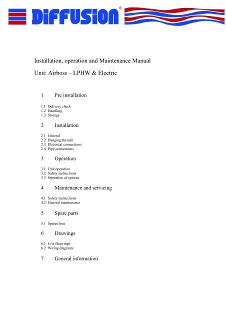
1 Pre Installation.1.1 Delivery Check.On receipt of delivery check the unit and packaging for any damage. Report any transportdamage to Diffusion immediately, or within three working days.Make sure that all ordered parts have been delivered. Any shortfall should be reported toDiffusion immediately.1.2 Handling.The unit must be handled with care, to avoid damage to the grille and painted surfaces.Distortion of the chassis and damage to the internal components may occur as a result fromimpact.1.3 Storage.Units should not be stacked. The units should be carefully stored under dry and dust freeconditions in their packaging until required.2 Installation.2.1 General.Make sure that the structure on which the unit will be suspended/mounted is capable ofsupporting the weight of the unit. The weight is shown on the G/A drawings.The front top of the unit is the air inlet, therefore do not obstruct in any way, as unit failurewill result.The electrical control box/connections are located at the right hand end (facing the unit fronton) of the unit, and can be accessed by removing the front panel (4 screws).The unit should be positioned above the door and as close as possible at a maximum height of2.5m from the finished floor level.2.2 Hanging the unit.The unit is to be mounted and levelled using the two purpose designed mounting bracketssupplied. Each bracket has two 13Ømm and can be mounted either from the ceiling ordoor/wall structure without the unit in place. When the two brackets have been fixed/levelledthe unit can then be placed onto the brackets and fixed into position using the correct securinghole. The unit should be mounted with the curved punched inlet facing into the building.2.3 Electrical connections.1050 3/6kw electric unit & all LPHW versionsThe unit requires a 230v/1ph/50Hz electrical supply that is terminated within the control boxand should be connected in accordance with the wiring diagram and current IEE regulations.1050 6/9kw, 1550 8/12kw & 2050 12/18kw unitsThe unit requires a 415v/3ph/50Hz electrical supply that is terminated within the control boxand should be connected in accordance with the wiring diagram and current IEE regulations.
Cable entry points are detailed on the G/A drawings/sales literature and are 20/25mmdiameter.The unit has an integral controlbox that houses the speed transformer, controller and electricalconsumables. This can be accessed by removing the front panel.Warning: The unit must be earthed. Make sure that the mains supply you are workingon is switched off. Always refer to wiring diagram.2.4 Pipe connections15mm (OD) plain copper tails on 1050 model and 22mm (OD) plain copper tails on 1550 &2050 models. Refer to GA drawings for exact details of pipe entries and connections.3 Operation.3.1 Unit operation.Electric Version: Remote control plate housing unit: on/off, speed: high/low, heat: off/low,heat: off/high. The unit can be run in a fan only mode by switching both heating switches tooff. Should the airflow fail, or reduce to dangerously low levels due to obstruction or fanfailure, the manual over heat safety cut out will operate. This cuts the electrical power to theheating elements and shuts them down, which prevents the unit from seriously over heatingand becoming a safety hazard.LPHW Version: Remote control plate housing 4 speed switches and off.3.2 Safety Instructions.Warning:Do not insert any objects into the inlet or discharge openings.Never block the inlet or discharge openings.During operation the surface of the unit can become hot.Make sure mains power supply is switched off, whilst working on the unit.When the unit is switched off, residual heat will be present for a period of time, DO NOTremove the access panel or carry out any maintenance until the heat has dissipatedsufficiently to a level where it is safe to do so.3.3 Operation of options.Remote or return air Thermostats: To control electric heating on/off on electric version andfan on/off on LPHW version (Standard or Energy saving controls).Low water temperature cut out: Provides automatic shutdown of the fan/motor when boilershave been switched off (standard controls only).Summer/Winter switch (manual): Used in conjunction with the room thermostat and/or lowwater temperature cut out, this will allow the fan only to run for air movement (standardcontrols only).BMS interface relay: 24vac relay and base.Energy saving controls: Refer to controls O&M manual for details.
PIR Sensor – Unit mounted sensor to give automatic on/off control of the unit.4 Maintenance and Servicing.4.1 Safety Instructions.Warning: Before maintaining/servicing the unit:Make sure mains power is switched off, (i.e. fused spur or main circuit breaker).Wait until fans/motors have stopped rotation.Allow the unit to cool down after operation.Coil fins and elements fins can be sharp.Use all necessary safety equipment required by current HSE legislation.4.2 General maintenance.Access to all the components can be made via the removable core/grille (push release).Filter: Must be maintained at regular intervals. Exact intervals will be determined byenvironmental/building conditions (LPHW only).Fans: Impeller blades should be lightly brushed/cleaned at regular intervals; this is to removeany dust that has gathered. The fans have sealed for life bearings and therefore require nolubrication.LPHW Coils: Fins should be lightly brushed/cleaned at regular intervals; this is to remove anydust that has gathered.Electric Elements: Fins should be lightly brushed/cleaned at regular intervals; this is toremove any dust that has gathered.5 Spares Parts.5.1 Spares listsContact spares department6 Drawings.6.1 G/A DrawingsAs attached drawings6.2 Wiring DiagramsAs attached drawings
7 General information.The goods supplied are subject to et <strong>Environmental</strong> standard terms and conditions of sale, acopy of which is available on request. If anything in these installation operation andmaintenance instructions conflicts with the terms and conditions, then the terms andconditions will apply.Each unit is individually tested both mechanically and electrically. A test label is attached toeach unit signed by the tester for each test completed.Liability for the contents of this guide:However much care might have been taken in ensuring the correctness and, where necessary,completeness of the description of the relevant parts, et <strong>Environmental</strong> disclaims all liabilityfor damage resulting from any inaccuracies and/or deficiencies in this guide.Should you detect any errors or ambiguities in this guide then we would be pleased to hearfrom you: it helps us to improve our documentation even further.et <strong>Environmental</strong> has a policy of continuous development and therefore reserves the right toalter information contained in this literature without prior notice.If you require any further information please contact the following:Diffusion47 Central AvenueWest MoleseySurrey KT8 2QZTel: 0208 783 0033 email: diffusion@etenv.co.ukFax: 0208 783 0140 Web: www.diffusion-group.co.uk
Declaration of ConformityThis certificate declares that the following et <strong>Environmental</strong> plc products:Over door heaters, space heating units, fan convectors and vent units.Have been designed and manufactured in accordance with the requirements of thecouncil directive 89/336/EEC relating to Electromagnetic Compatibility by theapplication of the following EMC generic standards.EN50 081.1 1992EN50 082.1 1992Providing installation is carried out in compliance with BS 5345 & BS 6959 and thatcorrect EMC practices are applied, and that any cable glands and connections to theunits are approved for use in the relevant environment.