Service Bulletin - Cessna
Service Bulletin - Cessna
Service Bulletin - Cessna

Create successful ePaper yourself
Turn your PDF publications into a flip-book with our unique Google optimized e-Paper software.
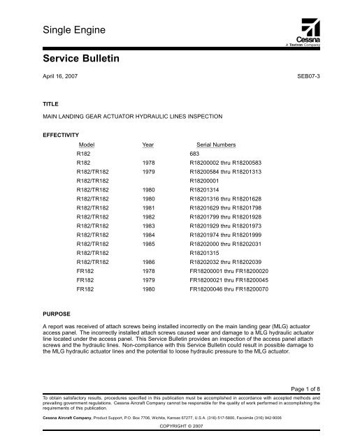
Single Engine<strong>Service</strong> <strong>Bulletin</strong>April 16, 2007SEB07-3TITLEMAIN LANDING GEAR ACTUATOR HYDRAULIC LINES INSPECTIONEFFECTIVITYModel Year Serial NumbersR182 683R182 1978 R18200002 thru R18200583R182/TR182 1979 R18200584 thru R18201313R182/TR182R18200001R182/TR182 1980 R18201314R182/TR182 1980 R18201316 thru R18201628R182/TR182 1981 R18201629 thru R18201798R182/TR182 1982 R18201799 thru R18201928R182/TR182 1983 R18201929 thru R18201973R182/TR182 1984 R18201974 thru R18201999R182/TR182 1985 R18202000 thru R18202031R182/TR182R18201315R182/TR182 1986 R18202032 thru R18202039FR182 1978 FR18200001 thru FR18200020FR182 1979 FR18200021 thru FR18200045FR182 1980 FR18200046 thru FR18200070PURPOSEA report was received of attach screws being installed incorrectly on the main landing gear (MLG) actuatoraccess panel. The incorrectly installed attach screws caused wear and damage to a MLG hydraulic actuatorline located under the access panel. This <strong>Service</strong> <strong>Bulletin</strong> provides an inspection of the access panel attachscrews and the hydraulic lines. Non-compliance with this <strong>Service</strong> <strong>Bulletin</strong> could result in possible damage tothe MLG hydraulic actuator lines and the potential to loose hydraulic pressure to the MLG actuator.Page 1 of 8To obtain satisfactory results, procedures specified in this publication must be accomplished in accordance with accepted methods andprevailing government regulations. <strong>Cessna</strong> Aircraft Company cannot be responsible for the quality of work performed in accomplishing therequirements of this publication.<strong>Cessna</strong> Aircraft Company, Product Support, P.O. Box 7706, Wichita, Kansas 67277, U.S.A. (316) 517-5800, Facsimile (316) 942-9006COPYRIGHT © 2007
COMPLIANCERecommended: should be accomplished within the next 100 hours of operation or during the next scheduled100 hour or annual/12 month type inspection, whichever occurs first.APPROVALFAA approval has been obtained on technical data in this publication that affects airplane type design.For Reims Aviation Airplanes: DGAC approval has not been obtained on technical data in this publication. Theaffected "F" model and serial number airplanes are included for informational purposes. <strong>Cessna</strong> considerscompliance recommended on "F" model airplanes regardless.MAN-HOURSApproximately 1.6 man-hours for inspectionIf necessary, approximately 1.5 man-hours to replace one hydraulic line, and 0.3 man-hour for each additionalline replacementMATERIALThe parts below are available from <strong>Cessna</strong> Parts Distribution through an appropriate <strong>Cessna</strong> <strong>Service</strong> Stationfor the suggested list price shown.Part Number Description Qty/Airplane PriceMS27039-1-09 Screw 1 (if required) $ 0.27 (PS) ea MQ 100MS27039-1-12 Screw 5 (if required) $ 0.11 (PS) ea MQ 100MS27039-1-14 Screw 2 (if required) $ 0.17 (PS) ea MQ 100MS27039-1-16 Screw 10 (if required) $ 0.24 (PS) ea MQ 1002280001-2 MLG Hydraulic-1 (if required) $ 157.00 (S) eaActuator Down Line, Left2280001-11 MLG Hydraulic-1 (if required) $ 167.00 (S) eaActuator Up Line, Right2280001-12 MLG Hydraulic-1 (if required) $ 245.00 (S) eaActuator Up Line, Left2280001-35 MLG Hydraulic-Actuator Down Line, Right1 (if required) $ 180.00 (S) eaALL PRICES SUBJECT TO CHANGE WITHOUT NOTICEACCOMPLISHMENT INSTRUCTIONSChange In Weight And BalanceNegligibleSEB07-3Page 2 April 16, 2007
Material InformationThe parts below may be necessary:New P/N Quantity Description Old P/N DispositionMS27039-1-09 1 Screw NAS221-9 DiscardMS27039-1-12 5 Screw NAS221-12 DiscardMS27039-1-14 2 Screw NAS221-14 DiscardMS27039-1-16 10 Screw NAS221-16 Discard2280001-2 1 MLG Hydraulic-Actuator SameDiscardDown Line, Left2280001-11 1 MLG Hydraulic-Actuator Up SameDiscardLine, Right2280001-12 1 MLG Hydraulic-Actuator Up SameDiscardLine, Left2280001-35 1 MLG Hydraulic-ActuatorDown Line, Right2280001-1 Discard1. Prepare the airplane for maintenance.A. Make sure that all switches are in the OFF/NORM position.B. Disconnect electrical power from the airplane.(1) Disconnect the airplane battery.(2) Disconnect external electrical power.C. Attach maintenance warning tags to the battery and external power receptacle that have "DO NOTCONNECT ELECTRICAL POWER - MAINTENANCE IN PROGRESS" writtenonthem.2. Remove and keep the bolts that attach the rear seats to the airplane, and move the seats away from the2211042-2 Access Door. (Refer to the Model R182 and R182 Series 1978 thru 1986 <strong>Service</strong> Manual.)3. (Refer to Figure 1, Detail A.) Remove the carpet from the area of the 2211042-2 Access Door.4. (Refer to Figure 1, Detail A.) Remove the 2211042-2 Access Door as follows:A. As you remove each screw, record the location and length of it.NOTE: If an installed screw is more than the length specified in the applicable illustrated partscatalog or in Figure 1, Detail A, there can be damage to the hydraulic lines near to the screw.B. Remove the 2211042-2 Access Door. Keep the screws.5. Do an inspection of the hydraulic lines.A. (Refer to Figure 1, View A-A and Detail B.) Do an inspection of the 2280001-1 (or 2282001-35) RightMLG Hydraulic-Actuator Down Line, 2280001-12 Left MLG Hydraulic-Actuator Up Line, 2280001-11Right MLG Hydraulic-Actuator Up Line, and 2280001-2 Left MLG Hydraulic-Actuator Down Line.NOTE: Although you must examine all of the hydraulic lines that you can see after you remove the2211042-2 Access Door, you must look closely at the 2280001-1 (or 2282001-35) RightMLG Hydraulic-Actuator Down Line, as it is the line nearest to the screws that install the2211042-2 Door.SEB07-3April 16, 2007 Page 3
(1) If no hydraulic lines are damaged and the right MLG hydraulic-actuator down line isthe recommended 2280001-35 Right MLG Hydraulic-Actuator Down Line configuration(2280001-35 in Figure 1, Detail B shows the recommended configuration for the hydraulic line),make sure the 2280001-35 part number is legible. If it is not legible, write the part number2280001-35 on the line with a permanent marker to identify it as the recommended line. Goto Step 9.(2) If one or more of the hydraulic lines are damaged, or if the 2280001-1 Right MLGHydraulic-Actuator Down Line is not the recommended configuration (2280001-1 in Figure 1,Detail B shows the configuration that is not recommended for the hydraulic line), go to Step 6.6. If one or more of the hydraulic lines are damaged, or if the 2280001-1 Right MLG Hydraulic-ActuatorDown Line is not the recommended configuration (2280001-1 in Figure 1, Detail B shows the configurationthat is not recommended for the hydraulic line) replace the hydraulic line(s) as follows:A. Use jacks as support for the airplane, but do not lift the airplane up. (Refer to the Model R182 andR182 Series 1978 thru 1986 <strong>Service</strong> Manual.)WARNING:BEFORE YOU DO MAINTENANCE ON THE HYDRAULICSYSTEM, MAKE SURE THAT YOU BLEED THE HYDRAULICLINES. IF YOU TRY TO DISCONNECT A HYDRAULICLINE BEFORE YOU BLEED THE HYDRAULIC SYSTEM,PRESSURE IN THE LINES CAN CAUSE DAMAGE TOEQUIPMENT AND MAINTENANCE PERSONNEL.B. Remove and discard the MLG hydraulic-actuator line that you must replace. (Refer to the ModelR182 and R182 Series 1978 thru 1986 Illustrated Parts Catalog.)C. Install a new 2282001-35 MLG Right Hydraulic-Actuator Down Line, 2280001-12 Left MLGHydraulic-Actuator Up Line, 2280001-11 Right MLG Hydraulic-Actuator Up Line, or 2280001-2 LeftMLG Hydraulic-Actuator Down Line as necessary. Go to Step 7. (Refer to the Model R182 and R182Series 1978 thru 1986 Illustrated Parts Catalog.)7. Do an operational test and a leak check of the landing gear as follows:A. Lifttheairplanewithjackstoasufficient height to cycle the gears safely. (Refer to the Model R182and R182 Series 1978 thru 1986 <strong>Service</strong> Manual.)B. Do the servicing of the hydraulic system as necessary. (Refer to the Model R182 and R182 Series1978 thru 1986 <strong>Service</strong> Manual.)C. Extend and retract the landing gear through four full cycles to make sure of correct operation and dothe servicing of the hydraulic system as necessary. (Refer to the Model R182 and R182 Series 1978thru 1986 <strong>Service</strong> Manual.)8. Lower the airplane with the jacks and remove them. (Refer to the Model R182 and R182 Series 1978thru 1986 <strong>Service</strong> Manual.)WARNING:WHEN YOU INSTALL THE 2211042-2 ACCESS DOOR, MAKESURE THAT YOU INSTALL THE SCREWS IN THE CORRECTPOSITION. THE SCREWS ARE OF DIFFERENT LENGTHS,AND IF YOU DO NOT PUT EACH OF THE SCREWS IN THECORRECT POSITION, THEY CAN CAUSE DAMAGE TO THEHYDRAULIC LINES BELOW THEM.9. (Refer to Figure 1, Detail A.) Install the 2211042-2 Access Door for the actuator-inspection access panelas follows:A. If the kept screws are the correct length and they are in good condition, install the 2211042-2Access Door with the kept screws. Make sure that you install screws of the correct lengths in thepositions shown in Figure 1, Detail A.SEB07-3Page 4 April 16, 2007
B. If the kept screws are not the correct length or they are not in good condition, install the 2211042-2Access Door with one MS27039-1-09 Screw, five MS27039-1-12 Screws, two MS27039-1-14Screws, and ten MS27039-1-16 Screws. Make sure that you install the screws in the positionsshown in Figure 1, Detail A.10. With the kept bolts, install the rear seats. (Refer to the Model R182 and R182 Series 1978 thru 1986<strong>Service</strong> Manual.)11. Install the carpet in the area of the 2211042-2 Access Door, as necessary.12. Remove maintenance warning tags and connect the airplane battery.13. Make an entry in the airplane logbook that states compliance and method of compliance with this<strong>Service</strong> <strong>Bulletin</strong>.NOTE: This information shall be considered an amendment to the <strong>Cessna</strong> Manufacturer's<strong>Service</strong>/Maintenance Manual and should be accomplished within the specified time requirement.SEB07-3April 16, 2007 Page 5
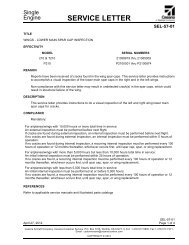
Figure 1. MLG Actuator Hydraulic Lines Inspection (Sheet 1)SEB07-3Page 6 April 16, 2007
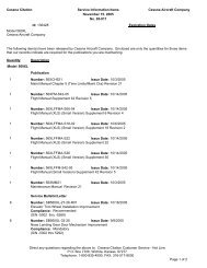
Figure 1. MLG Actuator Hydraulic Lines Inspection (Sheet 2)SEB07-3April 16, 2007 Page 7
CREDITNot applicableOWNER NOTIFICATIONOn April 30, 2007 the following Owner Advisory message will be sent to applicable owners of record inSEB07-3A.Dear <strong>Cessna</strong> Owner:This Owner Advisory is to inform you that SEB07-3: Main Landing Gear Actuator Hydraulic Lines Inspectionhas been issued.A report was received of attach screws being installed incorrectly on the main landing gear (MLG) actuatoraccess panel. The incorrectly installed attach screws caused wear and damage to a MLG hydraulic actuatorline located under the access panel. This <strong>Service</strong> <strong>Bulletin</strong> provides an inspection of the access panel attachscrews and the hydraulic lines. Non-compliance with this <strong>Service</strong> <strong>Bulletin</strong> could result in possible damage tothe MLG hydraulic actuator lines and the potential to loose hydraulic pressure to the MLG actuator.Compliance is recommended: should be accomplished within the next 100 hours of operation or during thenext scheduled 100 hour or annual/12 month type inspection, whichever occurs first.The information contained in the referenced <strong>Cessna</strong> <strong>Service</strong> <strong>Bulletin</strong> shall be considered an amendment tothe <strong>Cessna</strong> Manufacturer’s <strong>Service</strong>/Maintenance Manual and should be accomplished within the specifiedtime requirement.Please contact a <strong>Cessna</strong> Single Engine <strong>Service</strong> Station for detailed information and arrange to have <strong>Cessna</strong><strong>Service</strong> <strong>Bulletin</strong> SEB07-3 accomplished on your airplane.* * * * * * *SEB07-3Page 8 April 16, 2007