service letter - Cessna
service letter - Cessna
service letter - Cessna
- No tags were found...

You also want an ePaper? Increase the reach of your titles
YUMPU automatically turns print PDFs into web optimized ePapers that Google loves.
Multi-engineSERVICE LETTERMEL-24-02MATERIAL INFORMATIONNEW P/NINSTALLATIONINSTRUC-TIONSP52-0016 SK337-74 Contactor Kit, 24VIntermittent DutyX61-0030 Not Required/DirectReplacementKEY WORD OLD P/N INSTRUCTIONS/DISPOSITIONContactor, 12VIntermittent DutyP52-0033 LSI-018, Rev A Contactor Kit, 12VIntermittent DutyP52-0034 LSI-018, Rev A Contactor Kit, 12VContinuous DutyP52-0034-1 LSI-017, Rev A Contactor Kit, 12VContinuous DutyP52-0035-1 LSI-017, Rev A Contactor Kit, 24VContinuous DutyS1577-1, S1577A1,8781-8S2103-1, S2103A1,111-139DS1991-1, S1991A1,111-138D, SAW4204-1,SAW4206-1S1660-1, S1660A1,8781-10S1579-1, S1579-2,S1579A2/111-140DS1580-1, S1580A1,8781-9DiscardDiscardDiscardDiscardDiscardDiscardMEL-24-02Page 2 April 4, 2013
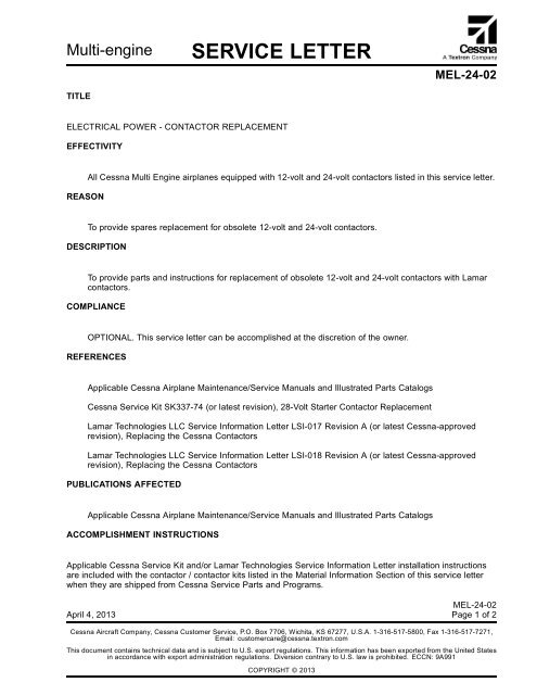
Multi-engineOWNER ADVISORYMEL-24-02TITLEELECTRICAL POWER - CONTACTOR REPLACEMENTTO:<strong>Cessna</strong> Multi Engine OwnerREASONThis owner advisory is to inform you that MEL-24-02 has been issued.MEL-24-02 provides spares replacement for obsolete 12-volt and 24-volt contactors.MEL-24-02 provides parts and instructions for replacement of obsolete 12-volt and 24-volt contactorswith Lamar contactors.COMPLIANCEOPTIONAL. This <strong>service</strong> <strong>letter</strong> can be accomplished at the discretion of the owner.LABOR HOURSNot applicableWARRANTYNot ApplicableNOTE: As a convenience, <strong>service</strong> documents are now available online to all our customers through asimple, free-of-charge registration process. If you would like to sign up, please visit the "CustomerAccess" link at www.cessnasupport.com to register.This owner advisory will not be mailed to airplane owners. It is provided as an attachment to this <strong>service</strong> <strong>letter</strong>.Month Dd, 2013MEL-24-02Page1of1<strong>Cessna</strong> Aircraft Company, <strong>Cessna</strong> Customer Service, P.O. Box 7706, Wichita, KS 67277, U.S.A. 1-316-517-5800, Fax 1-316-517-7271,Email: customercare@cessna.textron.comThis document contains technical data and is subject to U.S. export regulations. This information has been exported from the United Statesin accordance with export administration regulations. Diversion contrary to U.S. law is prohibited. ECCN: 9A991COPYRIGHT © 2013
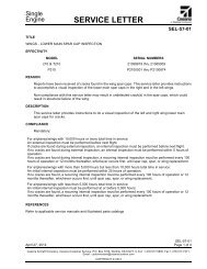
Multi-engineSERVICE KITSK337-74TITLE28-VOLT STARTER CONTACTOR REPLACEMENTEFFECTIVITYModel Year Serial Numbers337 1965 337-0002 thru 337-0239337A 1966 337-0240 thru 337-0305337A 1966 337-0307 thru 337-0469337A 1966 337-0471 thru 337-0525337B/T337B 1967 337-0526 thru 337-0568337B/T337B 1967 337-0570 thru 337-0755337B/T337B 337-0001, 337-0470337C/T337C 1968 337-0756 thru 337-0978337D/T337D 1969 337-0979 thru 337-1193337E/T337E 1970 33701194 thru 33701316337F/T337F 1971 33701317 thru 33701398T337F 33700569337F 1972 33701399 thru 33701448337F 1972 33701450 thru 33701462337F 33700306337G 1973 33701463 thru 33701550337G 1974 33701551 thru 33701606337G 1975 33701607 thru 33701671337G 1976 33701672 thru 33701748337G 1977 33701749 thru 33701815337G 33701449337H/T337H 1978 33701816 thru 33701853337H/T337H 1978 33701855 thru 33701874337H/T337H 1979 33701875 thru 33701908337H/T337H 33701854F337E/FT337E 1970 F33700001 thru F33700024April 17, 2006 Page 1 of 5To obtain satisfactory results, procedures specified in this publication must be accomplished in accordance with accepted methods andprevailing government regulations. <strong>Cessna</strong> Aircraft Company cannot be responsible for the quality of work performed in accomplishing therequirements of this publication.<strong>Cessna</strong> Aircraft Company, Product Support, P.O. Box 7706, Wichita, Kansas 67277, U.S.A. (316) 517-5800, Facsimile (316) 942-9006COPYRIGHT © 2006
SERVICE KITSK337-74F337E/FT337E 1971 F33700025 thru F33700045F337E/FT337E 1972 F33700046 thru F33700055F337G 1973 F33700056 thru F33700063F337G 1974 F33700064 thru F33700071F337G 1975 F33700072 thru F33700076F337G 1976 F33700077 thru F33700079F337G 1977 F33700080 thru F33700084F337H 1978 F33700085 thru F33700086FT337GP 1973 FP33700001 thru FP33700008FT337GP 1974 FP33700009 thru FP33700013FT337GP 1975 FP33700014 thru FP33700015FT337GP 1976 FP33700016 thru FP33700017FT337GP 1977 FP33700018 thru FP33700022FT337HP 1978 FP33700023P337H 1978 P3370293 thru P3370318P337H 1979 P3370319 thru P3370341T337G 1973 P3370001 thru P3370148T337G 1974 P3370149 thru P3370193T337G 1975 P3370194 thru P3370195T337G 1975 P3370197 thru P3370225T337G 1976 P3370226 thru P3370257T337G 1977 P3370258 thru P3370292DESCRIPTIONTo provide a spares replacement for the 28-volt starter contactor.APPROVALFAA approval has been obtained on technical data in this publication that affects airplane type design.For Reims Aviation Airplanes: DGAC approval has not been obtained on technical data in this publication. Theaffected "F" model and serial number airplanes are included for informational purposes. DGAC approval mustbe obtained for Reims airplanes prior to installation.CHANGE IN WEIGHT AND BALANCENegligiblePage 2SK337-74
SERVICE KITSK337-74MATERIAL INFORMATIONThe parts below cover installation for one airplane.NEW P/N QUANTITY DESCRIPTION OLD P/N DISPOSITIONSK337-74 1 Kit, consisting of thefollowing parts:P52-0016 2 28-Volt Starter Contactor S1577-1,S1577A1,8781-8Discard1 InstructionsACCOMPLISHMENT INSTRUCTIONS1. Prepare the airplane for maintenance.A. Make sure that all switches are in the OFF/NORM position.B. Remove the upper left engine cowl.C. Disconnect electrical power from the airplane.(1) Disconnect the airplane battery.(2) Disconnect external electrical power.D. Attach maintenance warning tags to the battery and external power receptacle that have "DO NOTCONNECT ELECTRICAL POWER - MAINTENANCE IN PROGRESS" writtenonthem.CAUTION: Do not use the P52-0016 28-Volt Starter Contactor to replace contactors in the airplaneother than those in the starter system. If you replace a contactor other than a startercontactor with the P52-0016 28-Volt Starter Contactor, damage to the equipment will occur.2. Get access to the 28-volt starter contactors on the left side of the forward engine firewall. (Refer tothe applicable sections of the Service Manual.)NOTE: To find the contactors, you can follow the starter power cable from the starter to the contactor.3. (Refer to Figure 1.) Remove and discard the 28-volt starter contactors. Keep the attaching hardware.(Refer to the applicable sections of the Service Manual.)4. With the kept attaching hardware, install the two new P52-0016 28-Volt Starter Contactors. (Refer tothe applicable sections of the Service Manual.)CAUTION: Make sure that you install the wires to the same contactor mount bolts as shown inFigure 1. If you install the wires in a different configuration than the one shown inFigure 1, damage to the contactor and the equipment will occur.A. As you install each of the two contactors, install the loose end of the ground wire that is attached tothe contactor under one of the contactor mount bolts to provide a ground for the contactor coil.CAUTION: If the airplane has a diode wire, do not replace the diode wire with a standard groundwire. If you replace the diode wire with a standard ground wire, damage to the startercontactor will occur.CAUTION: If the airplane has a diode wire, do not install the diode wire on the same connectorstud with the ground wire. If you install the diode wire and the ground stud wire on thesame connector stud, damage to the starter contactor will occur.B. If the airplane has a diode wire, install it on the new starter contactor. But, install it on a differentconnector stud then the one on which the ground stud wire is installed.SK337-74Page 3
SERVICE KITSK337-745. Install the upper left engine cowl.6. Remove maintenance warning tags and connect the airplane battery.7. Make an entry in the airplane logbook stating this <strong>service</strong> kit has been installed.Page 4SK337-74
SERVICE KITSK337-74Figure 1. 28-Volt Starter Contactor Replacement (Sheet 1)SK337-74Page 5
<strong>Cessna</strong> Aircraft Company Proprietary InformationCONTACTOR KITSIssued: 1/17/2013SERVICE INFORMATION LETTERREPLACING THE CESSNA CONTACTORSSUBJECT: This <strong>letter</strong> is to provide wiring installation instructions for Lamar P/N P52-0034-1 (12VContactor kit) and Lamar P/N P52-0035-1 (24V Contactor kit) as a replacement for the<strong>Cessna</strong> P/N S1579 (12V) and S1580 (24V) contactors. These instructions shall be printedand distributed in the packaging with each contactor kit.REASON:To provide clarification of contactor terminal definition for installing on aircraft.INFORMATION: Reference Figure shown below. The Lamar contactor kit will come with a red jumper wireinstalled from the Battery Terminal to the Coil Power Terminal. This jumper shall convert a4 terminal contactor for replacement of a 3 terminal contactor. 3 terminal contactors (S1579and S1580) have this connection inside the contactor without a coil power terminal. Aircraftwiring must control (on or off) the contactor coil through the Coil Ground Terminal and nothave any wires (except jumper) attached to the Coil Power Terminal.For technical support call <strong>Cessna</strong> Customer Care at 316-517-5800FIGURE:Coil Power Terminal(DO NOT connectaircraft wires here)Coil GroundTerminalBatteryTerminalLoadTerminalRedJumperWireLSI-017 REV: A RELEASE DATE: 1/17/13 PAGE 1 OF 1Printed On 02/06/2013
<strong>Cessna</strong> Aircraft Company Proprietary InformationCONTACTOR KITSIssued: 1/17/2013SERVICE INFORMATION LETTERREPLACING THE CESSNA CONTACTORSSUBJECT: This <strong>letter</strong> is to provide wiring installation instructions for Lamar P/N P52-0033 (12VIntermittent Duty Contactor kit) and Lamar P/N P52-0034 (12V Continuous Duty Contactorkit) as a replacement for the <strong>Cessna</strong> P/N S1991 (Intermittent Duty) and S1660 (ContinuousDuty) contactors. These instructions shall be printed and distributed in the packaging witheach contactor kit.REASON:To provide clarification of contactor terminal definition for installing on aircraft.INFORMATION: Reference Figure shown below. The Lamar contactor kit will come with a black jumper wirewith one end installed on the Coil Ground Terminal. This jumper when connected to theairframe ground (as shown) shall convert a 4 terminal contactor for replacement of a 3terminal contactor. 3 terminal contactors (S1991 and S1660) have this connection insidethe contactor without a Coil Ground Terminal. Aircraft wiring must control (on or off) thecontactor coil through the Coil Power Terminal and not have any wires (except jumper)attached to the Coil Ground Terminal.For technical support call <strong>Cessna</strong> Customer Care at 316-517-5800FIGURE:Coil Ground Terminal(do not connectaircraft wires here)Coil PowerTerminalBatteryTerminalLoadTerminalBlackJumperWireLSI-018 REV: A RELEASE DATE: 1/17/13 PAGE 1 OF 1Printed On 02/06/2013