Model 162 - Cessna
Model 162 - Cessna
Model 162 - Cessna

You also want an ePaper? Increase the reach of your titles
YUMPU automatically turns print PDFs into web optimized ePapers that Google loves.
CESSNAMODEL <strong>162</strong>GARMIN G300INTRODUCTIONPILOT’S OPERATING HANDBOOKANDFLIGHT TRAINING SUPPLEMENTCESSNA MODEL <strong>162</strong>SERIALS<strong>162</strong>00001 AND ONORIGINAL ISSUE - 22 JULY 2009REVISION 4 - 21 OCTOBER 2011PART NUMBER: <strong>162</strong>PHUS-04<strong>162</strong>PHUS-04U.S.i/ii
CESSNAMODEL <strong>162</strong>GARMIN G300CONGRATULATIONSINTRODUCTIONCongratulations on your purchase and welcome to <strong>Cessna</strong> ownership!Your <strong>Cessna</strong> has been designed and constructed to give you the mostin performance, value and comfort.This Pilot’s Operating Handbook has been prepared as a guide to helpyou get the most utility from your airplane. It contains information aboutyour airplane’s equipment, operating procedures, performance andsuggested service and care. Please study it carefully and use it as areference.The worldwide <strong>Cessna</strong> Organization and <strong>Cessna</strong> Customer Serviceare prepared to serve you. The following services are offered by each<strong>Cessna</strong> Service Station:• THE CESSNA AIRPLANE WARRANTIES, which provide coveragefor parts and labor, are upheld through <strong>Cessna</strong> Service Stationsworldwide. Warranty provisions and other important information arecontained in the Customer Care Handbook supplied with yourairplane. The Customer Care Card assigned to you at delivery willestablish your eligibility under warranty and should be presented toyour local <strong>Cessna</strong> Service Station at the time of warranty service.• FACTORY TRAINED PERSONNEL to provide you with courteous,expert service.• FACTORY APPROVED SERVICE EQUIPMENT to provide youefficient and accurate workmanship.• A STOCK OF GENUINE CESSNA SERVICE PARTS are availablewhen you need them.• THE LATEST AUTHORITATIVE INFORMATION FOR SERVICINGCESSNA AIRPLANES. <strong>Cessna</strong> Service Stations have all of thecurrent Maintenance Manuals, Illustrated Parts Catalogs andvarious other support publications produced by <strong>Cessna</strong> AircraftCompany.A <strong>Cessna</strong> Service Station locator is available atwww.cessnasupport.com.We urge all <strong>Cessna</strong> owners/operators to utilize the benefits availablewithin the <strong>Cessna</strong> Organization.<strong>162</strong>PHUS-01U.S.iii
INTRODUCTIONPERFORMANCE - SPECIFICATIONSCESSNAMODEL <strong>162</strong>GARMIN G300*SPEED:Maximum at Sea Level . . . . . . . . . . . . . . 118 KNOTS (218.5 km/hr)Cruise, 69% Power at 6000 Feet. . . . . . . 109 KNOTS (201.9 km/hr)CRUISE: Recommended lean mixture with fuel allowance for enginestart, taxi, takeoff, climb and 30 minutes reserve.RANGE:69% Power at 6000 Feet . . . . . . . . . . . . . . . . . . . . . Range - 336 NM24 Gallons Usable Fuel . . . . . . . . . . . . . . . . . . . Time - 3.16 HOURSRATE OF CLIMB AT SEA LEVEL . . . . . . . . . . . 880 FPM (268.2 mpm)SERVICE CEILING . . . . . . . . . . . . . . . . . . . . 14,625 FEET (4457.7 m)TAKEOFF PERFORMANCE AT SEA LEVEL:Ground Roll . . . . . . . . . . . . . . . . . . . . . . . . . . . .640 FEET (195.1 m)Total Distance Over 50 Foot Obstacle . . . . . . . 1138 FEET (346.9 m)LANDING PERFORMANCE AT SEA LEVEL:Ground Roll . . . . . . . . . . . . . . . . . . . . . . . . . . . .671 FEET (204.6 m)Total Distance Over 50 Foot Obstacle . . . . . . .1369 FEET (417.3 m)STALL SPEED:Flaps UP, Power Idle . . . . . . . . . . . . . . . . . . . . . . . . . . . . . . 41 KIASFlaps FULL, Power Idle . . . . . . . . . . . . . . . . . . . . . . . . . . . . 37 KIASNOTE* Speed performance is shown for airplanes not equippedwith the optional wheel fairings. Airplanes equipped withoptional wheel fairings will notice an increase in speeds byapproximately 2 knots. There is a corresponding differencein range, while all other performance figures areunchanged when speed fairings are installed.The above performance figures are based on airplane weights at 1320pounds (598.7 kg), standard atmospheric conditions, level, hardsurfaceddry runways and no wind. They are calculated values derivedfrom flight tests conducted by <strong>Cessna</strong> Aircraft Company under carefullydocumented conditions and will vary with individual airplanes andnumerous factors affecting flight performance.(Continued Next Page)ivU.S.<strong>162</strong>PHUS-03
CESSNAMODEL <strong>162</strong>GARMIN G300INTRODUCTIONPERFORMANCE - SPECIFICATIONS (Continued)MAXIMUM WEIGHT:Ramp. . . . . . . . . . . . . . . . . . . . . . . . . . . . 1324 POUNDS (600.5 kg)Takeoff. . . . . . . . . . . . . . . . . . . . . . . . . . . 1320 POUNDS (598.7 kg)Landing . . . . . . . . . . . . . . . . . . . . . . . . . . 1320 POUNDS (598.7 kg)Maximum Empty Weight . . . . . . . . . . . . . . 894 POUNDS (405.5 kg)STANDARD EMPTY WEIGHT. . . . . . . . . . . . 834 POUNDS (378.3 kg)MAXIMUM USEFUL LOAD . . . . . . . . . . . . . . 490 POUNDS (222.3 kg)BAGGAGE ALLOWANCE . . . . . . . . . . . . . . . . 50 POUNDS (22.68 kg)WING LOADING . . . . . . . . . . . . . . . . . . . 11.0 lbs/sq. ft. (53.7 kg/sq m)POWER LOADING . . . . . . . . . . . . . . . . . . . . . . . . . . . . . . . 13.2 lbs/HPFUEL CAPACITY (Usable) . . . . . . . . . . . . . . . . . 24 GALLONS (90.8 l)OIL CAPACITY (Sump) . . . . . . . . . . . . . . . . . . . . . . 5 QUARTS (4.73 I)ENGINE: Teledyne Continental Motors . . . . . . . . . . . . . . . . . . . O-200D100 BHP at 2750 RPMPROPELLER:Fixed Pitch, Diameter . . . . . . . . . . . . . . . . . . . . 67 INCHES (1.70 m)<strong>162</strong>PHUS-04U.S.v
INTRODUCTIONCOVERAGECESSNAMODEL <strong>162</strong>GARMIN G300The Pilot’s Operating Handbook (POH) in the airplane at the time ofdelivery from <strong>Cessna</strong> Aircraft Company contains information applicableto the <strong>Model</strong> <strong>162</strong> airplanes by serial number and registration numbershown on the Title Page. This POH is applicable to <strong>Model</strong> <strong>162</strong>airplanes, Serials <strong>162</strong>00001 and On, equipped with Garmin G300Integrated Cockpit System. All information is based on data available atthe time of publication.This POH consists of nine sections that cover all operational aspects ofa standard equipped airplane. Section 9 contains the supplementswhich provide amended operating limitations, operating procedures,performance data and other necessary information for airplanesconducting special operations for both standard and optionalequipment installed in the airplane.Supplements are individual documents, and may be issued or revisedwithout regard to revision dates which apply to the POH itself. Thesesupplements contain a Log of Effective Pages, which should be used todetermine the status of each supplement.viU.S.<strong>162</strong>PHUS-04
CESSNAMODEL <strong>162</strong>GARMIN G300ORIGINAL ISSUE AND REVISIONSINTRODUCTIONThis Pilot’s Operating Handbook is comprised of the original issue andany subsequent revisions. To make sure that information in this manualis current, the revisions must be incorporated as they are issued. Asrevisions are issued, they will be noted in the Log of Effective Pages.The part number of this manual has also been designed to further aidthe owner/operator in determining the revision level of any POH. Referto the example below for a breakdown:<strong>162</strong> PHUS -00Revision Level (Original Issue)Manual (Pilot’s Operating Handbook, U.S.)(Serials <strong>162</strong>00001 and On)Airplane <strong>Model</strong> - (<strong>162</strong>)It is the responsibility of the owner to maintain this POH in a currentstatus when it is being used for operational purposes. Owners shouldcontact a <strong>Cessna</strong> Service Station whenever the revision status of theirPOH is in question.Revisions are distributed to owners of U.S. Registered aircraftaccording to FAA records at the time of revision issuance, and toInternationally Registered aircraft according to <strong>Cessna</strong> Owner Advisoryrecords at the time of issuance. Revisions should be read carefullyupon receipt and incorporated in this POH.<strong>162</strong>PHUS-00U.S.vii
INTRODUCTIONREVISION FILING INSTRUCTIONSCESSNAMODEL <strong>162</strong>GARMIN G300REGULAR REVISIONSPages to be removed or inserted in the Pilots’ Operating Handbook aredetermined by the Log of Effective Pages located in this section. Thislog contains the page number and revision level for each page withinthe POH. As revisions to the POH occur, the revision level on effectedpages is updated. When two pages display the same page number, thepage with the latest revision level shall be inserted into the POH. Therevision level on the Log Of Effective Pages shall also agree with therevision level of the page in question.TEMPORARY REVISIONSUnder limited circumstances, temporary revisions to the POH may beissued. These temporary revisions are to be filed in the applicablesection in accordance with filing instructions appearing on the first pageof the temporary revision.Temporary Revisions will remain current until they have either beenincorporated into the next POH revision or another temporary revisionhas been issued that supersedes that temporary revision. Eachtemporary revision is issued with a current List of Temporary Revisionsthat is to be inserted opposite the first page of the Log of EffectivePages in the front of the POH and will supersede any previously issuedList of Temporary Revisions. This list is used to track the status oftemporary revisions issued against this POH and is to be removed anddiscarded at the next revision to the POH. Removal of temporaryrevisions from the POH is accomplished per the removal instructionson each temporary revision.viiiU.S.<strong>162</strong>PHUS-00
CESSNAMODEL <strong>162</strong>GARMIN G300IDENTIFYING REVISED MATERIALINTRODUCTIONA bar will extend the full length of deleted, new, or revised text addedon new or previously existing pages. This bar will be located adjacent tothe applicable text in the margin on the left side of the page.A bar in the footer will indicate a revision to the header/footer, a newpage, format or spelling/grammar changes and/or that information hasslipped to or from that page.A bar located adjacent to the figure number in the margin on the leftside of the page will be used to indicate that the figure number only haschanged.An asterisk located at the end of a figure number will be used toindicate that an illustration has been revised or is all new material (Ex:Figure 3-4*).All revised pages will carry the revision number opposite the pagenumber on the applicable page. A list of revisions is located at thebeginning of the Log Of Effective Pages.<strong>162</strong>PHUS-00U.S.ix
INTRODUCTIONWARNINGS, CAUTIONS AND NOTESCESSNAMODEL <strong>162</strong>GARMIN G300Throughout the text, warnings, cautions and notes pertaining toairplane handling and operations are utilized. These adjuncts to the textare used to highlight or emphasize important points.WARNINGOPERATING PROCEDURES, TECHNIQUES, ETC.,WHICH CAN RESULT IN PERSONAL INJURY OR LOSSOF LIFE IF NOT CAREFULLY FOLLOWED.CAUTIONOPERATION PROCEDURES, TECHNIQUES, ETC.,WHICH CAN RESULT IN DAMAGE TO EQUIPMENT IFNOT CAREFULLY FOLLOWED.NOTEAn operating procedure, technique, etc., which isconsidered essential to emphasize.xU.S.<strong>162</strong>PHUS-00
CESSNAMODEL <strong>162</strong>GARMIN G300LOG OF EFFECTIVE PAGESINTRODUCTIONUse this page to determine the currency and applicability of your POH.Pages affected by the current revision are indicated by an asterisk (*)preceding the pages listed under the Page Number column.Revision Level Date of Issue Revision Level Date of IssueOriginal Issue 22 July 2009 Revision 3 28 September 2010Revision 1 2 November 2009 Revision 4 21 October 2011Revision 2 26 April 2010PageNumberPageStatusRevisionNumber* Title Revised 4* i/ii Revised 4iii Revised 1iv Revised 3* v thru vi Revised 4vii thru x Original 0* xi thru xv/xvi Revised 4* xvii/xviii Added 4* 1-1/1-2 Revised 41-3 thru 1-4 Revised 1* 1-5 Revised 41-6 thru 1-7 Original 0* 1-8 Revised 4* 1-9 thru 1-31/1-32 Added 4* 2-1/2-2 thru 2-20 Revised 4* 2-21/2-22 Added 4(Continued Next Page)<strong>162</strong>PHUS-04U.S.xi
INTRODUCTIONCESSNAMODEL <strong>162</strong>GARMIN G300LOG OF EFFECTIVE PAGES (Continued)PageNumberPageStatusRevisionNumber* 3-1 thru 3-40 Revised 4* 4-1 thru 4-46 Revised 4* 4-47 thru 4-49/4-50 Added 4* 5-1/5-2 Revised 45-3 thru 5-4 Revised 1* 5-5 thru 5-7 Revised 45-8 Revised 1* 5-9 thru 5-18 Revised 4* 6-1/6-2 thru 6-30 Revised 4* 7-1 thru 7-56 Revised 48-1 Original 08-2 thru 8-4 Revised 18-5 Revised 38-6 Revised 18-7 thru 8-8 Revised 38-9 Revised 18-10 Revised 3* 8-11 Revised 48-12 Original 08-13 Revised 1* 8-14 Revised 48-15 thru 8-17 Original 0* 8-18 Revised 48-19 thru 8-23 Revised 18-24 Revised 38-25/8-26 Revised 1(Continued Next Page)xiiU.S.<strong>162</strong>PHUS-04
CESSNAMODEL <strong>162</strong>GARMIN G300INTRODUCTIONLOG OF EFFECTIVE PAGES (Continued)PageNumberPageStatusRevisionNumber* 9-1/9-2 Revised 4* 10-1/10-2 Deleted 4<strong>162</strong>PHUS-04U.S.xiii/xiv
CESSNAMODEL <strong>162</strong>GARMIN G300SERVICE BULLETIN CONFIGURATION LISTINTRODUCTIONThe following is a list of Service Bulletins that are applicable to theoperation of the airplane, and have been incorporated into this manual.This list contains only those Service Bulletins that are currently active.Number Title Airplane SerialEffectivitySB10-52-01 Door Latch Modification <strong>162</strong>00002 thru<strong>162</strong>00007,<strong>162</strong>00009 thru<strong>162</strong>00020SB11-52-01 Cabin Door SecondaryLatch Installation<strong>162</strong>00002 thru<strong>162</strong>00240Revision IncorporatedIncorporated in Airplane44<strong>162</strong>PHUS-04U.S.xv/xvi
CESSNAMODEL <strong>162</strong>GARMIN G300TABLE OF CONTENTSINTRODUCTIONSECTIONGENERAL . . . . . . . . . . . . . . . . . . . . . . . . . . . . . . . . . .1LIMITATIONS . . . . . . . . . . . . . . . . . . . . . . . . . . . . . . . .2EMERGENCY PROCEDURES . . . . . . . . . . . . . . . . . .3NORMAL PROCEDURES . . . . . . . . . . . . . . . . . . . . . .4PERFORMANCE . . . . . . . . . . . . . . . . . . . . . . . . . . . . .5WEIGHT AND BALANCE/EQUIPMENT LIST . . . . . . .6AIRPLANE AND SYSTEM DESCRIPTION . . . . . . . . .7HANDLING, SERVICE AND MAINTENANCE . . . . . . .8SUPPLEMENTS . . . . . . . . . . . . . . . . . . . . . . . . . . . . .9<strong>162</strong>PHUS-04U.S.xvii/xviii
CESSNA SECTION 1MODEL <strong>162</strong>GENERALGARMIN G300GENERALTABLE OF CONTENTSPageThree View - Normal Ground Attitude . . . . . . . . . . . . . . . . . . . . . . . .1-3Introduction . . . . . . . . . . . . . . . . . . . . . . . . . . . . . . . . . . . . . . . . . . . .1-5Descriptive Data . . . . . . . . . . . . . . . . . . . . . . . . . . . . . . . . . . . . . . . .1-5Engine . . . . . . . . . . . . . . . . . . . . . . . . . . . . . . . . . . . . . . . . . . . . . .1-5Propeller . . . . . . . . . . . . . . . . . . . . . . . . . . . . . . . . . . . . . . . . . . . .1-5Fuel . . . . . . . . . . . . . . . . . . . . . . . . . . . . . . . . . . . . . . . . . . . . . . . .1-6Fuel Capacity . . . . . . . . . . . . . . . . . . . . . . . . . . . . . . . . . . . . . . . .1-6Oil . . . . . . . . . . . . . . . . . . . . . . . . . . . . . . . . . . . . . . . . . . . . . . . . .1-7Oil Specification. . . . . . . . . . . . . . . . . . . . . . . . . . . . . . . . . . . . . . .1-7Oil Capacity. . . . . . . . . . . . . . . . . . . . . . . . . . . . . . . . . . . . . . . . . .1-7Maximum Certificated Weights . . . . . . . . . . . . . . . . . . . . . . . . . . .1-8Maximum Weight In Baggage Compartment . . . . . . . . . . . . . . . .1-8Standard Airplane Weights . . . . . . . . . . . . . . . . . . . . . . . . . . . . . .1-8Cabin And Entry Dimensions . . . . . . . . . . . . . . . . . . . . . . . . . . . .1-8Baggage Space And Entry Dimensions . . . . . . . . . . . . . . . . . . . .1-8Specific Loadings . . . . . . . . . . . . . . . . . . . . . . . . . . . . . . . . . . . . .1-8Symbols, Abbreviations And Terminology . . . . . . . . . . . . . . . . . . . . .1-9General Airspeed Terminology And Symbols . . . . . . . . . . . . . . . .1-9Meteorological Terminology . . . . . . . . . . . . . . . . . . . . . . . . . . . . 1-11Engine Power Terminology . . . . . . . . . . . . . . . . . . . . . . . . . . . . . 1-11Airplane Performance And Flight Planning Terminology. . . . . . .1-13Weight And Balance Terminology . . . . . . . . . . . . . . . . . . . . . . . .1-14Electrical and Avionics Terminology . . . . . . . . . . . . . . . . . . . . . .1-16Metric/Imperial/U.S. Conversion Charts. . . . . . . . . . . . . . . . . . . . . .1-17Weight Conversions . . . . . . . . . . . . . . . . . . . . . . . . . . . . . . . . . .1-18Length Conversions . . . . . . . . . . . . . . . . . . . . . . . . . . . . . . . . . .1-20Distance Conversions . . . . . . . . . . . . . . . . . . . . . . . . . . . . . . . . .1-24Volume Conversions . . . . . . . . . . . . . . . . . . . . . . . . . . . . . . . . . .1-25Temperature Conversions . . . . . . . . . . . . . . . . . . . . . . . . . . . . . .1-28Pressure Conversion. . . . . . . . . . . . . . . . . . . . . . . . . . . . . . . . . .1-29Volume To Weight Conversion . . . . . . . . . . . . . . . . . . . . . . . . . .1-30Quick Conversions . . . . . . . . . . . . . . . . . . . . . . . . . . . . . . .1-31/1-32<strong>162</strong>PHUS-04 U.S. 1-1/1-2
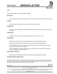
CESSNA SECTION 1MODEL <strong>162</strong>GENERALGARMIN G300THREE VIEW - NORMAL GROUND ATTITUDEFigure 1-1* (Sheet 1 of 2)<strong>162</strong>PHUS-01 U.S.1-3
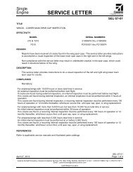
SECTION 1CESSNAGENERAL MODEL <strong>162</strong>GARMIN G300THREE VIEW - NORMAL GROUND ATTITUDENOTE• Wing span shown with standard strobe lights installed.• Wheel base length is 62.40 inches (1.58 m).• Propeller ground clearance is 8.50 inches (215.90 mm).• Wing area is 120.0 square feet (11.15 sq. m).Figure 1-1* (Sheet 2)1-4U.S.<strong>162</strong>PHUS-01
CESSNA SECTION 1MODEL <strong>162</strong>GENERALGARMIN G300INTRODUCTIONThis POH contains 9 sections, and includes the material required to befurnished to the pilot by American Society for Testing and MaterialsInternational (ASTM) standards F2245 for Light Sport Aircraft (LSA). Italso contains supplemental data supplied by <strong>Cessna</strong> Aircraft Company.Section 1 provides basic data and information of general interest. Italso contains definitions or explanations of symbols, abbreviations, andterminology commonly used.DESCRIPTIVE DATAENGINENumber of Engines: 1Engine Manufacturer: Teledyne Continental MotorsEngine <strong>Model</strong> Number: O-200-DEngine Type: Normally aspirated, direct drive, air-cooled, horizontallyopposed, carburetor equipped, four cylinder engine with201.0 cu. in. displacement.Horsepower Rating and Engine Speed: 100 rated BHP at 2750 RPMPROPELLERPropeller Manufacturer: McCauley Propeller SystemsPropeller <strong>Model</strong> Number:Standard Composite Propeller - 1L100/LSA6754Optional Aluminum Propeller - 1A<strong>162</strong>/TCD6754Number of Blades: 2Propeller Diameter: 67 inches (1.70 m)Propeller Type: Fixed Pitch(Continued Next Page)<strong>162</strong>PHUS-04 U.S.1-5
SECTION 1CESSNAGENERAL MODEL <strong>162</strong>GARMIN G300DESCRIPTIVE DATA (Continued)FUELWARNINGUSE OF UNAPPROVED FUELS MAY RESULT INDAMAGE TO THE ENGINE AND FUEL SYSTEMCOMPONENTS, RESULTING IN POSSIBLE ENGINEFAILURE.Approved Fuel Grades (and Colors):100LL Grade Aviation Fuel (Blue)100 Grade Aviation Fuel (Green)NOTEIsopropyl alcohol or Diethylene Glycol Monomethyl Ether(DiEGME) may be added to the fuel supply in accordanceto TCM Service Information Letter (SIL99-2B). Refer toSection 8 for additional information.FUEL CAPACITYTotal Capacity . . . . . . . . . . . . . . . . . 25.46 U.S. GALLONS (96.34 l)Total Usable . . . . . . . . . . . . . . . . . . . 24.00 U.S. GALLONS (90.82 l)Total Capacity Each Tank . . . . . . . . 12.73 U.S. GALLONS (48.17 l)Total Usable Each Tank . . . . . . . . . . 12.00 U.S. GALLONS (45.41 l)NOTE• To ensure maximum fuel capacity and minimizecrossfeeding when refueling, always park the airplane ina wings level, normal ground attitude. Refer to Figure 1-1 for normal ground attitude dimensions.• The fuel filler assembly is equipped with indicator tabsfor 3/4, 1/2 and 1/4 fuel quantities.• Maximum full capacity is indicated when fuel reaches theupper hole of the indicator tab. This fuel level allows forproper thermal expansion. Filling the fuel tank above theupper hole eliminates expansion space resulting in fuelventing overboard through the fuel vent.(Continued Next Page)1-6U.S.<strong>162</strong>PHUS-00
CESSNA SECTION 1MODEL <strong>162</strong>GENERALGARMIN G300DESCRIPTIVE DATA (Continued)OILOIL SPECIFICATIONSAE J1966 Aviation Grade Non-Dispersant Mineral Oil: Used when theairplane was delivered from the factory and should be used to replenishthe supply during the first 25 hours. This oil should be drained and thefilter changed after the first 25 hours of operation. Refill the engine withSAE J1966 Aviation Grade Non-Dispersant Mineral Oil and continue touse until a total of 50 hours has accumulated or oil consumption hasstabilized.SAE J1899 Aviation Grade Ashless Dispersant Oil: Oil conforming toTeledyne Continental Motors (TCM) Service Information Letter SIL99-2B, and all revisions and supplements thereto, must be used after first50 hours or oil consumption has stabilized.RECOMMENDED VISCOSITY FOR TEMPERATURE RANGEMultiviscosity or straight grade oil may be used throughout the year forengine lubrication. Refer to the following table for temperature versusviscosity ranges.SAE J1966Non-DispersantMineral OilSAE J1899Ashless Dispersant OilSAE GradeTemperature SAE GradeAbove 4°C (40°F) 50 50 or 15W-50 or 25W-60Below 4°C (40°F) 30 30 or 15W-50 or 25W-60All Temperatures M20W-50 15W-50, 20W- 50 or 25W-60NOTEWhen operating temperatures overlap, use the lightergrade of oil.OIL CAPACITYSump. . . . . . . . . . . . . . . . . . . . . . . . . . . . . 5.0 U.S. QUARTS (4.73 l)Total. . . . . . . . . . . . . . . . . . . . . . . . . . . . . . 5.5 U.S. QUARTS (5.20 l)Minimum Operating Quantity . . . . . . . . . .3.5 U.S. QUARTS (3.31 l)(Continued Next Page)<strong>162</strong>PHUS-00 U.S.1-7
SECTION 1CESSNAGENERAL MODEL <strong>162</strong>GARMIN G300DESCRIPTIVE DATA (Continued)MAXIMUM CERTIFICATED WEIGHTSRamp Weight:. . . . . . . . . . . . . . . . . . . . . . . . 1324 POUNDS (600.6 kg)Takeoff Weight . . . . . . . . . . . . . . . . . . . . . . . 1320 POUNDS (598.8 kg)Landing Weight . . . . . . . . . . . . . . . . . . . . . . 1320 POUNDS (598.8 kg)Maximum Empty Weight . . . . . . . . . . . . . . . . 894 POUNDS (405.5 kg)MAXIMUM WEIGHT IN BAGGAGE COMPARTMENTBaggage Area (Station 155 to 190) . . . . . . . . . 50 POUNDS (22.68 kg)STANDARD AIRPLANE WEIGHTSStandard Empty Weight . . . . . . . . . . . . . . . . . 834 POUNDS (378.3 kg)Maximum Useful Load . . . . . . . . . . . . . . . . . . 490 POUNDS (222.3 kg)CABIN AND ENTRY DIMENSIONSDetailed dimensions of the cabin interior and entry door openings areillustrated in Section 6.BAGGAGE SPACE AND ENTRY DIMENSIONSDimensions of the baggage area are illustrated in detail in Section 6.SPECIFIC LOADINGSWing Loading . . . . . . . . . . . . . . . . . . . . . 11.0 lbs/sq. ft. (53.7 kg/sq. m)Power Loading . . . . . . . . . . . . . . . . . . . . . . . . . . . . . . . . . . .13.2 lbs/HP1-8U.S.<strong>162</strong>PHUS-04
CESSNA SECTION 1MODEL <strong>162</strong>GENERALGARMIN G300SYMBOLS, ABBREVIATIONS AND TERMINOLOGYGENERAL AIRSPEED TERMINOLOGY AND SYMBOLSKCASKIASKTASGSV AV OV FEKnots Calibrated Airspeed is indicated airspeed correctedfor position and instrument error and expressed in knots.Knots calibrated airspeed is equal to KTAS in standardatmosphere at sea level.Knots Indicated Airspeed is the speed shown on theairspeed indicator and expressed in knots.Knots True Airspeed is the airspeed expressed in knotsrelative to undisturbed air which is KCAS corrected foraltitude and temperature.Ground Speed is the speed of an aircraft relative to theground.Design Maneuvering Speed is the maximum speed atwhich full or abrupt control movements may be used. Doesnot protect from possible overstressing the airframe.Maximum Operating Maneuvering Speed is the maximumspeed the airplane maybe stalled without exceedingstructural limitations.Maximum Flap Extended Speed is the highest speedpermissible with wing flaps in a prescribed extendedposition.(Continued Next Page)<strong>162</strong>PHUS-04 U.S.1-9
SECTION 1CESSNAGENERAL MODEL <strong>162</strong>GARMIN G300SYMBOLS, ABBREVIATIONS AND TERMINOLOGY(Continued)GENERAL AIRSPEED TERMINOLOGY AND SYMBOLS(Continued)V NOV NEV SV SOV xV YMaximum Structural Cruising Speed is the speed thatshould not be exceeded except in smooth air, then only withcaution.Never Exceed Speed is the speed limit that may not beexceeded at any time.Stalling Speed or the minimum steady flight speed is theminimum speed at which the airplane is controllable.Stalling Speed or the minimum steady flight speed is theminimum speed at which the airplane is controllable in thelanding configuration at the most forward center of gravity.Best Angle of Climb Speed is the speed which results inthe greatest gain of altitude in a given horizontal distance.Best Rate of Climb Speed is the speed which results in thegreatest gain in altitude in a given time.(Continued Next Page)1-10U.S.<strong>162</strong>PHUS-04
CESSNA SECTION 1MODEL <strong>162</strong>GENERALGARMIN G300SYMBOLS, ABBREVIATIONS AND TERMINOLOGY(Continued)METEOROLOGICAL TERMINOLOGYOATStandardTemperature(STD)PressureAltitude(PA)Outside Air Temperature is the free air statictemperature. It may be expressed in either degreesCelsius or degrees Fahrenheit.Standard Temperature is 15°C at sea level pressurealtitude and decreases by 2°C for each 1000 feet ofaltitude.Pressure Altitude is the altitude read from analtimeter when the altimeter's barometric scale hasbeen set to 29.92 inches of mercury (1013 mb).ENGINE POWER TERMINOLOGYMCPBHPRPMStatic RPMLeanMixtureMaximum Continuous Power is the maximum powerfor abnormal or emergency operations.Brake Horsepower is the power developed by theengine.Revolutions Per Minute is engine speed.Static RPM is engine speed attained during a fullthrottle engine runup when the airplane is on theground and stationary.Decreased proportion of fuel in the fuel-air mixturesupplied to the engine. As air density decreases, theamount of fuel required by the engine decreases for agiven throttle setting. Adjusting the fuel-air mixture toprovide a smaller portion of fuel is known as “leaning”the mixture.(Continued Next Page)<strong>162</strong>PHUS-04 U.S.1-11
SECTION 1CESSNAGENERAL MODEL <strong>162</strong>GARMIN G300SYMBOLS, ABBREVIATIONS AND TERMINOLOGY(Continued)ENGINE POWER TERMINOLOGY (Continued)RichMixtureFullRichIdleCutoffFullThrottleClosedThrottleCarb HeatOnCarb HeatOffFuel ShutoffOffFuel ShutoffOnIncreased proportion of fuel in the fuel-air mixturesupplied to the engine. As air density increases, theamount of fuel required by the engine increases for agiven throttle setting. Adjusting the fuel-air mixture toprovide a greater portion of fuel is known as “richening”the mixture.Mixture control full forward (pushed in, full controltravel, toward the panel).Mixture control full aft (pulled out, full control travel,away from the panel).Throttle full forward (pushed in, full control travel,toward the panel). Also known as “full open” throttle.Throttle full aft (pulled out, full control travel, away fromthe panel). Also known as the throttle “idle” position.Carburetor heat control knob full aft (pulled out, fullcontrol travel, away from the panel).Carburetor heat control knob full forward (pushed in,full control travel, toward the panel).Fuel shutoff valve knob full aft (pulled out, full controltravel, away from the panel).Fuel shutoff valve knob full forward (pushed in, fullcontrol travel, toward the panel).(Continued Next Page)1-12U.S.<strong>162</strong>PHUS-04
CESSNA SECTION 1MODEL <strong>162</strong>GENERALGARMIN G300SYMBOLS, ABBREVIATIONS AND TERMINOLOGY(Continued)AIRPLANE PERFORMANCE AND FLIGHT PLANNINGTERMINOLOGYDemonstratedCrosswindVelocityUsableFuelUnusableFuelGPHFPMgT/ODemonstrated Crosswind Velocity is the velocity ofthe crosswind component for which adequate controlof the airplane during takeoff and landing was actuallydemonstrated during certification tests. The valueshown is not considered to be limiting.Usable Fuel is the fuel available for flight planning.Unusable Fuel is the quantity of fuel that can not besafely used in flight.Gallons Per Hour is the amount of fuel consumed perhour.Feet Per Minute is the distance, in feet, traveled overthe duration of one minute.g is acceleration due to gravity.Takeoff(Continued Next Page)<strong>162</strong>PHUS-04 U.S.1-13
SECTION 1CESSNAGENERAL MODEL <strong>162</strong>GARMIN G300SYMBOLS, ABBREVIATIONS AND TERMINOLOGY(Continued)WEIGHT AND BALANCE TERMINOLOGYReferenceDatumF.S.W.L.ArmMomentCenter ofGravity(C.G.)C.G. ArmC.G. LimitsStandardEmpty WeightReference Datum is an imaginary vertical plane fromwhich all horizontal distances are measured forbalance purposes.Fuselage Station is a location along the airplanefuselage given in terms of the distance from thereference datum.Water Line is the intersection of an airplane exteriorprofile and a horizontal plane.Arm is the horizontal distance from the referencedatum to the center of gravity (C.G.) of an item.Moment is the product of the weight of an itemmultiplied by its arm. (Moment divided by the constant,1000 is used in this POH, to simplify balancecalculations by reducing the number of digits.)Center of Gravity is the point at which an airplane, orequipment, would balance if suspended. Its distancefrom the reference datum is found by dividing the totalmoment by the total weight of the airplane.Center of Gravity Arm is the arm obtained by addingthe airplane's individual moments and dividing the sumby the total weight.Center of Gravity Limits are the extreme center ofgravity locations within which the airplane must beoperated at a given weight.Standard Empty Weight is the weight of a standardairplane, including unusable fuel, full operating fluidsand full engine oil.(Continued Next Page)1-14U.S.<strong>162</strong>PHUS-04
CESSNA SECTION 1MODEL <strong>162</strong>GENERALGARMIN G300SYMBOLS, ABBREVIATIONS AND TERMINOLOGY(Continued)WEIGHT AND BALANCE TERMINOLOGY (Continued)Basic EmptyWeightMaximumEmpty WeightMaximumRamp WeightMaximumTakeoff WeightMaximumLandingWeightUseful LoadMinimumUseful LoadMACTareBasic Empty Weight is the standard empty weightplus the weight of optional equipment.Maximum Empty Weight is the difference betweenmaximum takeoff weight and minimum useful load.Maximum Ramp Weight is the maximum weightapproved for ground maneuver, and includes theweight of fuel used for start, taxi and runup.Maximum Takeoff Weight is the maximum weightapproved for the start of the takeoff roll.Maximum Landing Weight is the maximum weightapproved for the landing touchdown.Useful Load is the difference between ramp weightand the basic empty weight.Designed Minimum Useful Load is determined byASTM Regulations based on engine power.MAC (Mean Aerodynamic Chord) is a chord of animaginary rectangular airfoil having the same pitchingmoments throughout the flight range as that of theactual wing.Tare is the weight of chocks, blocks, stands, etc. usedwhen weighing an airplane, and is included in thescale readings. Tare is deducted from the scalereading to obtain the actual (net) airplane weight.<strong>162</strong>PHUS-04 U.S.1-15
SECTION 1CESSNAGENERAL MODEL <strong>162</strong>GARMIN G300SYMBOLS, ABBREVIATIONS AND TERMINOLOGY(Continued)ELECTRICAL AND AVIONICS TERMINOLOGYADAHRSAVNAUXPFDMFDELTA/PCBCAB PWREISGPSSEC PWRXPDRPTTALTBATTLDGHSIVHFNAVCOMCASBRSAirdata Attitude Heading Reference SystemAvionicsAuxiliaryPrimary Flight DisplayMulti-Functional DisplayEmergency Locator TransmitterAuto PilotCircuit BreakerCabin PowerEngine Indicating SystemGlobal Positioning SystemSecondary PowerTransponderPush-To-TalkAlternatorBatteryLandingHorizontal Situation IndicatorVery High FrequencyNavigationCommunicationCrew Alerting SystemBallistic Recovery System1-16U.S.<strong>162</strong>PHUS-04
CESSNA SECTION 1MODEL <strong>162</strong>GENERALGARMIN G300METRIC/IMPERIAL/U.S. CONVERSION CHARTSThe following charts have been provided to help international operatorsconvert U.S. measurement supplied with the Pilot’s OperatingHandbook into metric and imperial measurements.The standard followed for measurement units shown is the NationalInstitute of Standards Technology (NIST), Publication 811, “Guide forthe Use of the International System of Units (SI).”Please refer to the following pages for these charts.<strong>162</strong>PHUS-04 U.S.1-17
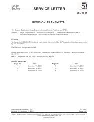
SECTION 1CESSNAGENERAL MODEL <strong>162</strong>GARMIN G300WEIGHT CONVERSIONSFigure 1-2* (Sheet 1 of 2)1-18U.S.<strong>162</strong>PHUS-04
CESSNA SECTION 1MODEL <strong>162</strong>GENERALGARMIN G300WEIGHT CONVERSIONSFigure 1-2* (Sheet 2)<strong>162</strong>PHUS-04 U.S.1-19
SECTION 1CESSNAGENERAL MODEL <strong>162</strong>GARMIN G300LENGTH CONVERSIONSFigure 1-3* (Sheet 1 of 4)1-20U.S.<strong>162</strong>PHUS-04
CESSNA SECTION 1MODEL <strong>162</strong>GENERALGARMIN G300LENGTH CONVERSIONSFigure 1-3* (Sheet 2)<strong>162</strong>PHUS-04 U.S.1-21
SECTION 1CESSNAGENERAL MODEL <strong>162</strong>GARMIN G300LENGTH CONVERSIONSFigure 1-3* (Sheet 3)1-22U.S.<strong>162</strong>PHUS-04
CESSNA SECTION 1MODEL <strong>162</strong>GENERALGARMIN G300LENGTH CONVERSIONSFigure 1-3* (Sheet 4)<strong>162</strong>PHUS-04 U.S.1-23
SECTION 1CESSNAGENERAL MODEL <strong>162</strong>GARMIN G300DISTANCE CONVERSIONSFigure 1-4*1-24U.S.<strong>162</strong>PHUS-04
CESSNA SECTION 1MODEL <strong>162</strong>GENERALGARMIN G300VOLUME CONVERSIONSFigure 1-5* (Sheet 1 of 3)<strong>162</strong>PHUS-04 U.S.1-25
SECTION 1CESSNAGENERAL MODEL <strong>162</strong>GARMIN G300VOLUME CONVERSIONSFigure 1-5* (Sheet 2)1-26U.S.<strong>162</strong>PHUS-04
CESSNA SECTION 1MODEL <strong>162</strong>GENERALGARMIN G300VOLUME CONVERSIONSFigure 1-5* (Sheet 3)<strong>162</strong>PHUS-04 U.S.1-27
SECTION 1CESSNAGENERAL MODEL <strong>162</strong>GARMIN G300TEMPERATURE CONVERSIONSFigure 1-6*1-28U.S.<strong>162</strong>PHUS-04
CESSNA SECTION 1MODEL <strong>162</strong>GENERALGARMIN G300PRESSURE CONVERSIONHECTOPASCALS TO INCHES OF MERCURYFigure 1-7*<strong>162</strong>PHUS-04 U.S.1-29
SECTION 1CESSNAGENERAL MODEL <strong>162</strong>GARMIN G300VOLUME TO WEIGHT CONVERSIONFigure 1-8*1-30U.S.<strong>162</strong>PHUS-04
CESSNA SECTION 1MODEL <strong>162</strong>GENERALGARMIN G300QUICK CONVERSIONSFigure 1-9*<strong>162</strong>PHUS-04 U.S. 1-31/1-32
CESSNA SECTION 2MODEL <strong>162</strong>OPERATING LIMITATIONSGARMIN G300OPERATING LIMITATIONSTABLE OF CONTENTSPageIntroduction . . . . . . . . . . . . . . . . . . . . . . . . . . . . . . . . . . . . . . . . . . . .2-3Airspeed Limitations . . . . . . . . . . . . . . . . . . . . . . . . . . . . . . . . . . . . .2-4Airspeed Indicator Markings . . . . . . . . . . . . . . . . . . . . . . . . . . . . . . .2-5Powerplant Limitations. . . . . . . . . . . . . . . . . . . . . . . . . . . . . . . . . . . .2-6Powerplant and Electrical Instrument Markings. . . . . . . . . . . . . . . . .2-7Weight Limits . . . . . . . . . . . . . . . . . . . . . . . . . . . . . . . . . . . . . . . . . . .2-8Maximum Weight in Baggage Compartment. . . . . . . . . . . . . . . . .2-8Center of Gravity Limits . . . . . . . . . . . . . . . . . . . . . . . . . . . . . . . . . . .2-8Service Ceiling. . . . . . . . . . . . . . . . . . . . . . . . . . . . . . . . . . . . . . . . . .2-8Maneuver Limits . . . . . . . . . . . . . . . . . . . . . . . . . . . . . . . . . . . . . . . .2-9Load Factors . . . . . . . . . . . . . . . . . . . . . . . . . . . . . . . . . . . . . . . . . . .2-9Flight Load Factor Limits. . . . . . . . . . . . . . . . . . . . . . . . . . . . . . . 2-9Kinds of Operations Limits. . . . . . . . . . . . . . . . . . . . . . . . . . . . . . . .2-10Kinds of Operations Equipment List . . . . . . . . . . . . . . . . . . . . . . . . 2-11Fuel Limitations . . . . . . . . . . . . . . . . . . . . . . . . . . . . . . . . . . . . . . . .2-14Flaps Limitations . . . . . . . . . . . . . . . . . . . . . . . . . . . . . . . . . . . . . . .2-14System Limitations. . . . . . . . . . . . . . . . . . . . . . . . . . . . . . . . . . . . . .2-1512V Power Outlet . . . . . . . . . . . . . . . . . . . . . . . . . . . . . . . . . . . .2-15G300 Limitations . . . . . . . . . . . . . . . . . . . . . . . . . . . . . . . . . . . . .2-15Placards. . . . . . . . . . . . . . . . . . . . . . . . . . . . . . . . . . . . . . . . . . . . . .2-16<strong>162</strong>PHUS-04 U.S. 2-1/2-2
CESSNA SECTION 2MODEL <strong>162</strong>OPERATING LIMITATIONSGARMIN G300INTRODUCTIONSection 2 includes operating limitations, instrument markings, andbasic placards necessary for the safe operation of the airplane, itsengine, standard systems and standard equipment. The limitationsincluded in this section and in Section 9 have been approved.Observance of these operating limitations is required by FederalAviation Regulations.NOTE• Refer to Section 9, Supplements, of this Pilot'sOperating Handbook for amended operating limitations,operating procedures, performance data and othernecessary information for airplanes equipped withspecific options.• The airspeeds listed in Figure 2-1, Airspeed Limitations,are based on Airspeed Calibration data shown in Section5.The <strong>Cessna</strong> <strong>Model</strong> No. <strong>162</strong> is approved under ASTM standard F2245.<strong>162</strong>PHUS-04 U.S.2-3
SECTION 2CESSNAOPERATING LIMITATIONS MODEL <strong>162</strong>GARMIN G300AIRSPEED LIMITATIONSAirspeed limitations and their operational significance are shown inFigure 2-1.AIRSPEED LIMITATIONSSYMBOL SPEED KCAS KIAS REMARKSV S Stall Speed - Clean 44 41 Stall speed flap up.V SOV FEV OV AStall Speed - LandingConfigurationMaximum FlapExtended Speed:FLAPS 10°FLAPS 25°FLAPS FULLMaximum OperatingManeuvering Speed1320 Pounds1200 Pounds1100 Pounds40 37 Stall speed flaps full9884718884811008570898580Design ManeuveringSpeed: 100 102Do not exceed this speedwith flaps down.Maximum speed at whichthe airplane may bestalled without exceedingstructural limitations.Do not make full or abruptcontrol movements abovethis speed.Does not provideprotection from possibleoverstressing the airplane.V NE Never Exceed Speed 143 148 Do not exceed this speedin any operation.V NOMaximum StructuralCruising Speed120 124 Do not exceed this speedexcept in smooth air, andthen only with caution.Figure 2-12-4U.S.<strong>162</strong>PHUS-04
CESSNA SECTION 2MODEL <strong>162</strong>OPERATING LIMITATIONSGARMIN G300AIRSPEED INDICATOR MARKINGSAirspeed indicator markings and their color code significance areshown in Figure 2-2.MARKINGAIRSPEED INDICATOR MARKINGSKIAS VALUE ORRANGERed Band 149 Maximum speed for all operations.Flaps 25°Tick MarkFlaps 10°Tick MarkVx TickMarkVy TickMark85 Maximum Flaps 25° Operation100 Maximum Flaps 10° Operation57 Best Angle of Climb Air Speed62 Best Rate of Climb Air SpeedFigure 2-2<strong>162</strong>PHUS-04 U.S.2-5
SECTION 2CESSNAOPERATING LIMITATIONS MODEL <strong>162</strong>GARMIN G300POWERPLANT LIMITATIONSEngine Manufacturer: Teledyne Continental MotorsEngine <strong>Model</strong> Number: O-200-DMaximum Power: 100 BHP RatingEngine Operating Limits for Takeoff and Continuous Operations:Maximum Engine Speed:. . . . . . . . . . . . . . . . . . . . . . . . . .2750 RPMNOTEThe static RPM range at full throttle with carburetor heat offand mixture leaned to maximum RPM is 2375 - 2475 RPM.For allowable variations in static RPM at non-standardtemperatures, refer to the <strong>162</strong> Maintenance Manual.Maximum Oil Temperature: . . . . . . . . . . . . . . . . . . . . .240°F (116°C)Oil Pressure, Minimum: . . . . . . . . . . . . . . . . . . . . . . . . . . . . . .10 PSIOil Pressure, Maximum: . . . . . . . . . . . . . . . . . . . . . . . . . . . .100 PSICAUTIONENGINE OPERATION WITH INDICATED OIL PRESSUREBELOW THE GREEN BAND RANGE WHILE IN CRUISEOR CLIMB CONFIGURATION IS CONSIDEREDABNORMAL. REFER TO SECTION 3, AMPLIFIEDEMERGENCY PROCEDURES, "LOW OIL PRESSURE".Fuel Grade: Refer to Fuel LimitationsOil Grade (Specification):SAE J1966 Aviation Grade Non-Dispersant Mineral Oil or SAEJ1899 Aviation Grade Ashless Dispersant Oil. Oil must comply withthe latest revision and/or supplement for Teledyne ContinentalMotors (TCM) Service Information Letter SIL99-2B or later revision,must be used.Propeller Manufacturer: McCauley Propeller SystemsStandard Composite Propeller <strong>Model</strong> Number. . . . . . . 1L100/LSA6754Maximum Propeller Diameter . . . . . . . . . . . . 67.0 INCHES (1.70 m)Minimum Propeller Diameter . . . . . . . . . . . . . 66.5 INCHES (1.69 m)Optional Aluminum Propeller <strong>Model</strong> Number . . . . . . . .1A<strong>162</strong>/TCD6754Maximum Propeller Diameter . . . . . . . . . . . . 67.0 INCHES (1.70 m)Minimum Propeller Diameter . . . . . . . . . . . . . 66.0 INCHES (1.68 m)2-6U.S.<strong>162</strong>PHUS-04
CESSNA SECTION 2MODEL <strong>162</strong>OPERATING LIMITATIONSGARMIN G300POWERPLANT AND ELECTRICAL INSTRUMENTMARKINGSPowerplant and electrical instrument markings and their color codesignificance are shown in Figure 2-3. Operation with indications in thered range is prohibited. Avoid operating with indicators in the yellowrange.POWERPLANT AND ELECTRICAL INSTRUMENT MARKINGSINSTRUMENTTachometer(RPM)OilTemperature(OIL °F)Oil Pressure(OIL PSI)Exhaust GasTemperature(if installed)(EGT °F)CarburetorTemperature(CARB °F)BatteryCurrent(AMPS)Bus Voltage(VOLTS)RED(LOWERWARNING)YELLOW(LOWERCAUTION)GREEN(NORMALOPERATINGRANGE)---- ---- 2000 to 2750RPMYELLOW(UPPERCAUTION)RED(UPPERWARNING)2750* to 3500RPM---- 0 to 75°F 75 to 220°F 220 to 240°F 240* to 265°F0 to 10 PSI 10 to 30 PSI 30 to 60 PSI 60 to 100 PSI 100* to 140 PSI---- ---- 1000 to 1600°FWhite Advisory5 to 40°F-35 to 35White Advisory-30 to 12.5 12.5 to 15 15 to 16 16 to 30*Maximum operating limit is lower end of red.Figure 2-3<strong>162</strong>PHUS-04 U.S.2-7
SECTION 2CESSNAOPERATING LIMITATIONS MODEL <strong>162</strong>GARMIN G300WEIGHT LIMITSMaximum Ramp Weight: . . . . . . . . . . . . . . . 1324 POUNDS (600.6 kg)Maximum Takeoff Weight . . . . . . . . . . . . . . . 1320 POUNDS (598.8 kg)Maximum Landing Weight . . . . . . . . . . . . . . 1320 POUNDS (598.8 kg)Maximum Empty Weight . . . . . . . . . . . . . . . . 894 POUNDS (405.5 kg)MAXIMUM WEIGHT IN BAGGAGE COMPARTMENTBaggage Area (Station 155 to 190) . . . . . . . . . 50 POUNDS (22.68 kg)WARNINGAFT BULKHEAD CLOSEOUT NET REQUIRED FORFLIGHT.NOTEMaximum baggage compartment loading must not exceed8 pounds per square foot.CENTER OF GRAVITY LIMITSCenter Of Gravity Range:Forward: 134.46 inches (3415.28 mm) aft of datum at 1320pounds (598.74 kg) or less, with straight line variationto 132.06 inches (3354.32 mm) aft of datum at 1050pounds (476.27 kg).Aft:136.86 inches (3476.24 mm) aft of datum at allweights.Reference Datum: Lower portion of front face of firewall.SERVICE CEILING: . . . . . . . . . . . . . . . . 14,625 Feet (4457.7 m)2-8U.S.<strong>162</strong>PHUS-04
CESSNA SECTION 2MODEL <strong>162</strong>OPERATING LIMITATIONSGARMIN G300MANEUVER LIMITSThis airplane is approved under ASTM standard F2245 and is intendedfor recreational and instructional flight operations. In the acquisition ofvarious pilot certificates certain maneuvers are required and thesemaneuvers are permitted in this airplane.MANEUVERS AND RECOMMENDED ENTRY SPEED*Chandelles . . . . . . . . . . . . . . . . . . . . . . . . . . . . . . . . . . . . .102 KIASLazy Eights . . . . . . . . . . . . . . . . . . . . . . . . . . . . . . . . . . . . .102 KIASSteep Turns. . . . . . . . . . . . . . . . . . . . . . . . . . . . . . . . . . . . .102 KIASStalls (Except Whip Stalls) . . . . . . . . . . . . . . . . . . Slow DecelerationPower On Stalls. . . . . . . . . . . . . . . . . . . . . . . . . . . Slow Deceleration(limit pitch to 30° nose up attitude)* Abrupt use of the controls is prohibited above 102 KIAS.WARNING• AEROBATIC MANEUVERS, INCLUDING SPINS, AREPROHIBITED.• INTENTIONAL FLIGHT WITH CABIN DOOR(S) OPENIS PROHIBITED.LOAD FACTORSFLIGHT LOAD FACTOR LIMITSFlight Load Factors (Maximum Takeoff Weight - 1320 POUNDS):Flaps UP: . . . . . . . . . . . . . . . . . . . . . . . . . . . . . . . . . . . .+4.0g, -2.0gFlaps FULL:. . . . . . . . . . . . . . . . . . . . . . . . . . . . . . . . . . . . . . . . +2.0g<strong>162</strong>PHUS-04 U.S.2-9
SECTION 2CESSNAOPERATING LIMITATIONS MODEL <strong>162</strong>GARMIN G300KINDS OF OPERATIONS LIMITSThe <strong>Cessna</strong> <strong>162</strong> airplane is approved for DAY - NIGHT - VFRoperations only. Flight into known icing conditions is prohibited.The minimum equipment for approved operations required under theOperating Rules are defined by 14 CFR 91 and ASTM standard F2245,as applicable.The following Kinds of Operations Equipment List (KOEL) identifies theequipment required to be operational for airplane airworthiness in thelisted kind of operations.2-10U.S.<strong>162</strong>PHUS-04
VFRCESSNA SECTION 2MODEL <strong>162</strong>OPERATING LIMITATIONSGARMIN G300KINDS OF OPERATIONS EQUIPMENT LISTKIND OFOPERATIONVFRNIGHTSystem, Instrument, Equipmentand/or FunctionPLACARDS AND MARKINGSDAYCOMMENTS1 - <strong>162</strong> POH/FTS - Garmin G300 0 0 Recommended to beaccessible to pilot inflight.2 - <strong>162</strong> Pilot’s Checklist 1 1 Required to beaccessible to pilot inflight.3 - Garmin G300 Pilot’s Guide 0 0 Recommended to beaccessible to pilot inflight.AIR CONDITIONING1 - Avionics Fan 1 1COMMUNICATIONS1 - VHF COM 0 0ELECTRICAL POWER1 - 12V Main Battery 1 12 - 14V Alternator 1 13 - Secondary Battery 0 14 - Ammeter 0 1EQUIPMENT AND FURNISHINGS1 - Seat Belt Assembly 1 1 Each Seat Occupant2 - Shoulder Harness 1 1 Each Seat Occupant3 - Aft Bulkhead Closeout Net 1 1FLIGHT CONTROLS1 - Elevator Trim System 1 12 - Elevator Trim Indicator 1 1(Continued Next Page)<strong>162</strong>PHUS-04 U.S.2-11
SECTION 2CESSNAOPERATING LIMITATIONS MODEL <strong>162</strong>GARMIN G300KINDS OF OPERATIONS EQUIPMENT LIST (Continued)System, Instrument, Equipment and/or FunctionFUEL SYSTEMKIND OFOPERATIONVFRDAYVFRNIGHT(Continued Next Page)COMMENTS1 - Fuel Shutoff Control Valve 1 12 - Cockpit Fuel Quantity Indicator - 1 1L Tank3 - Cockpit Fuel Quantity Indicator - 1 1R TankINDICATING/RECORDINGSYSTEM1 - Low Airspeed Alert and Stall 1 1Warning System2 - G300 System Annunciator and 1 1Warning DisplaysLANDING GEAR1 - Wheel Fairings 0 0 RemovableLIGHTING1 - PFD Bezel Lighting 0 02 - PFD Display Backlighting 1 13 - MFD Bezel Lighting (if installed) 0 04 - MFD Display Backlighting1 1(if installed)5 - Cockpit Overhead Panel Lighting 0 16 - Aircraft Position (NAV) Lights 0 17 - STROBE Light System 1 18 - LAND (Landing) Light 0 19 - Non-stabilized Magnetic0 0Compass Internal Lighting(if installed)2-12U.S.<strong>162</strong>PHUS-04
CESSNA SECTION 2MODEL <strong>162</strong>OPERATING LIMITATIONSGARMIN G300KINDS OF OPERATIONS EQUIPMENT LIST (Continued)System, Instrument, Equipment and/or FunctionKIND OFOPERATIONVFRDAYVFRNIGHTCOMMENTSNAVIGATION AND PITOT-STATIC SYSTEM1 - G300 Airspeed Indicator 1 12 - G300 Altimeter 1 13 - G300 Vertical Speed Indicator 0 04 - G300 Attitude Indicator 0 05 - G300 Directional Indicator (HSI) 0 06 - G300 Turn Coordinator 0 07 - G300 Magnetic Heading1 1Indicator8 - GPS Receiver/Navigator A/R A/R As RequiredProcedure.Per9 - GTX 327 Mode C Transponder A/R A/R As RequiredProcedure.Per10 - Blind Altitude Encoder A/R A/R As RequiredProcedure.Per11 - G300 Clock 0 012 - Magnetic Compass (if installed) 0 013 - Autopilot System 0 0ENGINE INDICATING1 - Tachometer (RPM) 1 12 - Carburetor Temperature Indicator 0 0(CARB °F)3 - Oil Pressure Indicator 1 14 - Oil Temperature Indicator 1 15 - Exhaust Gas Temperature (EGT)Indicator (if installed)0 0ENGINE OIL1 - Engine Crankcase Dipstick 1 1<strong>162</strong>PHUS-04 U.S.2-13
SECTION 2CESSNAOPERATING LIMITATIONS MODEL <strong>162</strong>GARMIN G300FUEL LIMITATIONSTotal Fuel: . . . . . . . . . . . . . . . . . . . . . . . . . . . . . .25.46 U.S. GALLONS(12.73 GALLONS per tank)Usable Fuel (all flight conditions): . . . . . . . . . . . . .24.0 U.S. GALLONS(12 GALLONS per tank)Unusable Fuel: . . . . . . . . . . . . . . . . . . . . . . . . . . . .1.46 U.S. GALLONS(0.73 GALLONS per tank)WARNINGTAKEOFF IS PROHIBITED IF EITHER SIGHT GAGEINDICATES LESS THAN ¼ TANK OF FUEL OR FUELLEVEL IS BELOW THE BOTTOM OF THE FUELINDICATOR TAB.GRNDMINT.O.MARKING ON FUEL INDICATORNOTETo ensure maximum fuel capacity and minimizecrossfeeding when refueling, always park the airplane in awings level, normal ground attitude. Refer to Figure 1-1 fornormal ground attitude definition.Fuel remaining in the tank after the fuel quantity indicator reads “E”cannot be safely used in flight.Approved Fuel Grades (And Colors):100LL Grade Aviation Fuel (Blue)100 Grade Aviation Fuel (Green)FLAP LIMITATIONSApproved Takeoff Range:. . . . . . . . . . . . . . . . . . . . . . . . . . . . UP to 10°Approved Landing Range: . . . . . . . . . . . . . . . . . . . . . . . . . .UP to FULL2-14U.S.<strong>162</strong>PHUS-04
CESSNA SECTION 2MODEL <strong>162</strong>OPERATING LIMITATIONSGARMIN G300SYSTEM LIMITATIONS12V POWER OUTLETThe 12 Volt Power Outlet (POWER OUTLET 12V - 7.5A) is not certifiedfor supplying power to flight-critical communications or navigationdevices.Use of the 12 Volt Power Outlet is prohibited during takeoff and landing.G300 LIMITATIONSNOTEIt is recommended that a current Garmin G300 Pilot’sGuide be available to the pilot during flight.Use of the MAP page for pilotage navigation is prohibited. Thenavigation map is intended only to enhance situational awareness.Navigation is to be conducted using only current charts, data andauthorized navigation facilities.Use of the TERRAIN information for primary terrain and obstacleavoidance is prohibited. The terrain map is intended only to enhancesituational awareness. It is the pilot’s responsibility to provide terrainclearance at all times.Navigation using the G300 is not authorized north of 70° North latitudeor south of 70° South latitude due to unsuitability of the magnetic fieldsnear the Earth's poles. In addition, operations are not authorized in thefollowing two regions:1. North of 65° North latitude between longitude 75° W and 120° W(Northern Canada).2. South of 55° South latitude between longitude 120° E and 165° E(region south of Australia and New Zealand).<strong>162</strong>PHUS-04 U.S.2-15
SECTION 2CESSNAOPERATING LIMITATIONS MODEL <strong>162</strong>GARMIN G300PLACARDSThe following information must be displayed in the form of composite orindividual placards.1. In full view of the pilot: (The DAY-NIGHT-VFR entry, shown onthe example below, will vary with installed equipment):The markings and placards installed in this airplane contain operatinglimitations which must be complied with when operating this airplane.Other operating limitations which must be complied with whenoperating this airplane in this category are contained in the Pilot’sOperating Handbook.No acrobatic maneuvers, including spins, are approved.Flight into known icing conditions prohibited.This airplane is approved for the following flight operations as of thedate of original airworthiness certificate:DAY - NIGHT - VFR2. On control lock:3. On left instrument panel above magnetos switch:TAKEOFF PROHIBITED WITH LESS THAN 1/4 FUELMINTO(Continued Next Page)2-16U.S.<strong>162</strong>PHUS-04
CESSNA SECTION 2MODEL <strong>162</strong>OPERATING LIMITATIONSGARMIN G300PLACARDS (Continued)4. On the lower left instrument panel:WARNINGAssure that all contaminants,including water, are removedfrom fuel and fuel systemsbefore flight. Failure to assurecontaminant free fuel and heedall safety instructions andowner advisories prior to flightcan result in bodily injury or death.5. On the upper left instrument panel:NO INTENTIONAL SPINS6. On the instrument panel directly above the PFD:MAXIMUM OPERATING MANEUVERING SPEED: 89 KIASDESIGN MANEUVERING SPEED: 102 KIAS7. On the upper right instrument panel:8. On the right instrument panel:This aircraft wasmanufactured inaccordance with LightSport Aircraft airworthinessstandards and does not conformto standard category airworthinessrequirements.(Continued Next Page)<strong>162</strong>PHUS-04 U.S.2-17
SECTION 2CESSNAOPERATING LIMITATIONS MODEL <strong>162</strong>GARMIN G300PLACARDS (Continued)9. On the right side of the baggage compartment below thewindow:10. Near both fuel tank filler caps:11. On the engine oil access door:(Continued Next Page)2-18U.S.<strong>162</strong>PHUS-04
CESSNA SECTION 2MODEL <strong>162</strong>OPERATING LIMITATIONSGARMIN G300PLACARDS (Continued)12. On firewall adjacent to battery box and second placard onexternal power receptacle door if external power receptacleoption is installed:13. Located on both left and right fuel sight tubes.(Continued Next Page)<strong>162</strong>PHUS-04 U.S.2-19
SECTION 2CESSNAOPERATING LIMITATIONS MODEL <strong>162</strong>GARMIN G300PLACARDS (Continued)14. Located adjacent to both exterior cabin door latch assemblies.15. Located adjacent to both primary interior cabin door latchassemblies.(Continued Next Page)2-20U.S.<strong>162</strong>PHUS-04
CESSNA SECTION 2MODEL <strong>162</strong>OPERATING LIMITATIONSGARMIN G300PLACARDS (Continued)On Airplanes <strong>162</strong>00241 and on, and Airplanes <strong>162</strong>00002 thru<strong>162</strong>00240 incorporating SB11-52-01.16. Located adjacent to both secondary interior cabin door latchassemblies.<strong>162</strong>PHUS-04 U.S. 2-21/2-22
CESSNA SECTION 3MODEL <strong>162</strong>EMERGENCY PROCEDURESGARMIN G300EMERGENCY PROCEDURESTABLE OF CONTENTSPageIntroduction . . . . . . . . . . . . . . . . . . . . . . . . . . . . . . . . . . . . . . . . . . . .3-5Airspeeds For Emergency Operations. . . . . . . . . . . . . . . . . . . . . . . .3-5EMERGENCY PROCEDURES . . . . . . . . . . . . . . . . . . . . . . . . .3-6ENGINE FAILURES AND MALFUNCTIONS . . . . . . . . . . . . . . . . . .3-6Engine Failure During Takeoff Roll . . . . . . . . . . . . . . . . . . . . . . . .3-6Engine Failure Immediately After Takeoff . . . . . . . . . . . . . . . . . . .3-6Engine Failure During Flight (Restart Procedures) . . . . . . . . . . . .3-7Oil PSI Indicator In Red Band Range (Red Digits) . . . . . . . . . . . .3-7Carb °F Indicator In Yellow Band Range (Yellow Digits) . . . . . . . .3-8FORCED LANDINGS . . . . . . . . . . . . . . . . . . . . . . . . . . . . . . . . . . . .3-9Emergency Landing Without Engine Power . . . . . . . . . . . . . . . . .3-9Precautionary Landing With Engine Power. . . . . . . . . . . . . . . . .3-10Ditching . . . . . . . . . . . . . . . . . . . . . . . . . . . . . . . . . . . . . . . . . . . . 3-11FIRES . . . . . . . . . . . . . . . . . . . . . . . . . . . . . . . . . . . . . . . . . . . . . . .3-12During Start On Ground . . . . . . . . . . . . . . . . . . . . . . . . . . . . . . .3-12Engine Fire In Flight . . . . . . . . . . . . . . . . . . . . . . . . . . . . . . . . . .3-12Electrical Fire or Cabin Fire In Flight. . . . . . . . . . . . . . . . . . . . . .3-13Wing Fire. . . . . . . . . . . . . . . . . . . . . . . . . . . . . . . . . . . . . . . . . . .3-14ICING. . . . . . . . . . . . . . . . . . . . . . . . . . . . . . . . . . . . . . . . . . . . . . . .3-15Inadvertent Icing Encounter During Flight. . . . . . . . . . . . . . . . . .3-15ABNORMAL LANDINGS . . . . . . . . . . . . . . . . . . . . . . . . . . . . . . . .3-17Landing With Partial or No Flight Instrument Information . . . . . .3-17Landing With A Flat Main Tire . . . . . . . . . . . . . . . . . . . . . . . . . . .3-17Landing With A Flat Nose Tire . . . . . . . . . . . . . . . . . . . . . . . . . .3-18Door Open in Flight . . . . . . . . . . . . . . . . . . . . . . . . . . . . . . . . . . .3-18Landing With Door Open. . . . . . . . . . . . . . . . . . . . . . . . . . . . . . .3-18(Continued Next Page)<strong>162</strong>PHUS-04 U.S.3-1
SECTION 3CESSNAEMERGENCY PROCEDURES MODEL <strong>162</strong>GARMIN G300TABLE OF CONTENTS (Continued)PageELECTRICAL POWER SUPPLY SYSTEM MALFUNCTIONS . . . 3-19Loss Of All Electrical Power (Except PFD) . . . . . . . . . . . . . . . . 3-19LOW VOLTS Annunciator Comes On or Volts Indication BelowGreen Band Range or Volts Less Than 12.5. . . . . . . . . . . . . . 3-20Volts Indication Above Green Band Range orVolts More Than 15 . . . . . . . . . . . . . . . . . . . . . . . . . . . . . . . . 3-22AIR DATA, ATTITUDE AND HEADING REFERENCE SYSTEM(ADAHRS) FAILURE . . . . . . . . . . . . . . . . . . . . . . . . . . . . . . . . . . . 3-23Red X - PFD or MFD Indicators (Airspeed, Altitude, Attitude,Horizontal Situation Indicator (HSI), or Engine IndicatingSystem (EIS)) . . . . . . . . . . . . . . . . . . . . . . . . . . . . . . . . . . . . . 3-23PFD/MFD DISPLAY MALFUNCTION OR FAILURE . . . . . . . . . . . 3-24PFD or MFD Display Black (No Information) . . . . . . . . . . . . . . . 3-24PFD or MFD Display Information Not Updating. . . . . . . . . . . . . 3-25Electric Pitch Trim Failure. . . . . . . . . . . . . . . . . . . . . . . . . . . . . . . . 3-26(Continued Next Page)3-2U.S.<strong>162</strong>PHUS-04
CESSNA SECTION 3MODEL <strong>162</strong>EMERGENCY PROCEDURESGARMIN G300TABLE OF CONTENTS (Continued)PageAMPLIFIED EMERGENCY PROCEDURES. . . . . . . . . . . . . . . . . .3-27Engine Failure . . . . . . . . . . . . . . . . . . . . . . . . . . . . . . . . . . . . . . . . .3-27Maximum Glide . . . . . . . . . . . . . . . . . . . . . . . . . . . . . . . . . . . . . . . .3-28Forced Landings . . . . . . . . . . . . . . . . . . . . . . . . . . . . . . . . . . . . . . .3-29Landing Without Elevator Control . . . . . . . . . . . . . . . . . . . . . . . . . .3-30Fires. . . . . . . . . . . . . . . . . . . . . . . . . . . . . . . . . . . . . . . . . . . . . . . . .3-30Emergency Operation In Clouds . . . . . . . . . . . . . . . . . . . . . . . . . . .3-31Executing A 180° Turn In Clouds (ADAHRS FAILED) . . . . . . . .3-31Emergency Descent Through Clouds (ADAHRS FAILED) . . . . .3-32Recovery From Spiral Dive In The Clouds (ADAHRS FAILED) .3-33Inadvertent Flight Into Icing Conditions . . . . . . . . . . . . . . . . . . . . . .3-34Spins . . . . . . . . . . . . . . . . . . . . . . . . . . . . . . . . . . . . . . . . . . . . . . . .3-35Rough Engine Operation Or Loss Of Power . . . . . . . . . . . . . . . . . .3-36Carburetor Icing . . . . . . . . . . . . . . . . . . . . . . . . . . . . . . . . . . . . .3-36Spark Plug Fouling . . . . . . . . . . . . . . . . . . . . . . . . . . . . . . . . . . .3-36Magneto Malfunction. . . . . . . . . . . . . . . . . . . . . . . . . . . . . . . . . .3-36Idle Power Engine Roughness . . . . . . . . . . . . . . . . . . . . . . . . . .3-37Low Oil Pressure. . . . . . . . . . . . . . . . . . . . . . . . . . . . . . . . . . . . .3-37Electrical Power Supply System Malfunctions. . . . . . . . . . . . . . . . .3-38Excessive Rate Of Charge . . . . . . . . . . . . . . . . . . . . . . . . . . . . .3-38Insufficient Rate Of Charge. . . . . . . . . . . . . . . . . . . . . . . . . . . . .3-39Other Emergencies . . . . . . . . . . . . . . . . . . . . . . . . . . . . . . . . . . . . .3-40Windshield Damage . . . . . . . . . . . . . . . . . . . . . . . . . . . . . . . . . .3-40G300 Failures . . . . . . . . . . . . . . . . . . . . . . . . . . . . . . . . . . . . . . .3-40<strong>162</strong>PHUS-04 U.S. 3-3/3-4
CESSNA SECTION 3MODEL <strong>162</strong>EMERGENCY PROCEDURESGARMIN G300INTRODUCTIONSection 3 provides checklist and amplified procedures for coping withemergencies that may occur. Emergencies caused by airplane orengine malfunctions are extremely rare if proper preflight inspectionsand maintenance are practiced. Enroute weather emergencies can beminimized or eliminated by careful flight planning and good judgmentwhen unexpected weather is encountered. However, should anemergency arise, the basic guidelines described in this section shouldbe considered and applied as necessary to correct the problem. In anyemergency situation, the most important task is continued control of theairplane and maneuver to execute a successful landing.Emergency procedures associated with optional or supplementalequipment are found in Section 9, Supplements.AIRSPEEDS FOR EMERGENCY OPERATIONSENGINE FAILURE AFTER TAKEOFFWing Flaps UP . . . . . . . . . . . . . . . . . . . . . . . . . . . . . . . . . . .70 KIASWing Flaps 10° - FULL . . . . . . . . . . . . . . . . . . . . . . . . . . . . .65 KIASMAXIMUM OPERATING MANEUVERING SPEED1320 POUNDS . . . . . . . . . . . . . . . . . . . . . . . . . . . . . . . . . . .89 KIAS1200 POUNDS . . . . . . . . . . . . . . . . . . . . . . . . . . . . . . . . . . .85 KIAS1100 POUNDS . . . . . . . . . . . . . . . . . . . . . . . . . . . . . . . . . . .80 KIASDESIGN MANEUVERING SPEED . . . . . . . . . . . . . . . . . . . . .102 KIASMAXIMUM GLIDE . . . . . . . . . . . . . . . . . . . . . . . . . . . . . . . . . . .70 KIASPRECAUTIONARY LANDING WITH ENGINE POWER. . . . . .60 KIASLANDING WITHOUT ENGINE POWERWing Flaps UP . . . . . . . . . . . . . . . . . . . . . . . . . . . . . . . . . . .70 KIASWing Flaps 10° - FULL . . . . . . . . . . . . . . . . . . . . . . . . . . . . .65 KIAS<strong>162</strong>PHUS-04 U.S.3-5
SECTION 3CESSNAEMERGENCY PROCEDURES MODEL <strong>162</strong>GARMIN G300EMERGENCY PROCEDURESProcedures in the Emergency Procedures Checklist portion of thissection shown in bold faced type are immediate action items whichshould be committed to memory.ENGINE FAILURES AND MALFUNCTIONSENGINE FAILURE DURING TAKEOFF ROLL1. THROTTLE Control - IDLE (pull full out)2. Brakes - APPLY3. Wing Flaps - RETRACT4. MIXTURE Control - IDLE CUTOFF (pull full out)5. MAGNETOS Switch - OFF6. MASTER Switch (ALT and BAT) - OFFENGINE FAILURE IMMEDIATELY AFTER TAKEOFF1. Airspeed - 70 KIAS - Flaps UP65 KIAS - Flaps 10° - FULL2. MIXTURE Control - IDLE CUTOFF (pull full out)3. FUEL SHUTOFF Valve - OFF (pull full out)4. MAGNETOS Switch - OFF5. Wing Flaps - AS REQUIRED (FULL recommended)6. MASTER Switch (ALT and BAT) - OFF (when landing isassured)7. Land - STRAIGHT AHEAD8. Secondary Interior Door Latch (if installed) - OPEN9. Primary Interior Door Latch - OPEN (just prior to touchdown)CAUTIONNON-EMERGENCY FLIGHT WITH DOOR(S) OPEN ISPROHIBITED.NOTEBoth cabin doors are equipped with gas struts and shouldopen automatically when unlatched. Delaying opening untiljust prior to touchdown will reduce cabin buffeting and windnoise.(Continued Next Page)3-6U.S.<strong>162</strong>PHUS-04
CESSNA SECTION 3MODEL <strong>162</strong>EMERGENCY PROCEDURESGARMIN G300ENGINE FAILURES AND MALFUNCTIONS (Continued)ENGINE FAILURE DURING FLIGHT (Restart Procedures)1. Airspeed - 70 KIAS (best glide speed)2. THROTTLE Control - IDLE (pull full out)3. CARB HEAT Control Knob - ON (pull full out)4. FUEL SHUTOFF Valve - ON (push full in)5. MIXTURE Control - RICH (if restart has not occurred)6. PRIMER (if installed) - IN and LOCKED7. MAGNETOS Switch - BOTH (or START if propeller is stopped)NOTEIf the propeller is windmilling, engine will restartautomatically within a few seconds. If propeller has stopped(possible at low speeds), turn MAGNETOS switch toSTART, advance throttle slowly from idle and lean themixture from full rich as required to obtain smoothoperation.OIL PSI INDICATOR IN RED BAND RANGE (RED DIGITS)1. OIL °F - CHECKIF OIL °F ABOVE GREEN BAND RANGE OR OIL °F RISING(engine failure imminent)2. Throttle Control - REDUCE POWER IMMEDIATELY3. Airspeed - 70 KIAS (best glide speed)4. Land as soon as possible (refer to EMERGENCY LANDINGWITHOUT ENGINE POWER)IF OIL °F WITHIN GREEN BAND RANGE2. OIL °F - MONITOR3. OIL PSI - MONITOR4. Land as soon as practical. (nearest suitable airportrecommended)(Continued Next Page)<strong>162</strong>PHUS-04 U.S.3-7
SECTION 3CESSNAEMERGENCY PROCEDURES MODEL <strong>162</strong>GARMIN G300ENGINE FAILURES AND MALFUNCTIONS (Continued)CARB °F INDICATOR IN YELLOW BAND RANGE(YELLOW DIGITS)1. ENGINE - MONITOR FOR ROUGHNESS AND/OR RPM LOSSNOTECarb °F indicator in yellow band range indicatestemperatures may support carb icing formation.IF ENGINE ROUGHNESS AND/OR RPM LOSS IS DETECTED(CARB °F IN YELLOW BAND RANGE)2. CARB HEAT Control Knob - ON (pull full out)3. THROTTLE Control - FULL (push full in)4. MIXTURE Control - LEAN (as required)5. CARB °F Indicator - CHECKIF ENGINE ROUGHNESS CONTINUES6. CARB °F Indicator - MONITOR7. ALTITUDE - CONSIDER CHANGE (to warmer or drier air massif terrain permits)8. Land as soon as practical.IF ENGINE ROUGHNESS AND/OR RPM LOSS IS NOTDETECTED2. CARB °F Indicator - MONITOR3. CARB HEAT Control Knob - AS REQUIRED4. Continue flight as normal.3-8U.S.<strong>162</strong>PHUS-04
CESSNA SECTION 3MODEL <strong>162</strong>EMERGENCY PROCEDURESGARMIN G300FORCED LANDINGSEMERGENCY LANDING WITHOUT ENGINE POWER1. Seats and Seat Belts - SECURE2. Airspeed -70 KIAS - Flaps UP65 KIAS - Flaps 10° - FULL3. MIXTURE Control - IDLE CUTOFF (pull full out)4. FUEL SHUTOFF Valve - OFF (pull full out)5. Radio - ALERT ATC or TRANSMIT MAYDAY ON 121.5 MHZ,(give location, intentions and SQUAWK 7700)6. MAGNETOS Switch - OFF7. Wing Flaps - AS REQUIRED (FULL recommended)8. MASTER Switch (ALT and BAT) - OFF (when landing isassured)9. ELT - ACTIVATE10. Secondary Interior Door Latch (if installed) - OPEN11. Primary Interior Door Latch - OPEN (just prior to touchdown)CAUTIONNON-EMERGENCY FLIGHT WITH DOOR(S) OPEN ISPROHIBITED.NOTEBoth cabin doors are equipped with gas struts and shouldopen automatically when unlatched. Delaying opening untiljust prior to touchdown will reduce cabin buffeting and windnoise.12. Touchdown - SLIGHTLY TAIL LOW13. Brakes - APPLY HEAVILY(Continued Next Page)<strong>162</strong>PHUS-04 U.S.3-9
SECTION 3CESSNAEMERGENCY PROCEDURES MODEL <strong>162</strong>GARMIN G300FORCED LANDINGS (Continued)PRECAUTIONARY LANDING WITH ENGINE POWER1. Seats and Seat Belts - SECURE2. Airspeed - 70 KIAS3. Wing Flaps - 10° or 25°4. Radio - ALERT ATC or TRANSMIT MAYDAY ON 121.5 MHZ,(give location, intentions and SQUAWK 7700)5. Selected Field - FLY OVER (noting terrain and obstructions)6. Wing Flaps - FULL (on final approach)7. Airspeed - 60 KIAS8. MASTER Switch (ALT and BAT) - OFF (when landing assured)9. ELT - ACTIVATE10. Secondary Interior Door Latch (if installed) - OPEN11. Primary Interior Door Latch - OPEN (just prior to touchdown)CAUTIONNON-EMERGENCY FLIGHT WITH DOOR(S) OPEN ISPROHIBITED.NOTEBoth cabin doors are equipped with gas struts and shouldopen automatically when unlatched. Delaying opening untiljust prior to touchdown will reduce cabin buffeting and windnoise.12. Touchdown - SLIGHTLY TAIL LOW13. MIXTURE Control - IDLE CUTOFF (pull full out)14. MAGNETOS Switch - OFF15. Brakes - APPLY HEAVILY3-10U.S.<strong>162</strong>PHUS-04
CESSNA SECTION 3MODEL <strong>162</strong>EMERGENCY PROCEDURESGARMIN G300FORCED LANDINGS (Continued)DITCHING1. Radio - TRANSMIT MAYDAY on 121.5 MHz, (give location,intentions and SQUAWK 7700)2. Heavy Objects (in baggage area) - SECURE (if possible)3. Seats and Seat Belts - SECURE4. Wing Flaps - 25° or FULL5. Power - ESTABLISH 300 FT/MIN DESCENT AT 60 KIASNOTEIf no power is available, approach at 70 KIAS with Flaps UPor at 65 KIAS with Flaps 10°.6. Approach - High Winds, Heavy Seas - INTO THE WINDLight Winds, Heavy Swells - PARALLEL TOSWELLS7. ELT - ACTIVATE8. Secondary Interior Door Latch (if installed) - OPEN9. Primary Interior Door Latch - OPEN (just prior to touchdown)CAUTIONNON-EMERGENCY FLIGHT WITH DOOR(S) OPEN ISPROHIBITED.NOTEBoth cabin doors are equipped with gas struts and shouldopen automatically when unlatched. Delaying opening untiljust prior to touchdown will reduce cabin buffeting and windnoise.10. Touchdown - LEVEL ATTITUDE AT ESTABLISHED 300 FT/MINDESCENT11. Face - CUSHION AT TOUCHDOWN (with folded coat)12. Airplane - EVACUATE THROUGH CABIN DOORS<strong>162</strong>PHUS-04 U.S.3-11
SECTION 3CESSNAEMERGENCY PROCEDURES MODEL <strong>162</strong>GARMIN G300FIRESDURING START ON GROUND1. MAGNETOS Switch - START (continue cranking to start theengine)IF ENGINE STARTS2. Power - 1800 RPM (for a few minutes)3. Engine - SHUTDOWN (inspect for damage)IF ENGINE FAILS TO START2. THROTTLE Control - FULL (push full in)3. MIXTURE Control - IDLE CUTOFF (pull full out)4. MAGNETOS Switch - START (continue cranking)5. FUEL SHUTOFF Valve - OFF (pull full out)6. MAGNETOS Switch - OFF7. MASTER Switch (ALT and BAT) - OFF8. Engine - SECURE9. Parking Brake - RELEASE10. Fire Extinguisher - OBTAIN (have ground attendants obtain if notinstalled)11. Airplane - EVACUATE12. Fire - EXTINGUISH (using fire extinguisher, wool blanket, or dirt)13. Fire Damage - INSPECT (repair or replace damagedcomponents and/or wiring before conducting another flight)ENGINE FIRE IN FLIGHT1. MIXTURE Control - IDLE CUTOFF (pull full out)2. FUEL SHUTOFF Valve - OFF (pull full out)3. MASTER Switch (ALT Only) - OFF4. Cabin Vents - OPEN (as needed)5. CABIN HEAT Control Knob - OFF (push full in) (to avoid drafts)6. Airspeed - 85 KIAS (If fire is not extinguished, increase glidespeed to find an airspeed, within airspeed limitations, which willprovide an incombustible mixture)7. Forced Landing - EXECUTE (refer to EMERGENCY LANDINGWITHOUT ENGINE POWER)(Continued Next Page)3-12U.S.<strong>162</strong>PHUS-04
CESSNA SECTION 3MODEL <strong>162</strong>EMERGENCY PROCEDURESGARMIN G300FIRES (Continued)ELECTRICAL FIRE OR CABIN FIRE IN FLIGHT1. MASTER Switch (ALT and BAT) - OFFWARNINGOUTSIDE VISUAL REFERENCE MUST BE USED TOMAINTAIN SITUATIONAL AWARENESS. ALL FLIGHTINSTRUMENTS, RADIOS, AND PITCH TRIM WILL BEINOPERATIVE WHEN MASTER SWITCH IS TURNEDOFF.2. Cabin Vents - CLOSED (to avoid drafts)3. CABIN HEAT Control Knob - OFF (push full in) (to avoiddrafts)4. Fire Extinguisher - ACTIVATE (if available)5. AVN MASTER Switch - OFF6. All Other Switches (except MAGNETOS switch) - OFFIF FIRE HAS NOT BEEN EXTINGUISHED7. MASTER Switch (ALT and BAT) - ON8. Rapid Descent - EXECUTE (Perform sideslip to rapidly losealtitude and shorten exposure time).9. AVN MASTER Switch - ON10. Radio - ALERT ATC or TRANSMIT MAYDAY ON 121.5 MHZ,(give location, intentions and SQUAWK 7700)11. Forced Landing - EXECUTE (refer to PRECAUTIONARYLANDING WITH ENGINE POWER)NOTEThe G300 self-test and ADAHRS alignment may takeseveral minutes to establish thus delaying display of flightinstrument data. It may be necessary to execute landingwithout airspeed or altitude information.(Continued Next Page)<strong>162</strong>PHUS-04 U.S.3-13
SECTION 3CESSNAEMERGENCY PROCEDURES MODEL <strong>162</strong>GARMIN G300FIRES (Continued)ELECTRICAL FIRE OR CABIN FIRE IN FLIGHT (Continued)IF FIRE HAS BEEN EXTINGUISHED AND ELECTRICAL POWERIS NECESSARY FOR CONTINUED FLIGHT TO NEARESTSUITABLE AIRPORT OR LANDING AREAWARNINGAFTER THE FIRE EXTINGUISHER HAS BEEN USED,MAKE SURE THAT THE FIRE IS EXTINGUISHEDBEFORE EXTERIOR AIR IS USED TO REMOVE SMOKEFROM THE CABIN.7. Cabin Vents - OPEN (when sure that fire is completelyextinguished)8. CABIN HEAT Control Knob - ON (pull full out) (when sure that fireis completely extinguished)9. Circuit Breakers - CHECK (for OPEN circuit(s), do not reset)10.MASTER Switch (ALT and BAT) - ON11.AVN MASTER Switch - ON12.Land the airplane as soon as possible to inspect for damage.WING FIRE1. LDG Light Switch - OFF2. NAV Light Switch - OFF3. STROBE Light Switch - OFFNOTEPerform a sideslip to keep the flames away from the fueltank and cabin.4. Land as soon as possible.3-14U.S.<strong>162</strong>PHUS-04
CESSNA SECTION 3MODEL <strong>162</strong>EMERGENCY PROCEDURESGARMIN G300ICINGINADVERTENT ICING ENCOUNTER DURING FLIGHT1. Turn back or change altitude to exit icing conditions.Consider lateral or vertical flight path reversal to return to last"known good" flight conditions (to obtain an outside airtemperature that is less conducive to icing). Maintain VFR flight.WARNINGFAILURE TO ACT QUICKLY MAY RESULT IN ANUNRECOVERABLE ICING ENCOUNTER.2. CABIN HEAT Control Knob - ON (pull full out)3. A/P DISC/CWS (if installed) - PRESS (verify autopilotdisengages and aural alert is heard)WARNINGDO NOT ENGAGE AUTOPILOT WITH VISIBLE ICE ONAIRFRAME OR AFTER ENCOUNTERING ICINGCONDITIONS.4. Watch for signs of induction air filter icing and apply carburetorheat as required. Monitoring the G300 Carb °F Indicator mayassist early detection. A loss of engine RPM could be caused bycarburetor ice or ice blocking the air intake filter. Adjust thethrottle as necessary to hold engine RPM. Adjust mixture asnecessary for any change in power settings or if carburetor heatis used continuously.5. Watch for ice accretion on pitot tube and signs of pitot-staticicing. Airspeed and altimeter indications may becomeunreliable.a. Attitude and Heading information will remain reliable inevent of airspeed and altimeter failure. Use attitude indicatorto monitor pitch and bank.b. Reference GS (ground speed) in conjunction with GPSderived wind information to determine an approximateairspeed.(Continued Next Page)<strong>162</strong>PHUS-04 U.S.3-15
SECTION 3CESSNAEMERGENCY PROCEDURES MODEL <strong>162</strong>GARMIN G300ICING (Continued)INADVERTENT ICING ENCOUNTER DURING FLIGHT(Continued)c. Reference GPS ALTITUDE on MFD INFO page (if installed)or select G300 TERRAIN Profile page. GPS Altitude isprovided by the white arrowhead on the left side of theTERRAIN Profile display.d. Navigate using Heading Strip, Lateral Deviation, and GPSmoving map (GPS moving map and TERRAIN Profile cannot be displayed at the same time).NOTEGPS information is not as accurate as barometric data butwill provide an approximate value for comparison to pitotstaticinstruments or a back-up if barometric instrumentsbecome unreliable.6. Plan a landing at the nearest airport. With an extremely rapid icebuild-up, select a suitable off airport landing site.7. With an ice accumulation of 0.25 inch (6.35 mm) or more on thewing leading edges, be prepared for significantly higher powerrequirements, higher approach and stall speeds, and a longerlanding roll. Gently pitch and yaw the airplane periodically tokeep ice bridging on the controls to a minimum.8. Leave wing flaps retracted. With a severe ice build-up on thehorizontal tail, the change in wing wake airflow direction causedby wing flap extension could result in a loss of elevatoreffectiveness.9. Perform a landing approach using a forward slip, if necessary,for improved visibility.10. Approach at 65 to 70 KIAS (estimated 70 KTS if using GPS forairspeed indication) depending upon the amount of iceaccumulation.11. Perform landing in level attitude.12. Go arounds should be avoided whenever possible because ofseverely reduced climb capability.3-16U.S.<strong>162</strong>PHUS-04
CESSNA SECTION 3MODEL <strong>162</strong>EMERGENCY PROCEDURESGARMIN G300ABNORMAL LANDINGSLANDING WITH PARTIAL OR NO FLIGHT INSTRUMENTINFORMATION1. Transponder - Select Pressure Alt display using FUNC button(ADAHRS may be providing altitude information to transponder).2. Selected Field - FLY OVER (noting terrain, obstructions, andany visual cues that may be used for speed references (i.e.traffic on nearby highway, etc))3. Approach - NORMAL4. Wing Flaps - AS REQUIRED (FULL recommended)5. Speed - Use best pilot judgment and experience to referencespeed cues such as flap extension forces, slipstream sounds,etc. Stall warning horn will function and provide approximately 5knot stall warning.6. Touchdown - NORMAL7. Directional Control - MAINTAINNOTEWithout accurate speed information, landing may be madeat faster than normal speeds. Gently apply brakes whilecontinuing to “fly” the airplane during roll-out. Loss ofdirectional control may result from locked brakes andskidding tires due to over braking.LANDING WITH A FLAT MAIN TIRE1. Approach - NORMAL2. Wing Flaps - FULL3. Touchdown - GOOD MAIN TIRE FIRST (hold airplane off flat tireas long as possible with aileron control)4. Directional Control - MAINTAIN (using rudder and brake ongood wheel as required)<strong>162</strong>PHUS-04 U.S.3-17
SECTION 3CESSNAEMERGENCY PROCEDURES MODEL <strong>162</strong>GARMIN G300ABNORMAL LANDINGS (Continued)LANDING WITH A FLAT NOSE TIRE1. Approach - NORMAL (choose longest runway if possible)2. Wing Flaps - AS REQUIREDa. 65 to 70 KIAS - Flaps UP - 10°b. Below 65 KIAS - Flaps 10° - FULL3. Touchdown - ON MAINS (tail slightly low)4. Elevator - continue stick to full aft as airplane slows (holdnosewheel off the ground as long as possible)5. When nosewheel touches down, maintain full up elevator asairplane slows to stop.6. Directional Control - MAINTAIN (using full rudder control)Attempt to limit differential braking.7. Braking - Use brakes only as needed to lessen chance of propstrike. Rolling drag of the flat nose tire will increase brakingeffect.DOOR OPEN IN FLIGHTWARNINGINTENTIONAL FLIGHT WITH DOOR(S) OPEN ISPROHIBITED.1. CABIN DOOR - LEAVE OPEN (do not attempt to close)2. THROTTLE Control - REDUCE (as necessary)3. Airspeed - 80 KIAS (or less)4. Seat Belts - CHECK (verify secure and tight)5. Cabin - CHECK (stow loose materials)6. Land as soon as practical.LANDING WITH DOOR OPEN1. Wing Flaps - AS REQUIREDa. 65 to 70 KIAS - Flaps UP - 10°b. Below 65 KIAS - Flaps 10° - FULL2. Landing Approach - NORMAL (limit sideslip angle if possible)3. Touchdown - NORMAL3-18U.S.<strong>162</strong>PHUS-04
CESSNA SECTION 3MODEL <strong>162</strong>EMERGENCY PROCEDURESGARMIN G300ELECTRICAL POWER SUPPLY SYSTEMMALFUNCTIONSLOSS OF ALL ELECTRICAL POWER (EXCEPT PFD)1. MAIN CB RESET Switch - PRESS MOMENTARILYIF ELECTRICAL POWER RESUMES NORMAL OPERATION2. Continue flight and land as soon as practical.IF ELECTRICAL POWER REMAINS INOPERATIVE (EXCEPTPFD)2. Land as soon as possible.NOTEThe PFD will be operating on the secondary battery only.The secondary battery is not a back-up battery. It isincluded in the electrical system to limit display presentationissues that might arise during the voltage drop whichoccurs during engine start. In good condition, thesecondary battery may provide 5 to 10 minutes of PFDoperation.3. Prepare for total loss of electrical power and PFD. Refer toABNORMAL LANDINGS, LANDING WITH PARTIAL OR NOFLIGHT INSTRUMENT INFORMATION.(Continued Next Page)<strong>162</strong>PHUS-04 U.S.3-19
SECTION 3CESSNAEMERGENCY PROCEDURES MODEL <strong>162</strong>GARMIN G300ELECTRICAL POWER SUPPLY SYSTEMMALFUNCTIONS (Continued)LOW VOLTS ANNUNCIATOR COMES ON OR VOLTSINDICATION BELOW GREEN BAND RANGE OR VOLTSLESS THAN 12.5NOTEVolts indication below the green band range or less than12.5 volts may occur during low RPM conditions with anelectrical load on the system such as during a low RPMtaxi. Under these conditions, the volts indication willincrease into the green band range (12.5 - 15.0 volts) athigher RPM. The master switch need not be recycled sincean overvoltage condition has not occurred to deactivate thealternator system.1. AVN MASTER Switch - OFFNOTERadio, Transponder, Pitch Trim, and options (MFD,Autopilot, and PS Intercom), if installed, will be inoperativewith AVN MASTER Switch in the OFF position.2. START/ALT Circuit Breaker - CHECK IN (if open, reset (close)circuit breaker. If circuit breaker opens again, do not reset)3. MASTER Switch (ALT Only) - OFF4. MASTER Switch (ALT Only) - ON5. MAIN CB RESET Switch - PRESS MOMENTARILY6. VOLTS - CHECK 13.5 Volts (minimum)7. AMPS - CHECK CHARGING (positive)8. AVN MASTER Switch - ON (only if VOLTS are 12.5 and AMPSare charging)(Continued Next Page)3-20U.S.<strong>162</strong>PHUS-04
CESSNA SECTION 3MODEL <strong>162</strong>EMERGENCY PROCEDURESGARMIN G300ELECTRICAL POWER SUPPLY SYSTEMMALFUNCTIONS (Continued)LOW VOLTS ANNUNCIATOR COMES ON OR VOLTSINDICATION BELOW GREEN BAND RANGE OR VOLTSLESS THAN 12.5 (Continued)IF VOLTS INDICATION REMAINS BELOW GREEN BAND RANGEOR LESS THAN 12.5 VOLTS9. MASTER Switch (ALT Only) - OFF10. Electrical Load - REDUCE as follows:a. LDG Light Switch - OFF (use as required for landing)b. NAV Light Switch - OFFc. STROBE Light Switch - OFFd. AVN MASTER Switch - OFFNOTERadio, Transponder, Pitch Trim, and options (MFD,Autopilot, and PS Intercom), if installed, will be inoperativewith AVN MASTER Switch in the OFF position.11. Land as soon as practical.NOTEA fully charged battery in good condition should providepower under reduced load for 30 minutes.<strong>162</strong>PHUS-04 U.S.3-21
SECTION 3CESSNAEMERGENCY PROCEDURES MODEL <strong>162</strong>GARMIN G300ELECTRICAL POWER SUPPLY SYSTEMMALFUNCTIONS (Continued)VOLTS INDICATION ABOVE GREEN BAND RANGE ORVOLTS MORE THAN 151. MASTER Switch (ALT Only) - OFF2. Electrical Load - REDUCE as follows:a. LDG Light Switch - OFF (use as required for landing)b. NAV Light Switch - OFFc. STROBE Light Switch - OFFd. AVN MASTER Switch - OFFNOTERadio, Transponder, Pitch Trim, and options (MFD,Autopilot, and PS Intercom), if installed, will be inoperativewith AVN MASTER Switch in the OFF position.3. Land as soon as practical.NOTEA fully charged battery in good condition should providepower under reduced load for 30 minutes.3-22U.S.<strong>162</strong>PHUS-04
CESSNA SECTION 3MODEL <strong>162</strong>EMERGENCY PROCEDURESGARMIN G300AIR DATA, ATTITUDE AND HEADING REFERENCESYSTEM (ADAHRS) FAILURERED X - PFD OR MFD INDICATORS (AIRSPEED,ALTITUDE, ATTITUDE, HORIZONTAL SITUTATIONINDICATOR (HSI), OR ENGINE INDICATING SYSTEM (EIS))1. ADAHRS Circuit Breaker - CHECK INa. If open, reset (close) circuit breaker. If circuit breaker opensagain, do not reset.b. If closed, pull (open) ADAHRS Circuit Breaker, and pull(open) SEC PWR Circuit Breaker (overhead Panel Light willgo off) then reset (close) both circuit breakers.2. Affected Indicator (other than EIS) - RED-X STILL DISPLAYEDa. Reference GS (ground speed) in conjunction with GPSderived wind information to determine an approximateairspeed.b. Select COMPASS ARC from G300 MAP SET-UP forapproximate GPS derived heading information or monitormagnetic compass (if installed).c. Reference GPS ALTITUDE on TERRAIN PROFILE page(GPS altitude is the white arrowhead on left side) or MFDINFO page (if installed) for approximate altitude.d. Navigate using pilotage and GPS moving map if available.e. Land as soon as possible.3. EIS Engine Indicating System - RED-X STILL DISPLAYEDa. If only the EIS is RED X (no other PFD or MFD RED X ispresent), continue monitoring. Non-emergency full throttleoperation should be limited to prevent engine overspeed orexceeding temperatures. Descents should be made at idlewith carburetor heat applied.b. Land as soon as possible.4. Affected Indicator - RED-X HAS CLEARED (indicator normal)5. Land as soon as practical.<strong>162</strong>PHUS-04 U.S.3-23
SECTION 3CESSNAEMERGENCY PROCEDURES MODEL <strong>162</strong>GARMIN G300PFD/MFD DISPLAY MALFUNCTION OR FAILUREPFD OR MFD DISPLAY BLACK (NO INFORMATION)1. PANEL LIGHTS Control Knob - FULL BRIGHT (full clockwiserotation)2. PFD/MFD Circuit Breaker - CHECK INa. If open, reset (close) circuit breaker. If circuit breaker opensagain, do not reset.b. If closed, pull (open) PFD/MFD Circuit Breaker, and pull(open) SEC PWR Circuit Breaker (overhead Panel Light willgo off) then reset (close) both circuit breakers.3. Affected Display - CONTINUED BLACK SCREEN(No information displayed) - Use other display (if installed).a. Transponder - Select Pressure Alt display using FUNCbutton (ADAHRS may be providing altitude information totransponder).b. Navigate using pilotage and magnetic compass (if installed)to nearest suitable landing site.c. Land as soon as possible. Refer to LANDING WITHPARTIAL OR NO INSTRUMENTATION INFORMATION.4. Affected Display - NORMAL SCREENa. Land as soon as practical.(Continued Next Page)3-24U.S.<strong>162</strong>PHUS-04
CESSNA SECTION 3MODEL <strong>162</strong>EMERGENCY PROCEDURESGARMIN G300PFD/MFD DISPLAY MALFUNCTION OR FAILURE(Continued)PFD OR MFD DISPLAY INFORMATION NOT UPDATING1. Pull (open) the following circuit breakers:a. ADAHRS Circuit Breaker - OPENb. PFD/MFD Circuit Breaker - OPENc. SEC PWR Circuit Breaker - OPEN (overhead panel light willgo off)2. Reset (close) all three circuit breakersa. ADAHRS Circuit Breaker - CLOSEb. PFD/MFD Circuit Breaker - CLOSEc. SEC PWR Circuit Breaker - CLOSE3. Affected Display(s) - NOT UPDATING (use other display) (ifinstalled)a. Transponder - Select Pressure Altitude display using FUNCbutton (ADAHRS may be providing altitude information totransponder).b. Navigate using pilotage and magnetic compass (if installed)to nearest suitable landing site.c. Land as soon as possible. Refer to LANDING WITHPARTIAL OR NO INSTRUMENTATION INFORMATION.4. Affected Display - NORMAL SCREENa. Land as soon as practical.<strong>162</strong>PHUS-04 U.S.3-25
SECTION 3CESSNAEMERGENCY PROCEDURES MODEL <strong>162</strong>GARMIN G300ELECTRIC PITCH TRIM FAILURE1. AVN MASTER Switch - VERIFY ON2. TRIM/AP Circuit Breaker - CHECK INa. If open, reset (close) circuit breaker. If circuit breaker opensagain, do not reset.b. If closed, pull (open) TRIM/AP Circuit Breaker, then reset(close) the circuit breaker.ELECTRIC PITCH TRIM SYSTEM REMAINSINOPERATIVE3. Reduce pitch control forces by changing speed or flapconfiguration (within airspeed limitations).4. CRUISE - Consider range reduction and destination change ifcruise speed is reduced by flap speed limitations.5. APPROACH - Establish stabilized approach using normalspeeds is preferred. This may include change of destination forlonger runway.6. LANDING WITH FAILED TRIM - Consider making Flaps UPlanding if pitch control force increases uncomfortably whenlowering landing flaps.7. Land as soon as practical.ELECTRIC PITCH TRIM SYSTEM RESUMES NORMALOPERATION3. Land as soon as practical.3-26U.S.<strong>162</strong>PHUS-04
CESSNA SECTION 3MODEL <strong>162</strong>EMERGENCY PROCEDURESGARMIN G300AMPLIFIED EMERGENCY PROCEDURESThe following Amplified Emergency Procedures provide additionalinformation beyond that in the Emergency Procedures Checklistsportion of this section. These procedures also include information notreadily adaptable to a checklist format, and material to which a pilotcould not be expected to refer in resolution of a specific emergency.This information should be reviewed in detail prior to flying the airplane,as well as reviewed on a regular basis to keep pilot’s knowledge ofprocedures fresh.ENGINE FAILUREIf an engine failure occurs during the takeoff roll, stop the airplane onthe remaining runway. Those extra items on the checklist will provideadded safety after a failure of this type.If an engine failure occurs immediately after takeoff, in most cases, thelanding should be planned straight ahead with only small changes indirection to avoid obstructions. Altitude and airspeed are seldomsufficient to execute the 180° gliding turn necessary to return to therunway. The checklist procedures assume that adequate time exists tosecure the fuel and ignition systems prior to touchdown.After an engine failure in flight, the most important task is to continueflying the airplane. The best glide speed, as shown in Figure 3-1,should be established as quickly as possible. While gliding toward asuitable landing area, an effort should be made to identify the cause ofthe failure. If time permits, an engine restart should be attempted asshown in the checklist. If the engine cannot be restarted, a forcedlanding without power must be completed.<strong>162</strong>PHUS-04 U.S.3-27
SECTION 3CESSNAEMERGENCY PROCEDURES MODEL <strong>162</strong>GARMIN G300MAXIMUM GLIDEFigure 3-13-28U.S.<strong>162</strong>PHUS-04
CESSNA SECTION 3MODEL <strong>162</strong>EMERGENCY PROCEDURESGARMIN G300FORCED LANDINGSIf all attempts to restart the engine fail and a forced landing is imminent,select a suitable field and prepare for the landing as discussed underthe Emergency Landing Without Engine Power checklist. TransmitMayday message on 121.5 MHz giving location, intentions and squawk7700.Before attempting an off airport landing with engine power available,one should fly over the landing area at a safe, but low altitude, toinspect the terrain for obstructions and surface conditions, proceedingas discussed in the Precautionary Landing With Engine Powerchecklist.On Airplanes <strong>162</strong>00241 and on, and airplanes <strong>162</strong>00002 thru<strong>162</strong>00240 incorporating SB11-52-01 the secondary door latchassembly must be rotated to the OPEN position prior to disengagingthe primary interior door latch assembly when ditching or attempting anoff-airport landing.Prepare for ditching by securing heavy objects located in the baggagearea and collect folded coats for protection of occupants' face attouchdown. Transmit Mayday messages on 121.5 MHz giving location,intentions and squawk 7700. Avoid a landing flare because of thedifficulty in judging height over a water surface. The checklist assumesthe availability of power to make a precautionary water landing. Ifpower is not available, use of the airspeeds noted with minimum flapextension will provide a more favorable attitude for a power off ditching.In a forced landing situation, DO NOT turn off the MASTER switch (BATside) or AVN MASTER switch before the landing is assured unlessspecifically instructed by the emergency procedure checklist.Premature deactivation of these switches will disable all airplaneelectrical systems. Note however there are specific emergencyprocedures (such as Electrical Fire) which do require the MASTERswitch (ALT side) to be turned off. Exercise caution when performingthese procedures to make sure that only the ALT side is selected off.Before completing a forced landing, especially in remote andmountainous areas, activate the ELT by pressing the ELT ON button inthe remote switch panel located on the right side of the instrumentpanel. For complete information on ELT operation, refer to Section 9,Supplements.<strong>162</strong>PHUS-04 U.S.3-29
SECTION 3CESSNAEMERGENCY PROCEDURES MODEL <strong>162</strong>GARMIN G300LANDING WITHOUT ELEVATOR CONTROLUsing throttle and electric elevator trim switch, trim for horizontal flightat 55-60 KIAS with flaps 25° selected. Then do not change theelevator trim or the flap setting; control the glide angle by makingsmall changes in power.Power changes should be made slowly and smoothly. The electricelevator trim is powerful. It is best to bump, or pulse, the trim switch tomake changes. Holding the trim switch can result in over trimming andmay start a Pilot Induced Oscillation (PIO) condition resulting in chasingthe trim. If this occurs, it is best to let the airplane stabilize then startagain by just bumping the trim switch.When in the flare, the elevator trim switch should be pulsed aft towardthe full-nose-up position at the same time slowly reducing power so thatthe airplane is rotated to a slightly nose-above-the-horizon attitude fortouchdown. During the landing flare or round-out, the nose will comedown when power is reduced and the airplane may touch down on thenosewheel before the main wheels. Maintain directional control andclose the throttle at touchdown.FIRESAlthough engine fires are extremely rare in flight, if a fire isencountered, the steps of the appropriate checklist should be followed.After completion of the checklist procedure, execute a forced landing.Do not attempt to restart the engine. The first sign of an electrical fire isusually the smell of burning insulation. The checklist procedure forelectrical fires calls for electrical power to be turned off. All flightinstruments and navigation will be lost at this time. The checklistprocedure should result in the elimination of the fire. When the fire isextinguished, electrical power may be turned on to those systems notinvolved. Navigation and flight information, if unaffected, should bereposted to instruments within 1-2 minutes. If the fire is notextinguished, a rapid descent should be initiated and the electricalsystem turned back on. This may provide airspeed and altitude data inpreparation for a forced landing.3-30U.S.<strong>162</strong>PHUS-04
CESSNA SECTION 3MODEL <strong>162</strong>EMERGENCY PROCEDURESGARMIN G300EMERGENCY OPERATION IN CLOUDSThe <strong>Model</strong> <strong>162</strong> Skycatcher is not equipped or certified for IFR flight.The following instructions assume that the pilot is not very proficient atinstrument flying and is flying the airplane without the autopilotengaged (if installed). The autopilot (if installed) will not operate if theADAHRS unit fails.EXECUTING A 180° TURN IN CLOUDS (ADAHRS FAILED)Upon inadvertently entering the clouds, an immediate turn to reversecourse and return to VFR conditions should be made. With ADAHRSFAILED, magnetometer (magnetic) heading information is notavailable. The G300 map display should be configured with theCOMPASS ARC from the MAP SET-UP menu. The COMPASS ARCwill provide GPS derived heading information on the moving mapdisplay. GPS derived heading information is not as accurate asmagnetic heading; it will provide a means of situational awareness andthe moving map can provide navigation. Other GPS information suchas track (TRK), etc. are also available with a functioning G300 system.Refer to the G300 Pilot's Guide.If the optional magnetic compass is installed, the magnetic compassmaybe used in place of the G300 compass arc. The magnetic compasswill be subject to normal magnetic compass A.N.D.S. variations duringmaneuvering.(Continued Next Page)<strong>162</strong>PHUS-04 U.S.3-31
SECTION 3CESSNAEMERGENCY PROCEDURES MODEL <strong>162</strong>GARMIN G300EMERGENCY OPERATION IN CLOUDS (Continued)EMERGENCY DESCENT THROUGH CLOUDS (ADAHRSFAILED)When returning to VFR flight after a 180° turn is not practical, a descentthrough the clouds to VFR conditions below may be appropriate. Ifpossible, obtain an ATC assistance and clearance for an emergencydescent through the clouds.Before descending into the clouds, prepare for a stabilized descent asfollows:1. Reference optional magnetic compass (if installed) or selectG300 map with COMPASS ARC from MAP SET-UP menu forGPS derived approximate heading information on moving mapdisplay.2. If MFD is installed, select the INFO page and reference the GPSALTITUDE. GPS ALTITUDE is not the same as barometricaltitude but it will give an altitude approximation.3. TERRAIN - Select G300 TERRAIN - ON. If RED terrain warningis issued, apply full power and climb at 58 KIAS estimated. Stallwarning will provide approximate 5 knot stall warning margin.4. Monitor Ground Speed (GS) - GPS derived GS in combinationwith GPS derived wind vector information will allowapproximation of airspeed.5. MIXTURE Control - RICH (push full in)6. CARB HEAT Control Knob - ON (pull full out)7. THROTTLE Control - REDUCE (1700 - 1800 RPM)8. Approximate Airspeed - 70 - 75 Knots (estimate airspeed fromGS and wind vector data)9. Elevator Trim - ADJUST (as required)10. Maintain descent - procedure will provide 500 TO 800 FT/MINdescent rate.11. Upon breaking out of clouds, resume normal cruising flight.(Continued Next Page)3-32U.S.<strong>162</strong>PHUS-04
CESSNA SECTION 3MODEL <strong>162</strong>EMERGENCY PROCEDURESGARMIN G300EMERGENCY OPERATION IN CLOUDS (Continued)RECOVERY FROM SPIRAL DIVE IN THE CLOUDS(ADAHRS FAILED)ADAHRS FAILUREIf a spiral is entered while in the clouds, continue as follows:1. THROTTLE Control - IDLE (pull full out)2. Remove feet from rudder pedals.3. Stop turn by carefully leveling the wings using aileron controlwhile referencing COMPASS ARC or optional magneticcompass (if installed) and moving map for heading and turninformation.4. Cautiously apply elevator back pressure to slowly reduceairspeed to approximately 70 KIAS. Monitor speed and do notreduce airspeed below 70 KIAS. Slowly advance throttle toapproximate 1700-1800 RPM as speed reaches 70-75 Knots.5. Elevator Trim - ADJUST (maintain 70-75 KIAS glide speed)6. Use aileron control to maintain wings level and constantheading.7. CARB HEAT Control Knob - ON (pull full out)8. Clear engine occasionally, but avoid using enough power todisturb the trimmed glide.9. Resume EMERGENCY DESCENT THROUGH THE CLOUDSprocedure.10. Upon breaking out of clouds, resume normal cruising flight.<strong>162</strong>PHUS-04 U.S.3-33
SECTION 3CESSNAEMERGENCY PROCEDURES MODEL <strong>162</strong>GARMIN G300INADVERTENT FLIGHT INTO ICING CONDITIONSFlight into icing conditions is prohibited and extremely dangerous.While an inadvertent encounter with these conditions can be resolvedusing the checklist procedures, the best action is to turn back orchange altitude immediately to escape icing conditions.Watch for signs of pitot-static icing and ice accretion on the unheatedpitot tube. If airspeed and altimeter indications become unreliable, GPSderived flight information can provide approximate values for back-up.GPS derived ground speed (GS) and GPS ALTITUDE on the MFDINFO page (if installed) may be used for comparison to barometricinstruments. GPS ALTITUDE information also replaces barometricaltitude in the TERRAIN Page PROFILE window (indicated by a whitearrowhead) when the ADAHRS is inoperative.In the event of an icing encounter, an unexplained loss of engine powercould be caused by carburetor ice or ice blocking the air intake filter.Should this happen, apply full carburetor heat and adjust throttle toobtain maximum RPM. In some instances, the throttle may need to bereduced for maximum power. The mixture should then be adjusted, asrequired, to obtain maximum RPM. The G300 CARB °F indicatorshould be monitored during carb heat application to ensure carbtemperature rises. Refer to the CARBUETOR ICING AMPLIFIEDEMERGENCY PROCEDURE section.Maximum cabin heat should be applied, by pulling the CABIN HEATControl Knob to the full out position, in an attempt to clear ice from thewindshield. GPS moving map navigation may assist if ice creates a lossof visibility. If available, select G300 TERRAIN - ON for additionalaltitude and obstacle awareness during reduced visibility. Use of aforward slip can improve forward and over-the-nose landing visibilityinhibited by windshield ice. FLAPS should NOT be used for landing ifairframe ice is present.The autopilot, if installed, should be disconnected at first indication ofairframe icing and remain disconnected after any icing encounter dueto the possibility of unseen residual ice on the airframe.3-34U.S.<strong>162</strong>PHUS-04
CESSNA SECTION 3MODEL <strong>162</strong>EMERGENCY PROCEDURESGARMIN G300SPINSShould an inadvertent spin occur, the following recovery procedureshould be used:1. IMMEDIATELY RETARD THROTTLE TO IDLE POSITION.2. PLACE AILERONS IN NEUTRAL POSITION.3. APPLY AND HOLD FULL RUDDER OPPOSITE TO THEDIRECTION OF ROTATION.4. JUST AFTER THE RUDDER REACHES THE STOP, MOVECONTROL BRISKLY FORWARD FAR ENOUGH TO BREAKTHE STALL. Full down elevator may be required at aftcenter of gravity loadings to assure optimum recoveries.5. HOLD THESE CONTROL INPUTS UNTIL ROTATION STOPS.Premature relaxation of the control inputs may extend therecovery.6. AS ROTATION STOPS, NEUTRALIZE RUDDER, WINGSLEVEL, FLAPS UP AND MAKE A SMOOTH RECOVERYFROM THE RESULTING DIVE. AVOID OVERSTRESSINGAND OVERSPEEDING THE AIRFRAME.NOTEIf the rate of the spin makes determining the direction ofrotation difficult, the magenta turn rate trend vector in theheading strip over the PFD Attitude Indicator will show therate and direction of the turn. The HSI compass card willrotate in the opposite direction. Hold full rudder opposite thedirection of the turn indicated by the turn rate trend vector.<strong>162</strong>PHUS-04 U.S.3-35
SECTION 3CESSNAEMERGENCY PROCEDURES MODEL <strong>162</strong>GARMIN G300ROUGH ENGINE OPERATION OR LOSS OF POWERCARBURETOR ICINGA gradual loss of RPM and eventual engine roughness may result fromthe formation of carburetor ice. To clear the ice, apply full throttle andpull the CARB HEAT control knob full out until the engine runssmoothly; then reduce carburetor heat and readjust throttle asnecessary. Monitor the G300 CARB °F indicator to verify the carburetortemperature rises out of the amber caution range. If conditions requirethe continued use of carburetor heat in cruise flight, use the minimumamount of heat necessary to prevent ice from forming and lean themixture for smoothest engine operation. The G300 CARB °F indicatorprovides advisory information but does not replace the need to monitorengine condition and adjust carburetor heat or mixture as needed forsafe engine performance.SPARK PLUG FOULINGA slight engine roughness in flight may be caused by one or more sparkplugs becoming fouled by carbon or lead deposits. This may be verifiedby turning the MAGNETOS switch momentarily from BOTH to either Lor R position. An obvious power loss in single magneto operation isevidence of spark plug or magneto trouble. Leaning the mixture to therecommended lean setting for cruising flight may resolve a spark plugfouling issue. If the problem does not clear up in several minutes,determine if a richer mixture setting will produce smoother operation. Ifnot, proceed to the nearest airport for repairs using the BOTH positionof the MAGNETOS switch unless extreme roughness makes the use ofa single MAGNETO position necessary.MAGNETO MALFUNCTIONSudden engine roughness or misfiring is usually a sign of a magnetoproblem. Changing the MAGNETOS switch from BOTH to the L and Rswitch positions will identify which magneto is malfunctioning. Selectdifferent power settings and enrichen the mixture to determine ifcontinued operation on BOTH magnetos is possible. If not, change tothe good magneto and continue to the nearest airport for repairs.(Continued Next Page)3-36U.S.<strong>162</strong>PHUS-04
CESSNA SECTION 3MODEL <strong>162</strong>EMERGENCY PROCEDURESGARMIN G300ROUGH ENGINE OPERATION OR LOSS OF POWER(Continued)IDLE POWER ENGINE ROUGHNESSAn excessively rich idle fuel flow may cause low speed engineroughness during flight. During most in-flight low engine speeds (poweroff stalls, approach to landing, etc.), the mixture control is normally inthe full-rich position. However, to improve engine roughness during lowengine speeds while in flight, you should rotate the vernier mixturecontrol to lean of fuel mixture. You may also have to lean the fuelmixture if this low engine speed results in power loss and you need torestart the engine during flight. In all cases, you should land theairplane at the nearest airport for repairs if low speed engine roughnessrequires you to adjust the fuel mixture control to improve engineoperation.LOW OIL PRESSUREIf the low oil pressure indicator (OIL PSI) turns red, and oil temperatureindicator (OIL °F) remains normal, it is possible that the oil pressuresending unit or relief valve is malfunctioning. Land at the nearest airportto determine the source of the problem.If a total loss of oil pressure and a rise in oil temperature occur at aboutthe same time, it could mean that the engine is about to fail. Reducepower immediately and select a field suitable for a forced landing. Useonly the minimum power necessary to reach the landing site.Oil pressure indication in either the low caution or high caution yellowband range could indicate a oil system problem. Monitor both oilpressure and oil temperature as needed and be prepared for enginefailure. Land at the nearest airport to determine the source of theproblem.<strong>162</strong>PHUS-04 U.S.3-37
SECTION 3CESSNAEMERGENCY PROCEDURES MODEL <strong>162</strong>GARMIN G300ELECTRICAL POWER SUPPLY SYSTEMMALFUNCTIONSMalfunctions in the electrical power supply system can be detectedthrough regular monitoring of the main battery ammeter (AMPS) andthe electrical bus voltmeter (VOLTS); however, the cause of thesemalfunctions is usually difficult to determine. A broken alternator shaft,excessive brush wear, or an internal wiring issue is most likely thecause of alternator failures, although other factors could cause theproblem. Problems of this nature constitute an electrical emergencyand should be dealt with immediately. Electrical power malfunctionsusually fall into two categories: excessive rate of charge and insufficientrate of charge. The following paragraphs describe the recommendedremedy for each situation.EXCESSIVE RATE OF CHARGEAfter engine starting and heavy electrical usage at low engine speeds,such as extended taxiing, the battery condition may be low enough toaccept above normal charging during the initial part of a flight.However, after thirty minutes of cruising flight, the main batteryammeter (AMPS) should be indicating less than 5 amps of charging (+)current. If the charging current remains above this value on a longflight, the battery electrolyte could overheat and evaporate.Electronic components in the electrical system can be adverselyaffected by higher than normal voltage. The built-in overvoltageprotection circuit will automatically disconnect the alternator if thecharge voltage increases to more than 16.5 volts. If the overvoltagesensor circuit does not operate correctly, as shown by voltage morethan 16.5 volts on the electrical bus voltmeter, the MASTER switch ALTsection should be set to the OFF position. Unnecessary electricalequipment should be de-energized and the flight terminated as soon aspractical.If excessive rate of charge is indicated but the electrical bus voltmeterindicates less than 15 volts, no immediate action is required. Continuemonitoring and land as soon as practical.(Continued Next Page)3-38U.S.<strong>162</strong>PHUS-04
CESSNA SECTION 3MODEL <strong>162</strong>EMERGENCY PROCEDURESGARMIN G300ELECTRICAL POWER SUPPLY SYSTEMMALFUNCTIONS (Continued)INSUFFICIENT RATE OF CHARGEWhen the overvoltage circuit, or other fault, opens the alternator(START/ALT) circuit breaker and de-energizes the alternator, adischarge (-) current will be shown on the main battery ammeter(AMPS) and the red LOW VOLTS annunciator will be displayed on thePFD. The Alternator Internal Control Unit (AICU) can de-energize thealternator due to minor disturbances in the electrical system, resultingin a nuisance opening of the START/ALT circuit breaker. If thishappens, an attempt should be made to energize the alternator system.To energize the alternator system1. MASTER Switch (ALT Only) - OFF2. START/ALT Circuit Breaker - CHECK IN3. MASTER Switch (ALT Only) - ONIf the problem was a minor AICU disturbance in the electrical system,normal main battery charging will start. A charge (+) current will beshown on the main battery ammeter (AMPS) and the LOW VOLTSannunciator will go off.If the red LOW VOLTS annunciator is displayed and a discharge (-)current is still shown on the AMPS Indicator, there is an alternatorsystem problem. Do not repeat steps to energize the alternator system.Decrease the electrical load on the battery by de-energizingnonessential electrical equipment and avionics (consider exterior lightsand radio equipment) because the battery can supply the electricalsystem for only a short time. Reduce electrical load as soon as possibleto extend the life of the battery for landing. Land as soon as practical.<strong>162</strong>PHUS-04 U.S.3-39
SECTION 3CESSNAEMERGENCY PROCEDURES MODEL <strong>162</strong>GARMIN G300OTHER EMERGENCIESWINDSHIELD DAMAGEIf a bird strike or other incident should damage the windshield in flight tothe point of creating an opening, a significant loss in performance maybe expected. Decrease airspeed and set power as necessary tomaintain best glide speed (70 KIAS) to minimize stress on windshieldand airframe structure. If airplane performance or other adverseconditions prevent landing at an airport, prepare for an off airportlanding in accordance with the PRECAUTIONARY LANDING WITHENGINE POWER or DITCHING checklists.G300 FAILURESThe Garmin G300 system provides all flight and engine instrumentinformation via the Air Data Attitude and Heading Reference System(ADAHRS) unit. Individual sensors within the ADAHRS unit provide airand flight data information as well as serve as the central gateway forthe engine data displayed on the Primary Flight Display (PFD) andoptional Multi-Function Display (MFD).Failure of the ADAHRS unit or the individual sensors may leave onlyGPS derived flight data for situational awareness and navigation. Thepilot should be thoroughly familiar with the G300 operation, page andinformation location, and methods of accessing the GPS flight databefore beginning any flight in the <strong>Model</strong> <strong>162</strong> Skycatcher. It isrecommended that the pilot step through each of the G300 emergencyprocedures in the Emergency Procedures Checklist for familiarizationbefore operating the airplane.Failure of the G300 PFD display will cause an automatic reversion ofthe PFD display to the MFD display (if installed). Failure of the PFDwithout an installed MFD display will leave the pilot to rely largely onexternal cues for pilotage and navigation. The Emergency ProceduresChecklist contains suggestions for managing a successful PFD failureand landing. It is recommended that the pilot become familiar with thischecklist before operating the airplane.3-40U.S.<strong>162</strong>PHUS-04
CESSNA SECTION 4MODEL <strong>162</strong>NORMAL PROCEDURESGARMIN G300NORMAL PROCEDURESTABLE OF CONTENTSPageIntroduction . . . . . . . . . . . . . . . . . . . . . . . . . . . . . . . . . . . . . . . . . . . .4-3Airspeeds For Normal Operation . . . . . . . . . . . . . . . . . . . . . . . . . . . .4-3NORMAL PROCEDURES. . . . . . . . . . . . . . . . . . . . . . . . . . . . . .4-4Preflight Inspection . . . . . . . . . . . . . . . . . . . . . . . . . . . . . . . . . . . . . .4-4Cabin. . . . . . . . . . . . . . . . . . . . . . . . . . . . . . . . . . . . . . . . . . . . . . .4-5Left Wing . . . . . . . . . . . . . . . . . . . . . . . . . . . . . . . . . . . . . . . . . . . .4-6Left Wing Leading Edge . . . . . . . . . . . . . . . . . . . . . . . . . . . . . . . .4-8Left Wing Trailing Edge . . . . . . . . . . . . . . . . . . . . . . . . . . . . . . . . .4-8Empennage. . . . . . . . . . . . . . . . . . . . . . . . . . . . . . . . . . . . . . . . . .4-8Right Wing Trailing Edge. . . . . . . . . . . . . . . . . . . . . . . . . . . . . . . .4-9Right Wing. . . . . . . . . . . . . . . . . . . . . . . . . . . . . . . . . . . . . . . . . . .4-9Nose . . . . . . . . . . . . . . . . . . . . . . . . . . . . . . . . . . . . . . . . . . . . . . 4-11Before Starting Engine. . . . . . . . . . . . . . . . . . . . . . . . . . . . . . . . . . .4-13Starting Engine (With Battery) . . . . . . . . . . . . . . . . . . . . . . . . . . . . 4-13Starting Engine (With External Power) . . . . . . . . . . . . . . . . . . . . . .4-15Taxi Check . . . . . . . . . . . . . . . . . . . . . . . . . . . . . . . . . . . . . . . . . . . .4-17Before Takeoff . . . . . . . . . . . . . . . . . . . . . . . . . . . . . . . . . . . . . . . . .4-18Takeoff . . . . . . . . . . . . . . . . . . . . . . . . . . . . . . . . . . . . . . . . . . . . . . .4-20Normal Takeoff . . . . . . . . . . . . . . . . . . . . . . . . . . . . . . . . . . . . . .4-20Short Field Takeoff . . . . . . . . . . . . . . . . . . . . . . . . . . . . . . . . . . .4-20Enroute Climb . . . . . . . . . . . . . . . . . . . . . . . . . . . . . . . . . . . . . . . . .4-21Cruise . . . . . . . . . . . . . . . . . . . . . . . . . . . . . . . . . . . . . . . . . . . . . . .4-21Descent . . . . . . . . . . . . . . . . . . . . . . . . . . . . . . . . . . . . . . . . . . . . . .4-21Before Landing . . . . . . . . . . . . . . . . . . . . . . . . . . . . . . . . . . . . . . . .4-21Landing . . . . . . . . . . . . . . . . . . . . . . . . . . . . . . . . . . . . . . . . . . . . . .4-22Normal Landing. . . . . . . . . . . . . . . . . . . . . . . . . . . . . . . . . . . . . .4-22Short Field Landing . . . . . . . . . . . . . . . . . . . . . . . . . . . . . . . . . . .4-22Balked Landing . . . . . . . . . . . . . . . . . . . . . . . . . . . . . . . . . . . . . .4-23After Landing . . . . . . . . . . . . . . . . . . . . . . . . . . . . . . . . . . . . . . . . . .4-23Securing Airplane . . . . . . . . . . . . . . . . . . . . . . . . . . . . . . . . . . . . . 4-23(Continued Next Page)<strong>162</strong>PHUS-04 U.S.4-1
SECTION 4CESSNANORMAL PROCEDURES MODEL <strong>162</strong>GARMIN G300TABLE OF CONTENTS (Continued)PageAMPLIFIED NORMAL PROCEDURES. . . . . . . . . . . . . . . . . . . . . 4-24Preflight Inspection. . . . . . . . . . . . . . . . . . . . . . . . . . . . . . . . . . . . . 4-24Before Starting Engine . . . . . . . . . . . . . . . . . . . . . . . . . . . . . . . . . . 4-26Starting Engine . . . . . . . . . . . . . . . . . . . . . . . . . . . . . . . . . . . . . . . . 4-26Recommended Starter Duty Cycle . . . . . . . . . . . . . . . . . . . . . . 4-27Leaning For Ground Operations. . . . . . . . . . . . . . . . . . . . . . . . . . . 4-28Taxiing . . . . . . . . . . . . . . . . . . . . . . . . . . . . . . . . . . . . . . . . . . . . . . 4-28Before Takeoff . . . . . . . . . . . . . . . . . . . . . . . . . . . . . . . . . . . . . . . . 4-31Warm Up . . . . . . . . . . . . . . . . . . . . . . . . . . . . . . . . . . . . . . . . . . 4-31Magneto Check . . . . . . . . . . . . . . . . . . . . . . . . . . . . . . . . . . . . . 4-31Alternator Check . . . . . . . . . . . . . . . . . . . . . . . . . . . . . . . . . . . . 4-32Electric Elevator Trim. . . . . . . . . . . . . . . . . . . . . . . . . . . . . . . . . 4-32Takeoff . . . . . . . . . . . . . . . . . . . . . . . . . . . . . . . . . . . . . . . . . . . . . . 4-33Power Check . . . . . . . . . . . . . . . . . . . . . . . . . . . . . . . . . . . . . . . 4-33Wing Flap Settings. . . . . . . . . . . . . . . . . . . . . . . . . . . . . . . . . . . 4-34Crosswind Takeoff . . . . . . . . . . . . . . . . . . . . . . . . . . . . . . . . . . . 4-34Enroute Climb. . . . . . . . . . . . . . . . . . . . . . . . . . . . . . . . . . . . . . . . . 4-35Cruise . . . . . . . . . . . . . . . . . . . . . . . . . . . . . . . . . . . . . . . . . . . . . . . 4-35Leaning Without Exhaust Gas Temperature (EGT) Indicator . . 4-37Leaning With Exhaust Gas Temperature (EGT) Indicator . . . . . 4-38Fuel Savings Procedures For Flight Training Operations . . . . . 4-40Stalls. . . . . . . . . . . . . . . . . . . . . . . . . . . . . . . . . . . . . . . . . . . . . . . . 4-41Descent . . . . . . . . . . . . . . . . . . . . . . . . . . . . . . . . . . . . . . . . . . . . . 4-42Landing. . . . . . . . . . . . . . . . . . . . . . . . . . . . . . . . . . . . . . . . . . . . . . 4-42Normal Landing . . . . . . . . . . . . . . . . . . . . . . . . . . . . . . . . . . . . . 4-42Short Field Landing . . . . . . . . . . . . . . . . . . . . . . . . . . . . . . . . . . 4-43Crosswind Landing . . . . . . . . . . . . . . . . . . . . . . . . . . . . . . . . . . 4-43Balked Landing . . . . . . . . . . . . . . . . . . . . . . . . . . . . . . . . . . . . . 4-44High Winds Operations . . . . . . . . . . . . . . . . . . . . . . . . . . . . . . . 4-44Securing Airplane . . . . . . . . . . . . . . . . . . . . . . . . . . . . . . . . . . . . . . 4-44Cold Weather Operations. . . . . . . . . . . . . . . . . . . . . . . . . . . . . . . . 4-45Starting. . . . . . . . . . . . . . . . . . . . . . . . . . . . . . . . . . . . . . . . . . . . 4-48Winterization Kit. . . . . . . . . . . . . . . . . . . . . . . . . . . . . . . . . . . . . 4-48Hot Weather Operations. . . . . . . . . . . . . . . . . . . . . . . . . . . . . . . . . 4-48Noise Characteristics . . . . . . . . . . . . . . . . . . . . . . . . . . . . . . . 4-49/4-504-2U.S.<strong>162</strong>PHUS-04
CESSNA SECTION 4MODEL <strong>162</strong>NORMAL PROCEDURESGARMIN G300INTRODUCTIONSection 4 provides procedures and amplified instructions for normaloperations using standard and optional equipment. Normal proceduresassociated with more complex optional equipment can be found inSection 9, Supplements.AIRSPEEDS FOR NORMAL OPERATIONUnless otherwise noted, the following speeds are based on a maximumweight of 1320 pounds and may be used for any lesser weight.TAKEOFFNormal Climb . . . . . . . . . . . . . . . . . . . . . . . . . . . . . . . . 65 - 75 KIASShort Field Takeoff, Flaps 10°, Speed at 50 Feet . . . . . . . . .55 KIASENROUTE CLIMB, FLAPS UPNormal, Sea Level. . . . . . . . . . . . . . . . . . . . . . . . . . . . . 65 - 75 KIASBest Rate of Climb . . . . . . . . . . . . . . . . . . . . . . . . . . . . . . . .62 KIASBest Angle of Climb. . . . . . . . . . . . . . . . . . . . . . . . . . . . . . . .57 KIASLANDING APPROACHNormal Approach, Flaps UP . . . . . . . . . . . . . . . . . . . . . 60 - 70 KIASNormal Approach, Flaps FULL . . . . . . . . . . . . . . . . . . . 55 - 60 KIASShort Field Approach, Flaps FULL . . . . . . . . . . . . . . . . . . . .50 KIASBALKED LANDINGMaximum Power, Flaps 25° . . . . . . . . . . . . . . . . . . . . . . . . .50 KIASMAXIMUM RECOMMENDED TURBULENT AIRPENETRATION SPEED1320 POUNDS . . . . . . . . . . . . . . . . . . . . . . . . . . . . . . . . . . .89 KIAS1200 POUNDS . . . . . . . . . . . . . . . . . . . . . . . . . . . . . . . . . . .85 KIAS1100 POUNDS . . . . . . . . . . . . . . . . . . . . . . . . . . . . . . . . . . .80 KIASMAXIMUM DEMONSTRATED CROSSWIND VELOCITYTakeoff or Landing. . . . . . . . . . . . . . . . . . . . . . . . . . . . . . .12 KNOTSMAXIMUM RECOMMENDED WIND VELOCITYAll Operations . . . . . . . . . . . . . . . . . . . . . . . . . . . . . . . . . .22 KNOTS<strong>162</strong>PHUS-04 U.S.4-3
SECTION 4CESSNANORMAL PROCEDURES MODEL <strong>162</strong>GARMIN G300NORMAL PROCEDURESPREFLIGHT INSPECTIONNOTEVisually check airplane for general condition during walkaroundinspection. Airplane should be parked in a normalground attitude (refer to Figure 1-1) to make sure that fueldrain valves allow for accurate sampling. In cold weather,remove even small accumulations of frost, ice or snow fromwing, tail and control surfaces. Also, make sure that controlsurfaces contain no internal accumulations of ice or debris.If a night flight is planned, check operation of all lights, andmake sure a flashlight is available.Figure 4-14-4U.S.<strong>162</strong>PHUS-04
CESSNA SECTION 4MODEL <strong>162</strong>NORMAL PROCEDURESGARMIN G300PREFLIGHT INSPECTION (Continued)1 CABIN1. Pilot's Operating Handbook - AS DESIRED2. Garmin G300 Pilot’s Guide - AS DESIRED3. Pilot’s Checklist - ACCESSIBLE TO PILOT4. Parking Brake - SETa. Brakes - Applyb. PARKING BRAKE Control Knob - ON (pull full out)5. Secondary Interior Door Latch (if installed) - OPEN6. BRS Activation Handle (if installed) - CHECKa. Handle Mount - CHECK (security and condition)b. Safety Pin - INSTALLED AND FLAG ATTACHEDc. Activation Cable - CHECK (security and condition)7. Control Stick Lock - REMOVE8. Wing Flaps - UP9. Fuel Quantity Indicators - CHECK (L and R)WARNING• TAKEOFF IS PROHIBITED WITH LESS THAN ¼TANK OF FUEL.GRNDMINT.O.MARKING ON FUEL INDICATOR• WHEN THE MASTER SWITCH IS ON, USING ANEXTERNAL POWER SOURCE, OR MANUALLYROTATING THE PROPELLER, TREAT THEPROPELLER AS IF THE MAGNETOS SWITCH WEREON. DO NOT STAND, NOR ALLOW ANYONE ELSETO STAND, WITHIN THE ARC OF THE PROPELLERSINCE A LOOSE OR BROKEN WIRE, OR ACOMPONENT MALFUNCTION, COULD CAUSE THEENGINE TO START.10. MAGNETOS Switch - OFF11. MASTER Switch (ALT and BAT) - ON12. AVN MASTER Switch - ON13. Primary Flight Display (PFD) - CHECK (verify PFD is ON andsoftware current)(Continued Next Page)<strong>162</strong>PHUS-04 U.S.4-5
SECTION 4CESSNANORMAL PROCEDURES MODEL <strong>162</strong>GARMIN G300PREFLIGHT INSPECTION (Continued)1 CABIN (Continued)14. Multifunction Flight Display (MFD) (if installed) - CHECK (verifyMFD is ON)15. PFD ADAHRS Test and MFD SELF TEST - COMPLETE (verifyno red X’s shown)16. LOW VOLTS Annunciator - CHECK (verify annunciator isshown)NOTELOW VOLTS Annunciator will only be shown if batteryvoltage is less than 12.5 volts. Verify battery voltage onPFD/MFD ENG page.17. Elevator Trim Control - T/O POSITION18. Avionics Cooling Fan - CHECK (verify fan is operational)19. Airplane Weight and Balance - CHECKED and ENTERED20. AVN MASTER Switch - OFF21. MASTER Switch (ALT and BAT) - OFF22. Fire Extinguisher (if installed) - CHECK (verify gage pointer ingreen arc)23. BRS Softpack (if installed) - CHECK (security and condition)Refer to Section 9, Supplement 5 for more information on theoptional BRS installation.2 LEFT WING1. Cabin Door - CHECK (security and condition)2. Main Wheel Tire - CHECK (proper inflation and generalcondition (weather checks, tread depth and wear, etc.))3. Brake Line - CHECK (security and condition)4. Wheel Fairings (if installed) - CHECK (security and condition)5. Fresh Air Vent - CHECK (blockage)(Continued Next Page)4-6U.S.<strong>162</strong>PHUS-04
CESSNA SECTION 4MODEL <strong>162</strong>NORMAL PROCEDURESGARMIN G300PREFLIGHT INSPECTION (Continued)2 LEFT WING (Continued)6. Fuel Quantity - CHECK VISUALLY (for desired level)WARNINGTAKEOFF IS PROHIBITED WITH LESS THAN ¼ TANKOF FUEL.GRNDMINT.O.MARKING ON FUEL INDICATOR7. Fuel Filler Cap - SECURE and VENT CLEAR8. Fuel Tank Sump Quick Drain Valves - DRAINDrain at least a cupful of fuel (using sampler cup) from eachsump location to check for water, sediment, and proper fuelgrade before each flight and after each refueling. If water isobserved, take further samples until clear and then gently rockwings and lower tail to the ground to move any additionalcontaminants to the sampling points. Take repeated samplesfrom all fuel drain points until all contamination has beenremoved. If contaminants are still present, refer to WARNINGbelow and do not fly airplane.NOTECollect all sampled fuel in a safe container. Dispose of thesampled fuel so that it does not cause a nuisance, hazard,or damage to the environment.WARNINGIF, AFTER REPEATED SAMPLING, EVIDENCE OFCONTAMINATION STILL EXISTS, THE AIRPLANESHOULD NOT BE FLOWN. TANKS SHOULD BEDRAINED AND SYSTEM PURGED BY QUALIFIEDMAINTENANCE PERSONNEL. ALL EVIDENCE OFCONTAMINATION MUST BE REMOVED BEFOREFURTHER FLIGHT.(Continued Next Page)<strong>162</strong>PHUS-04 U.S.4-7
SECTION 4CESSNANORMAL PROCEDURES MODEL <strong>162</strong>GARMIN G300PREFLIGHT INSPECTION (Continued)3 LEFT WING Leading Edge1. Fuel Tank Vent Opening - CHECK (blockage)2. Wing Tiedown - DISCONNECT (check security and condition)3. Pitot Tube Cover - REMOVE (check for pitot blockage)4. Landing Light - CHECK (condition, operation and cleanliness ofcover)5. Strobe/Nav Light - CHECK (condition, operation and cleanlinessof cover)4 LEFT WING Trailing Edge1. Aileron - CHECK (freedom of movement and security)NOTECheck for proper aileron movement by pushing the aileronup from the neutral (or faired with the flaps in the Flaps UPposition) and returning the aileron back to the neutral orfaired position. Pushing down on the aileron may create anover-centered condition requiring re-centering of the cockpitcontrol stick.2. Flap Gust Lock (if installed) - REMOVE3. Flap - DEFLECT and CHECK (flap/aileron cables, up-springtension and general condition)4. Com Antenna and OAT Temp Probe - CHECK (security ofattachment and general condition)5. BRS Parachute Harness Covers (if installed) - CHECK (securityof attachment and general condition)5 EMPENNAGE1. Rudder Gust Lock (if installed) - REMOVE2. Control Surfaces - CHECK (freedom of movement and security)3. Elevator Trim Tab - CHECK (security) (verify tab is faired withelevator and trim indicator in T/O position)4. Tail Tiedown - DISCONNECT(Continued Next Page)4-8U.S.<strong>162</strong>PHUS-04
CESSNA SECTION 4MODEL <strong>162</strong>NORMAL PROCEDURESGARMIN G300PREFLIGHT INSPECTION (Continued)6 RIGHT WING Trailing Edge1. ELT and GPS Antennas - CHECK (security of attachment andgeneral condition)2. Flap Gust Lock (if installed) - REMOVE3. Flap - DEFLECT and CHECK (flap/aileron cables, up-springtension and general condition)4. Aileron - CHECK (freedom of movement and security)NOTECheck for proper aileron movement by pushing the aileronup from the neutral (or faired with the flaps in the Flaps UPposition and returning the aileron back to the neutral orfaired position. Pushing down on the aileron may create anover-centered condition requiring re-centering of the cockpitcontrol stick.7 RIGHT WING1. Strobe/Nav Light - CHECK (condition, operation and cleanlinessof cover)2. Wing Tiedown - DISCONNECT (check security and condition)3. Low Airspeed Alert and Stall Warning System Opening - CHECK(blockage)NOTETo check the system, place a clean handkerchief over thevent opening and apply suction; a sound from the warninghorn will confirm system operation.4. Fuel Quantity - CHECK VISUALLY (for desired level)WARNINGTAKEOFF IS PROHIBITED WITH LESS THAN ¼ TANKOF FUEL.GRNDMINT.O.MARKING ON FUEL INDICATOR(Continued Next Page)<strong>162</strong>PHUS-04 U.S.4-9
SECTION 4CESSNANORMAL PROCEDURES MODEL <strong>162</strong>GARMIN G300PREFLIGHT INSPECTION (Continued)7 RIGHT WING (Continued)5. Fuel Filler Cap - SECURE and VENT CLEAR6. Main Wheel Tire - CHECK (proper inflation and generalcondition (weather checks, tread depth and wear, etc.))7. Brake Line - CHECK (security and condition)8. Wheel Fairings (if installed) - CHECK (security and condition)9. Fuel Tank Sump Quick Drain Valves - DRAINDrain at least a cupful of fuel (using sampler cup) from eachsump location to check for water, sediment, and proper fuelgrade before each flight and after each refueling. If water isobserved, take further samples until clear and then gently rockwings and lower tail to the ground to move any additionalcontaminants to the sampling points. Take repeated samplesfrom all fuel drain points until all contamination has beenremoved. If contaminants are still present, refer to WARNINGbelow and do not fly airplane.NOTECollect all sampled fuel in a safe container. Dispose of thesampled fuel so that it does not cause a nuisance, hazardor damage to the environment.WARNINGIF, AFTER REPEATED SAMPLING, EVIDENCE OFCONTAMINATION STILL EXISTS, THE AIRPLANESHOULD NOT BE FLOWN. TANKS SHOULD BEDRAINED AND SYSTEM PURGED BY QUALIFIEDMAINTENANCE PERSONNEL. ALL EVIDENCE OFCONTAMINATION MUST BE REMOVED BEFOREFURTHER FLIGHT.10. Cabin Door - CHECK (security, condition and make sure door isunlocked prior to flight)WARNINGCABIN DOOR(S) CANNOT BE UNLOCKED FROMINSIDE THE AIRPLANE.11. Fresh Air Vent - CHECK (blockage)(Continued Next Page)4-10U.S.<strong>162</strong>PHUS-04
CESSNA SECTION 4MODEL <strong>162</strong>NORMAL PROCEDURESGARMIN G300PREFLIGHT INSPECTION (Continued)8 NOSE1. Engine Cooling Air Inlets - CHECK (clear of obstructions)2. Propeller and Spinner - CHECK (for nicks and security)3. Air Filter - CHECK (for condition and blockage by dust or otherforeign matter)4. Nosewheel Strut and Tire - CHECK (strut and general conditionof tire (weather checks, tread depth and wear, etc.))5. Nosewheel Fairing (if installed) - CHECK (security andcondition)6. Engine Exhaust Outlet - CHECK (security and condition)7. Engine Oil Dipstick/Filler Cap:a. Oil level - CHECKb. Dipstick/filler cap - SECURE (lever horizontal and facing aft)NOTEDo not operate with less than 3.5 quarts. Fill to 5 quartsfor extended flight.8. Fuel Strainer Quick Drain Valve - DRAIN (bottom left side ofengine cowling)Drain at least a cupful of fuel (using sampler cup) from valve tocheck for water, sediment, and proper fuel grade before eachflight and after each refueling. If water is observed, take furthersamples until clear and then gently rock wings and lower tail tothe ground to move any additional contaminants to the samplingpoints. Take repeated samples from all fuel drain points,including the fuel strainer and fuel sump valve, until allcontamination has been removed. If contaminants are stillpresent, refer to WARNING below and do not fly the airplane.NOTECollect all sampled fuel in a safe container. Dispose of thesampled fuel so that it does not cause a nuisance, hazard,or damage to the environment.(Continued Next Page)<strong>162</strong>PHUS-04 U.S.4-11
SECTION 4CESSNANORMAL PROCEDURES MODEL <strong>162</strong>GARMIN G300PREFLIGHT INSPECTION (Continued)8 NOSE (Continued)WARNINGIF, AFTER REPEATED SAMPLING, EVIDENCE OFCONTAMINATION STILL EXISTS, THE AIRPLANESHOULD NOT BE FLOWN. TANKS SHOULD BEDRAINED AND SYSTEM PURGED BY QUALIFIEDMAINTENANCE PERSONNEL. ALL EVIDENCE OFCONTAMINATION MUST BE REMOVED BEFOREFURTHER FLIGHT.9. Fuselage Fuel Sump Quick Drain Valve - DRAIN (bottom centerrear of engine cowling)Drain at least a cupful of fuel (using sampler cup) from valve tocheck for water, sediment, and proper fuel grade before eachflight and after each refueling. If water is observed, take furthersamples until clear and then gently rock wings and lower tail tothe ground to move any additional contaminants to the samplingpoints. Take repeated samples from all fuel drain points,including the fuel strainer and fuel sump valve, until allcontamination has been removed. If contaminants are stillpresent, refer to WARNING below and do not fly the airplane.NOTECollect all sampled fuel in a safe container. Dispose of thesampled fuel so that it does not cause a nuisance, hazard,or damage to the environment.WARNINGIF, AFTER REPEATED SAMPLING, EVIDENCE OFCONTAMINATION STILL EXISTS, THE AIRPLANESHOULD NOT BE FLOWN. TANKS SHOULD BEDRAINED AND SYSTEM PURGED BY QUALIFIEDMAINTENANCE PERSONNEL. ALL EVIDENCE OFCONTAMINATION MUST BE REMOVED BEFOREFURTHER FLIGHT.10. Static Source Opening (left side of fuselage) - CHECK (verifyopening is clear)4-12U.S.<strong>162</strong>PHUS-04
CESSNA SECTION 4MODEL <strong>162</strong>NORMAL PROCEDURESGARMIN G300BEFORE STARTING ENGINE1. Preflight Inspection - COMPLETE2. Passenger Briefing - COMPLETE3. Rudder Pedals - ADJUST4. Seat Belts - ADJUST and SECURE5. Cabin Doors - AS DESIRED6. Brakes - TEST and SET7. Circuit Breakers - CHECK IN8. Electrical Equipment - OFF9. AVN MASTER Switch - OFFCAUTIONTHE AVIONICS MASTER SWITCH MUST BE OFFDURING ENGINE START TO PREVENT POSSIBLEDAMAGE TO AVIONICS.10. FUEL SHUTOFF Valve - ON (push full in)STARTING ENGINE (With Battery)1. AVN MASTER Switch - CHECK (verify off)2. MASTER Switch (ALT and BAT) - ON3. CARB HEAT Control Knob - OFF (push full in)4. MIXTURE Control - FULL RICH (push full in)5. Engine Indicating System - CHECK PARAMETERS (verify nored X's through indicators)6. VOLTS - CHECK EIS ENGINE PAGENOTEA red LOW VOLTS annunciator will come on when batteryvoltage is less than 12.5 volts. As battery voltagedecreases, the Garmin G300 display will become lessbright and eventually unreadable. If the starter fails to crankthe engine or the G300 display becomes unreadable,service battery or apply external power.7. AMPS - CHECK (verify discharge shown (negative))8. STROBE Light Switch - ON(Continued Next Page)<strong>162</strong>PHUS-04 U.S.4-13
SECTION 4CESSNANORMAL PROCEDURES MODEL <strong>162</strong>GARMIN G300STARTING ENGINE (With Battery) (Continued)IF FUEL PRIMER CONTROL INSTALLEDIF ENGINE COLD9. FUEL PRIMER Control - PUMP (1 to 3 strokes)10. THROTTLE Control - OPEN 1/4 INCHIF ENGINE WARM9. FUEL PRIMER Control - NONE10. THROTTLE Control - CLOSEDIF FUEL PRIMER CONTROL NOT INSTALLEDIF ENGINE COLD9. THROTTLE Control - PUMP (3 to 6 strokes)10. THROTTLE Control - OPEN 1/4 INCHIF ENGINE WARM9. THROTTLE Control - PUMP ONCE (push full in and pull full out)10. THROTTLE Control - CLOSED11. Propeller Area - CLEAR (verify that all people and equipmentare at a safe distance from the propeller)12. MAGNETOS Switch - START (release when engine starts)NOTEIf the engine is primed too much (flooded), place themixture control in the IDLE CUTOFF position, open thethrottle control 1/2 to full, and engage the starter motor(START). When the engine starts, advance the mixturecontrol to the FULL RICH position and promptly retard thethrottle control.13. Oil Pressure - CHECK (verify that oil pressure increases above10 PSI into the YELLOW BAND range in 30 seconds)14. THROTTLE Control - REDUCE TO IDLE15. AMPS - CHECK (verify charge shown (positive))16. NAV Light Switch - ON (as required)17. STROBE Light Switch - OFF18. AVN MASTER Switch - ON19. MIXTURE Control - LEAN (as required)4-14U.S.<strong>162</strong>PHUS-04
CESSNA SECTION 4MODEL <strong>162</strong>NORMAL PROCEDURESGARMIN G300STARTING ENGINE (With External Power) (if installed)1. AVN MASTER Switch - CHECK (verify off)2. MASTER Switch (ALT and BAT) - ON3. VOLTS - CHECK EIS ENGINE PAGENOTEA red LOW VOLTS annunciator will come on when batteryvoltage is less than 12.5 volts. As battery voltagedecreases, the Garmin G300 display will become lessbright and eventually unreadable. If the G300 displaybecomes unreadable, connect external power per thefollowing procedure. The battery may require servicing.4. AMPS - CHECK (verify discharge shown (negative))5. MASTER Switch (ALT and BAT) - OFF6. EXTERNAL POWER - CONNECT (to external powerreceptacle)7. MASTER Switch (ALT and BAT) - ON8. CARB HEAT Control Knob - OFF (push full in)9. MIXTURE Control - FULL RICH (push full in)10. Engine Indicating System - CHECK PARAMETERS (verify nored X's through indicators)11. VOLTS - CHECK EIS ENGINE PAGE (verify 12.5 to 15.0 voltsindication and LOW VOLTS annunciation is not shown)12. AMPS - CHECK (verify charge shown (positive))13. STROBE Lights Switch - ONIF FUEL PRIMER CONTROL INSTALLEDIF ENGINE COLD14. FUEL PRIMER Control - PUMP (1 to 3 strokes)15. THROTTLE Control - OPEN 1/4 INCHIF ENGINE WARM14. FUEL PRIMER Control - NONE15. THROTTLE Control - CLOSED(Continued Next Page)<strong>162</strong>PHUS-04 U.S.4-15
SECTION 4CESSNANORMAL PROCEDURES MODEL <strong>162</strong>GARMIN G300STARTING ENGINE (With External Power) (if installed)(Continued)IF FUEL PRIMER CONTROL NOT INSTALLEDIF ENGINE COLD14. THROTTLE Control - PUMP (3 to 6 strokes)15. THROTTLE Control - OPEN 1/4 INCHIF ENGINE WARM14. THROTTLE Control - PUMP ONCE (push full in and pull full out)15. THROTTLE Control - CLOSED16. Propeller Area - CLEAR (verify that all people and equipmentare at a safe distance from the propeller)17. MAGNETOS Switch - START (release when engine starts)NOTEIf the engine is primed too much (flooded), place themixture control in the IDLE CUTOFF position, open thethrottle control 1/2 to full, and engage the starter motor(START). When the engine starts, advance the mixturecontrol to the FULL RICH position and promptly retard thethrottle control.18. Oil Pressure - CHECK (verify that oil pressure increases above10 PSI into the YELLOW BAND range in 30 seconds)19. THROTTLE Control - REDUCE TO IDLE20. EXTERNAL POWER - DISCONNECTCAUTIONHAVE GROUND ATTENDANT DISCONNECT GROUNDPOWER CABLE AND LATCH EXTERNAL POWERRECEPTACLE DOOR.21. Power - INCREASE (to approximately 1500 RPM for severalminutes to charge battery)22. AMPS - CHECK (verify charge shown (positive))(Continued Next Page)4-16U.S.<strong>162</strong>PHUS-04
CESSNA SECTION 4MODEL <strong>162</strong>NORMAL PROCEDURESGARMIN G300STARTING ENGINE (With External Power) (if installed)(Continued)23. VOLTS - CHECK EIS ENGINE PAGE (verify 12.5 VOLTSminimum shown)24. LOW VOLTS Annunciator - CHECK (verify annunciator is notshown)25. Internal Power - CHECKa. MASTER Switch (ALT) - OFFb. LDG Light Switch - ONc. NAV Light Switch - ONd. THROTTLE Control - REDUCE TO IDLEe. MASTER Switch (ALT) - ONf. THROTTLE Control - INCREASE (to approximately 1500RPM)g. AMPS - CHECK (verify charge shown (positive))WARNINGIF AMMETER DOES NOT SHOW POSITIVE CHARGE (+AMPS), REMOVE BATTERY FROM AIRPLANE ANDSERVICE OR REPLACE BATTERY BEFORE NEXTFLIGHT.26. LDG Light Switch - OFF (as required)27. STROBE Light Switch - OFF28. AVN MASTER Switch - ON29. THROTTLE Control - REDUCE TO IDLE30. MIXTURE Control - LEAN (as required)TAXI CHECK1. Brakes - CHECK (verify proper operation)2. Flight Instruments - CHECK (verify proper indication whiletaxing)<strong>162</strong>PHUS-04 U.S.4-17
SECTION 4CESSNANORMAL PROCEDURES MODEL <strong>162</strong>GARMIN G300BEFORE TAKEOFF1. Parking Brake - SETa. Brakes - APPLYb. PARKING BRAKE Control Knob - ON (pull full out)2. Rudder Pedals and Seat Belts - ADJUST and SECURE3. Cabin Doors - CHECKa. Primary Interior Door Latches - LATCHEDb. Secondary Interior Door Latches (if installed) - LATCHED4. Flight Controls - FREE and CORRECT5. Flight Instruments (PFD) - CHECK (verify no red X's throughindicators)6. Engine Indicating System - CHECK PARAMETERS (verify nored X's through indicators)7. Altimeter - SET8. Fuel Quantity Indicators - CHECK (verify level is correct)WARNINGTAKEOFF IS PROHIBITED WITH LESS THAN ¼ TANKOF FUEL.GRNDMINT.O.MARKING ON FUEL INDICATOR9. FUEL PRIMER Control Knob (if installed) - IN and LOCKED10. MIXTURE Control - RICH11. Autopilot (if installed) - CHECK (refer to Section 9, Supplement8 for operating procedures and system information)12. Elevator Trim Control Switch - SET FOR T/O13. THROTTLE Control - 1700 RPM (once oil temperature is above75°F and oil pressure in green band range)a. MAGNETOS Switch - CHECK (RPM drop should notexceed 150 RPM on either magneto or 50 RPM differentialbetween magnetos)b. Engine Indicators - CHECKc. CARB HEAT Control Knob - ON (pull full out)(1) Engine RPM - CHECK (verify RPM decreases)(2) CARB °F - CHECK (verify temp increases)d. CARB HEAT Control Knob - OFF (push full in)e. AMPS and VOLTS - CHECK(Continued Next Page)4-18U.S.<strong>162</strong>PHUS-04
CESSNA SECTION 4MODEL <strong>162</strong>NORMAL PROCEDURESGARMIN G300BEFORE TAKEOFF (Continued)14. Annunciators - CHECK (verify no annunciators are shown)15. THROTTLE Control - CHECK IDLE (800 RPM or LESS)16. THROTTLE Control Friction Lock - ADJUST17. COM Frequency - SET18. GPS Flight Plan - AS DESIRED19. Transponder - SET20. Wing Flaps - UP - 10° (10° recommended)21. NAV Light Switch - ON22. STROBE Light Switch - ON23. BRS Activation Handle Safety Pin (if installed) - REMOVE andSTOW (stow in door panel with zipper closed or pedestal sidepocket for security and easy access after landing)24. PARKING BRAKE Control Knob - OFF (push full in)<strong>162</strong>PHUS-04 U.S.4-19
SECTION 4CESSNANORMAL PROCEDURES MODEL <strong>162</strong>GARMIN G300TAKEOFFNORMAL TAKEOFF1. Wing Flaps - UP - 10° (10° recommended)2. CARB HEAT Control Knob - OFF (push full in)3. THROTTLE Control - FULL (push full in)4. MIXTURE Control - RICH (above 3000 feet pressure altitude,lean for maximum RPM)5. Directional Control - MAINTAIN (use differential braking untilrudder control becomes effective)6. Elevator Control - LIFT NOSEWHEEL AT 50 KIAS7. Climb Airspeed - 65 - 75 KIAS8. Wing Flaps - RETRACT (at safe altitude)SHORT FIELD TAKEOFF1. Wing Flaps - 10°2. CARB HEAT Control Knob - OFF (push full in)3. Brakes - APPLY4. THROTTLE Control - FULL (push full in)5. MIXTURE Control - RICH (above 3000 feet pressure altitude,lean for maximum RPM)6. Brakes - RELEASE7. Elevator Control - SLIGHTLY TAIL LOW8. Directional Control - MAINTAIN (use differential braking untilrudder control becomes effective)9. Climb Airspeed - 55 KIAS (until all obstacles are cleared)10. Wing Flaps - RETRACT SLOWLY (when airspeed is more than60 KIAS)4-20U.S.<strong>162</strong>PHUS-04
CESSNA SECTION 4MODEL <strong>162</strong>NORMAL PROCEDURESGARMIN G300ENROUTE CLIMB1. Airspeed - 65 - 75 KIAS2. THROTTLE Control - FULL (push full in)3. MIXTURE Control - RICH (above 3000 feet pressure altitude,lean for maximum RPM)NOTEFor maximum performance climb speeds, refer to Section5, Figure 5-6, Maximum Rate of Climb at 1320 Pounds.CRUISE1. Power - 2400 - 2750 RPM (75% recommended)2. Elevator Trim Control Switch - ADJUST3. MIXTURE Control - LEAN (for best power setting)DESCENT1. Power - AS DESIRED (2750 RPM maximum)2. MIXTURE Control - ADJUST (if necessary to make engine runsmoothly)3. Altimeter - SET4. Wing Flaps - AS DESIRED (UP - 10° below 100 KIAS)(10° - 25° below 85 KIAS)(25° - FULL below 70 KIAS)5. CARB HEAT Control Knob - ON (as required)BEFORE LANDING1. Rudder Pedals and Seat Belts - ADJUST and SECURE2. MIXTURE Control - RICH (push full in) (below 3000 feetpressure altitude)3. CARB HEAT Control Knob - ON (pull full out) (apply full heatbefore reducing power)4. LDG Light Switch - ON5. Autopilot (if installed) - OFF<strong>162</strong>PHUS-04 U.S.4-21
SECTION 4CESSNANORMAL PROCEDURES MODEL <strong>162</strong>GARMIN G300LANDINGNORMAL LANDING1. Airspeed - 60 - 70 KIAS (Flaps UP)2. Wing Flaps - AS DESIRED (UP - 10° below 100 KIAS)(10° - 25° below 85 KIAS)(25° - FULL below 70 KIAS)3. Airspeed - 55 - 60 KIAS (Flaps FULL)NOTEThe Low Airspeed Alert and Stall Warning System hornmay sound as the airplanes slows for landing flair andtouchdown. Pilot should monitor airspeed closely and beprepared to initiate stall avoidance procedures.4. Elevator Trim Control Switch - ADJUST5. Touchdown - MAIN WHEELS FIRST6. Landing Roll - LOWER NOSEWHEEL GENTLY7. Braking - MINIMUM REQUIRED8. Directional Control - MAINTAIN (with rudder and differentialbraking)SHORT FIELD LANDING1. Airspeed - 60 - 70 KIAS (Flaps UP)2. Wing Flaps - FULL3. Airspeed - 50 KIAS (until flare)NOTEThe Low Airspeed Alert and Stall Warning System horn willsound during short field landing approach to alert pilot ofthe low airspeed condition. Pilot should monitor airspeedclosely and be prepared to initiate stall avoidanceprocedures.4. Elevator Trim Control - ADJUST5. Power - REDUCE TO IDLE (as obstacle is cleared)6. Touchdown - MAIN WHEELS FIRST7. Brakes - APPLY HEAVILY (while maintaining directional control)8. Wing Flaps - UP(Continued Next Page)4-22U.S.<strong>162</strong>PHUS-04
CESSNA SECTION 4MODEL <strong>162</strong>NORMAL PROCEDURESGARMIN G300LANDING (Continued)BALKED LANDING1. THROTTLE Control - FULL (push full in)2. CARB HEAT Control Knob - OFF (push full in)3. Wing Flaps - RETRACT to 25°4. Climb Speed - 50 KIAS (until obstacle is cleared)5. Climb Speed - 60 KIAS (after obstacle is cleared)6. Wing Flaps - 10°, then UP (after reaching a safe altitude and 60KIAS)AFTER LANDING1. CARB HEAT Control Knob - OFF (push full in)2. Wing Flaps - UP3. STROBE Light Switch - OFF4. Transponder - STBY5. BRS Activation Handle Safety Pin (if installed) - INSTALL6. Cabin Doors - AS DESIREDSECURING AIRPLANE1. Parking Brake - SETa. Brakes - APPLYb. PARKING BRAKE Control Knob - ON (pull full out)2. THROTTLE Control - IDLE (pull full out)3. Electrical Equipment - OFF4. AVN MASTER Switch - OFF5. MIXTURE Control - IDLE CUTOFF (pull full out)6. MAGNETOS Switch - OFF7. MASTER Switch (ALT and BAT) - OFF8. Control Lock - INSTALL9. BRS Activation Handle (if installed) - CHECK (verify safety pininstalled and flag visible)10. Cabin Doors - CHECKa. Secondary Interior Door Latches (if installed) - OPENb. Right Primary Interior Door Latch - LATCHEDc. Left Cabin Door - CLOSED and LATCHEDd. Cabin Door Lock(s) - AS DESIRED11. External Gust Locks - INSTALL (as desired)<strong>162</strong>PHUS-04 U.S.4-23
SECTION 4CESSNANORMAL PROCEDURES MODEL <strong>162</strong>GARMIN G300AMPLIFIED NORMAL PROCEDURESPREFLIGHT INSPECTIONThe preflight inspection, described in Figure 4-1 and adjacent checklist,is required prior to each flight. If the airplane has been in extendedstorage, has had recent major maintenance, or has been operated fromrough runways, a more extensive exterior inspection is recommended.Before every flight, check the condition of main and nose landing geartires. Keep tires inflated to the pressure specified in Section 8, AirplaneHandling, Service And Maintenance. Examine tire sidewalls forpatterns of shallow cracks called weather checks. These cracks areevidence of tire deterioration caused by age, improper storage, orprolonged exposure to weather. Check the tread of the tire for depth,wear, and cuts. Replace the tire if fibers are visible.After major maintenance has been performed, the flight and trim tabcontrols should be double checked for free and correct movement andsecurity. The security of all inspection plates on the airplane should bechecked following periodic inspections. If the airplane has been waxedor polished, check the external static pressure source hole forstoppage.If the airplane has been kept in a crowded hangar, it should be checkedfor dents and scratches on wings, fuselage, and tail surfaces, damageto navigation/strobe light assemblies, wing tip fairings and avionicsantennas. Check for damage to the nosewheel travel stops and wheelfairings (if installed), resulting from exceeding nosewheel turning limitswhile towing.Outside storage for long periods may result in dust and dirtaccumulation on the induction air filter, obstructions in airspeed systemlines, water contaminants in fuel tanks, and insect/bird/rodent nests inany opening. If any water is detected in the fuel system, the fuel tanksump quick drain valves, fuel sump quick drain valve, and fuselagesump quick drain valve should all be thoroughly drained again. Thewings should then be gently rocked and the tail lowered to the groundto move any further contaminants to the sampling points. Repeatedsamples should then be taken at all quick drain points until allcontamination has been removed.(Continued Next Page)4-24U.S.<strong>162</strong>PHUS-04
CESSNA SECTION 4MODEL <strong>162</strong>NORMAL PROCEDURESGARMIN G300PREFLIGHT INSPECTION (Continued)NOTECollect all sampled fuel in a safe container. Dispose of thesampled fuel so that it does not cause a nuisance, hazard,or damage to the environment.WARNINGIF, AFTER REPEATED SAMPLING, EVIDENCE OFCONTAMINATION STILL EXISTS, THE AIRPLANESHOULD NOT BE FLOWN. TANKS SHOULD BEDRAINED AND SYSTEM PURGED BY QUALIFIEDMAINTENANCE PERSONNEL. ALL EVIDENCE OFCONTAMINATION MUST BE REMOVED BEFOREFURTHER FLIGHT.When parked on the ramp, care should be exercised to make surewings are level or the left wing slightly higher to prevent fuel fromdripping from the fuel vent when fuel tanks are full. To prevent loss offuel in flight, make sure the fuel tank filler caps are tightly sealed afterany fuel system check or servicing. Fuel system vents should also beinspected for obstructions, ice or water, especially after exposure tocold, wet weather.If the airplane has been stored outside in windy or gusty areas, or tieddown adjacent to taxiing airplanes, special attention should be paid tocontrol surface stops, hinges, and brackets to detect the presence ofpotential wind damage. Use of external gust locks on flaps and controlsurfaces is recommended for outside storage.Airplanes that are operated from rough fields, especially at highaltitudes, are subjected to abnormal landing gear abuse. Frequentlycheck all components of the landing gear, strut, tires, and brakes. If theairplane has been operated from muddy fields or in snow or slush,check the main and nose gear wheel fairings for obstructions andcleanliness.Operation from a gravel or cinder field will require extra attention topropeller tips and abrasion on leading edges of the horizontal tail.Stone damage to the propeller can seriously reduce the fatigue life ofthe blades.<strong>162</strong>PHUS-04 U.S.4-25
SECTION 4CESSNANORMAL PROCEDURES MODEL <strong>162</strong>GARMIN G300BEFORE STARTING ENGINERudder pedals should be adjusted fore and aft as needed to ensure thepilot has full brake deflection with the rudder fully deflected. A smallpercentage of pilots may require additional cushions to correctlyposition themselves for visibility and control.Ideally, the pilot should be positioned so that the outboard elbownaturally rests on the door armrest and the control stick falls within thehand of that arm. Correct positioning allows for relaxed flying usingwrist movements and assists the new pilot to adjusting to theSkycatcher flight controls.STARTING ENGINEEngine starting can differ depending on the temperature of the engineand surrounding ambient air which affects the amount of fuel primingrequired. Standard priming is done using the throttle control. Pumpingthe throttle, by rapidly advancing the throttle control fully in and out,works an accelerator pump in the engine carburetor for priming. In thisway, the throttle may be pumped or given some number of "strokes" toprovide the required prime. An optional plunger style primer may beused to provide fuel prime (if installed).If the engine is already warm, pump the throttle once then leave thethrottle closed to start. No additional priming should be required. A coldengine with moderately warm (room temperature) ambient air willrequire 1 or 2 strokes of the throttle (or primer). A cold engine with coldambient air (temperatures above freezing) will require up to 3 or 4strokes of throttle (or primer). A cold engine should have the throttleopen approximately ¼ inch for start.In extremely cold temperatures, it may be necessary to continuepriming while cranking the engine. If the engine is under primed, mostlikely in cold weather with a cold engine, it will not fire at all, andadditional priming will be necessary. As soon as the cylinders begin tofire, open the throttle slightly to keep it running.(Continued Next Page)4-26U.S.<strong>162</strong>PHUS-04
CESSNA SECTION 4MODEL <strong>162</strong>NORMAL PROCEDURESGARMIN G300STARTING ENGINE (Continued)Weak intermittent firing followed by puffs of black smoke from theexhaust stack indicates over priming or flooding. Excess fuel can becleared from the combustion chambers by the following procedure: setparking brake and hold brakes, set the mixture control full lean (idlecutoff) and the place throttle control to full open; then crank the enginethrough several revolutions with the starter. Be prepared to immediatelyreduce throttle control to idle once engine starts. Repeat the startingprocedure without any additional priming.After starting, if the oil pressure gage does not begin to show pressurewithin 30 seconds in the summertime and about twice that long in verycold weather, stop the engine and investigate. Lack of oil pressure cancause serious engine damage. After starting, avoid the use ofcarburetor heat unless icing conditions prevail.NOTEAdditional details concerning cold weather starting andoperation may be found under COLD WEATHEROPERATION paragraphs in this section.After the completion of normal engine starting procedures, it is a goodpractice to verify that the engine starter has disengaged. If the startercontactor were to stick closed, causing the starter to remain engaged,an excessively high charge indication (full scale at 1000 RPM) wouldbe evident on the ammeter. In this event, immediately shut downengine and have electrical system inspected by qualified maintenancepersonnel prior to next flight.RECOMMENDED STARTER DUTY CYCLEOperate the starter motor for 10 seconds followed by a 20 second cooldown period. This cycle can be repeated five additional times, followedby a thirty minute cool down period before resuming cranking. Aftercool down, operate the starter motor again, six cycles of 10 secondsfollowed by 20 seconds of cool down. If the engine still does not start,try to find the cause.<strong>162</strong>PHUS-04 U.S.4-27
SECTION 4CESSNANORMAL PROCEDURES MODEL <strong>162</strong>GARMIN G300LEANING FOR GROUND OPERATIONSFor all ground operations, after starting the engine and when theengine is running smoothly:1. THROTTLE Control - 1200 RPM2. Mixture Control - ADJUST (lean for maximum RPM)3. THROTTLE Control - ADJUST for ground operation (800 to1000 RPM recommended)NOTEIf ground operation will be required after the BEFORETAKEOFF checklist is completed, lean the mixture again(as described above) until ready for the TAKEOFFchecklist.TAXIINGCAUTIONDUE TO LOWER WEIGHTS AND SLOWER STALLSPEEDS THAN LARGER AIRPLANES, PROPER TAXITECHNIQUES SHOULD BE USED IN WINDYCONDITIONS. OPERATIONS IN WIND CONDITIONSABOVE 22 KNOTS ARE NOT RECOMMENDED.When taxiing, the combination of differential braking and free-casteringnosewheel provide excellent ground maneuvering in tight spaces aswell as control during normal taxiing. Differential brake applicationshould be done by firm, short taps of the brake pedal so as to nudgethe airplane in the desired direction. Excess speed and “riding a brake”should be avoided since this can cause brake heating, brake fade, orloss of braking effectiveness resulting in loss of control or stoppingability.It is important that taxi speed be held to that of a brisk walk and all flightcontrols be utilized up to their maximum deflection (refer to Figure 4-2,Taxiing Diagram) to aid in maintaining directional control. This isparticularly important in windy conditions.(Continued Next Page)4-28U.S.<strong>162</strong>PHUS-04
CESSNA SECTION 4MODEL <strong>162</strong>NORMAL PROCEDURESGARMIN G300TAXIING (Continued)NOTEStrong or gusty tail winds can over power the wing flapreturn springs causing the flaps to randomly blow downwhile taxiing. Selecting flaps to FULL when taxing with atailwind can prevent the blow down. Use caution to preventa build-up of taxi speed due to blowing by strong tailwinds.Flaps should be retracted when turning away from thetailwind condition and the BEFORE TAKEOFF Checklistshould be used to insure flaps are properly reset beforetakeoff.The CARB HEAT control knob should be pushed full in to the OFFposition during all ground operations unless carb heat is absolutelynecessary to correct engine roughness. When the CARB HEAT controlknob is pulled out to the ON position, air entering the engine is notfiltered. However, if needed, use FULL CARB HEAT until engineroughness clears. Monitoring the CARB ºF Indicator will assist inamount of carb heat required to keep the carburetor temperature out ofthe yellow caution range and prevent engine roughness.Taxiing over loose gravel or cinders should be done at the lowestengine RPM possible to avoid abrasion and stone damage to thepropeller tips.(Continued Next Page)<strong>162</strong>PHUS-04 U.S.4-29
SECTION 4CESSNANORMAL PROCEDURES MODEL <strong>162</strong>GARMIN G300TAXIING (Continued)TAXIING DIAGRAMNOTEStrong quartering tail winds require caution. Avoid suddenbursts of the throttle and sharp braking when the airplane isin this attitude. Use differential braking and rudder tomaintain direction.Figure 4-24-30U.S.<strong>162</strong>PHUS-04
CESSNA SECTION 4MODEL <strong>162</strong>NORMAL PROCEDURESGARMIN G300BEFORE TAKEOFFWARM UPIf the engine idles with the throttle against the idle stop, approximately700 to 800 RPM and accelerates smoothly, the engine is warm enoughfor takeoff. Since the engine is closely cowled for efficient in-flightengine cooling, the airplane should be pointed into the wind to avoidoverheating during prolonged engine operation on the ground. Refer toLeaning For Ground Operations procedures to prevent spark plugfouling that can occur from long periods of idling and prolonged groundoperations.MAGNETO CHECKCAUTIONMAKE SURE ENGINE OIL TEMPERATURE IS ABOVE75ºF AND OIL PRESSURE IS WITHIN THE GREEN BANDRANGE PRIOR TO PREFORMING A MAGNETO CHECK.The magneto check must be made at 1700 RPM. Turn theMAGNETOS switch from the BOTH position to the R position. Note thenew RPM, then turn the MAGNETOS switch back to the BOTH positionto clear the spark plugs. Turn the MAGNETOS switch to the L position,note the new RPM, then turn the switch back to the BOTH position.RPM decrease should not be more than 150 RPM on either magneto orbe greater than 50 RPM differential between magnetos. If there is adoubt concerning operation of the ignition system, RPM checks athigher engine speeds will usually confirm whether a deficiency exists.No RPM drop may indicate a faulty ground to one magneto or magnetotiming set in advance of the angle specified.(Continued Next Page)<strong>162</strong>PHUS-04 U.S.4-31
SECTION 4CESSNANORMAL PROCEDURES MODEL <strong>162</strong>GARMIN G300BEFORE TAKEOFF (Continued)ALTERNATOR CHECKThe alternator should be checked for proper operation before everyflight. Electrical power is essential for all flight instrumentation,navigation, and radio operation. Check the electrical system during theMAGNETO check (1700 RPM) by setting all electrical equipmentrequired for the flight to the ON position. When the alternator isoperating properly, the ammeters will show zero or positive current (+amps), the voltmeter will show 13 to 15 volts, and the LOW VOLTSannunciator will not be shown on the PFD. Reduce the electrical loadbefore reducing engine speed so the battery will not discharge whilethe engine is at idle.ELECTRIC ELEVATOR TRIMMake sure the elevator trim tab is in the takeoff position when the trimpointer is aligned with the T/O index mark on the EIS TRIM indicator.Adjust the trim during flight as necessary to make control wheel forcesmore neutral.4-32U.S.<strong>162</strong>PHUS-04
CESSNA SECTION 4MODEL <strong>162</strong>NORMAL PROCEDURESGARMIN G300TAKEOFFPOWER CHECKIt is important to check full throttle engine operation early in the takeoffroll. Any sign of rough engine operation or sluggish engine accelerationis good cause for discontinuing the takeoff. If this occurs, you arejustified in making a thorough full throttle static run-up before anothertakeoff is attempted. A engine operating at normal temperature shouldrun smoothly and turn approximately 2280 - 2380 RPM with carburetorheat off and the mixture leaned to provide maximum RPM.NOTECarburetor heat should not be used during takeoff unless itis absolutely necessary to obtain smooth engineacceleration.Full throttle run-ups over loose gravel are especially harmful topropeller tips. When takeoffs must be made over a gravel surface,advance the throttle slowly. This allows the airplane to start rollingbefore high RPM is developed, and the gravel will be blown behind thepropeller rather than pulled into it.Prior to takeoff from fields above 3000 feet pressure altitude, themixture should be leaned to give maximum RPM at full throttle, with theairplane not moving.After full throttle is applied, adjust the throttle friction lock clockwise toprevent the throttle from moving back from a maximum power position.Similar friction lock adjustments should be made as required in otherflight conditions to hold the throttle setting.(Continued Next Page)<strong>162</strong>PHUS-04 U.S.4-33
CESSNA SECTION 4MODEL <strong>162</strong>NORMAL PROCEDURESGARMIN G300ENROUTE CLIMBNormal enroute climbs are performed with flaps up, at full throttle and65 to 75 KIAS for the best combination of performance, visibility andengine cooling. The mixture should be full rich during climb at altitudesup to 3000 feet pressure altitude. Above 3000 feet pressure altitude,the mixture can be leaned as needed for increased power or to providesmoother engine operation.If it is necessary to climb more rapidly to clear mountains or reachfavorable winds at higher altitudes, the best rate of climb speed is 62KIAS and should be used with Maximum Continuous Power (MCP).If an obstruction dictates the use of a steep climb angle, the best angleof climb speed is 57 KIAS and should be used with flaps UP and MCP.This type of climb should be of the minimum duration and enginetemperatures should be carefully monitored due to the low climb speed.CRUISENormal cruise is performed between 40% and 75% power. The engineRPM and corresponding fuel consumption for various altitudes can bedetermined by using the data in Section 5.NOTECruise flight should use 75% power as much as possibleuntil the engine has operated for a total of 50 hours or oilconsumption has stabilized. Operation at this higher powerwill ensure proper seating of the piston rings and isapplicable to new engines, and engines in service followingcylinder replacement or top overhaul of one or morecylinders.The Cruise Performance charts in Section 5 provide the pilot with flightplanning information for the <strong>Model</strong> <strong>162</strong> in still air at maximum grossweight without speed fairings installed. Cruise performance may differslightly due to differences in weight and center of gravity location.(Continued Next Page)<strong>162</strong>PHUS-04 U.S.4-35
SECTION 4CESSNANORMAL PROCEDURES MODEL <strong>162</strong>GARMIN G300CRUISE (Continued)The Cruise Performance charts should be used as a guide, along withthe available winds aloft information, to determine the most favorablealtitude, power setting and fuel needed for a given flight.The selection of cruise altitude on the basis of the most favorable windconditions and the use of low power settings are significant factors thatshould be considered on every trip to reduce fuel consumption.Proper leaning techniques also contribute to greater range and arefigured into cruise performance tables. To achieve the recommendedlean mixture fuel consumption figures shown in Section 5, the mixtureshould be leaned per recommended procedures.In the event that unusual conditions cause the intake air filter tobecome clogged or iced over, apply carburetor heat immediately tobypass the intake air filter therefore providing unfiltered heated air asthe alternate air intake. Engine RPM can decrease from a cruise powersetting. This RPM loss should be recovered by increasing the throttlesetting to maintain desired power.Carburetor ice, as evidenced by an unexplained drop in RPM, can beremoved by application of full carburetor heat. Upon regaining theoriginal RPM (with heat off), use the minimum amount of heat(reference EIS CARB ºF display) to prevent ice from forming. Since theheated air causes a richer mixture, readjust the mixture setting whencarburetor heat is to be used continuously in cruise flight.The use of full carburetor heat is recommended during flight in heavyrain to avoid the possibility of engine stoppage due to excessive wateringestion or carburetor ice. The mixture setting should be readjusted forsmoothest operation. Power changes should be made cautiously,followed by prompt adjustment of the mixture for smoothest operation.(Continued Next Page)4-36U.S.<strong>162</strong>PHUS-04
CESSNA SECTION 4MODEL <strong>162</strong>NORMAL PROCEDURESGARMIN G300CRUISE (Continued)LEANING WITHOUT EXHAUST GAS TEMPERATURE(EGT) INDICATORBEST POWER CRUISEUse the mixture control vernier adjustment to lean the fuel mixture byslowly turning the mixture control knob in the counterclockwisedirection while monitoring engine RPM. As RPM increases, continue tocarefully lean the mixture until it reaches peak RPM. Slightly enrichenmixture (turn mixture control knob clockwise) until a slight drop inengine RPM is indicated. This is the Best Power Cruise setting.CAUTIONEXCESSIVE LEANING WILL INCREASE ENGINETEMPERATURES AND MAY DAMAGE ENGINE. WHENINCREASING POWER, ENRICHEN MIXTURE, THENADVANCE THE THROTTLE TO INCREASE RPM. WHENREDUCING POWER, RETARD THROTTLE, THENADJUST THE MIXTURE CONTROL.Lean the mixture for maximum RPM during all operations at anyaltitude, including those below 3000 feet, when using 75% or lesspower. Above 3000 feet, mixture may be leaned for maximum RPMduring full throttle climbs (after engine has accumulated 50 hours).(Continued Next Page)<strong>162</strong>PHUS-04 U.S.4-37
SECTION 4CESSNANORMAL PROCEDURES MODEL <strong>162</strong>GARMIN G300CRUISE (Continued)LEANING WITH EXHAUST GAS TEMPERATURE (EGT)INDICATOR (if installed)The cruise performance data in this POH is based on therecommended lean mixture setting determined from the maximum orpeak EGT at power settings of 75% MCP and lower.EGT °F is displayed with a vertical scale and pointer on the EISENGINE page. The numerical value for the EGT is located above thevertical scale.Use the mixture control vernier adjustment to lean the fuel mixture byslowly turning the mixture control knob in the counterclockwisedirection while monitoring EGT. As EGT °F increases, continue to leanthe mixture until it reaches peak EGT. Enrichen the mixture by slowlyturning the mixture control clockwise and monitor EGT °F until EGTdecreases slightly.NOTEThe <strong>Model</strong> <strong>162</strong> engine manufacturer, Teledyne ContinentalMotors, has not approved operation of the engine at fuelflow rates (mixture settings) less than necessary to reachpeak EGT. Refer to Section 5, Figure 5-8, CruisePerformance, for specific power settings and lean for bestpower cruise.Continuous operation at mixture settings lean of peak EGT isprohibited.(Continued Next Page)4-38U.S.<strong>162</strong>PHUS-04
CESSNA SECTION 4MODEL <strong>162</strong>NORMAL PROCEDURESGARMIN G300CRUISE (Continued)LEANING WITH EXHAUST GAS TEMPERATURE (EGT)INDICATOR (if installed) (Continued)CAUTIONEXCESSIVE LEANING WILL INCREASE ENGINETEMPERATURES AND MAY DAMAGE ENGINE. WHENINCREASING POWER, ENRICHEN MIXTURE, THENADVANCE THE THROTTLE TO INCREASE RPM. WHENREDUCING POWER, RETARD THROTTLE, THENADJUST THE MIXTURE CONTROL.NOTE• Any change in altitude or power setting will require achange in the recommended lean mixture setting and arecheck of the EGT setting.• The EGT indicator takes several seconds, after amixture adjustment, to start to show an EGT change.Finding peak EGT and adjusting the mixture to theapplicable setting should take approximately one minutewhen the adjustments are made carefully andaccurately. Adjusting the mixture quickly is notrecommended.(Continued Next Page)<strong>162</strong>PHUS-04 U.S.4-39
SECTION 4CESSNANORMAL PROCEDURES MODEL <strong>162</strong>GARMIN G300CRUISE (Continued)FUEL SAVINGS PROCEDURES FOR FLIGHT TRAININGOPERATIONSFor best fuel economy during flight training operations, the followingprocedures are recommended.1. After engine start and for all ground operations, set the throttle to1200 RPM and lean the mixture for maximum RPM. Afterleaning, set the throttle to the appropriate RPM for groundoperations. Leave the mixture at this setting until beginning theBEFORE TAKEOFF checklist. If TAKEOFF is delayed aftercompleting the BEFORE TAKEOFF checklist, lean the mixtureagain as described above until ready to perform the TAKEOFFchecklist.2. Lean the mixture for maximum RPM during full throttle climbsabove 3000 feet. The mixture may remain leaned (maximumRPM at full throttle) for practicing maneuvers such as stalls andslow flight.3. Lean the mixture for maximum RPM during all operations at anyaltitude, including those below 3000 feet, when using 75% orless power.NOTE• When cruising or maneuvering at 75% power or less, themixture may be further leaned to best power cruise. Thisis especially applicable to cross-country training flights,but should be practiced during transition flight to andfrom the practice area as well.• Using the above recommended procedures can providefuel savings in excess of 5% when compared to typicaltraining operations at full rich mixture. In addition, theabove procedures will minimize spark plug fouling sincethe reduction in fuel consumption results in aproportional reduction in tetraethyl lead passing throughthe engine.4-40U.S.<strong>162</strong>PHUS-04
CESSNA SECTION 4MODEL <strong>162</strong>NORMAL PROCEDURESGARMIN G300STALLSThe stall characteristics are conventional for the flaps up and flapsdown conditions and aural warning is provided by a Low Airspeed Alertand Stall Warning System horn which sounds between 8 and 15 knotsabove the stall in all configurations. Power-on stall recovery should beinitiated by simultaneously lowering the nose while reducing powerafter which normal power-off stall recovery techniques should beapplied.CAUTIONINTENTIONAL POWER-ON STALLS SHOULD BELIMITED TO 30 DEGREES NOSE UP PITCH ANGLE.EXCEEDING 30 DEGREES REQUIRES HIGH POWERAND ACCELERATED STALL ENTRY WHICH MAYRESULT IN DISORIENTATION.WARNINGINTENTIONAL SPINS ARE PROHIBITED. REFER TOSECTION 3, EMERGENCY PROCEDURES, SPINS. IT ISRECOMMENDED THAT THESE EMERGENCYPROCEDURES BE MEMORIZED TO ENSURE PROMPTAND PROPER RECOVERY TECHNIQUES ARE USED INTHE EVENT AN INADVERTENT SPIN ISENCOUNTERED.Refer to Section 5, Figure 5-3, for power-off stall speeds at 1320pounds.<strong>162</strong>PHUS-04 U.S.4-41
SECTION 4CESSNANORMAL PROCEDURES MODEL <strong>162</strong>GARMIN G300DESCENTNormal descent from altitude may be made with flaps retracted or withflaps extended to increase drag for a steepened descent angle.Caution should be used to observe flap limit speeds. Slips may bemade in all flap configurations and are useful to increase descent rateswhile allowing power to be kept above idle. Carburetor heat should beused as needed for engine roughness and applied before reducingpower to prevent carburetor ice from forming during low power descent.Since heated air causes a richer fuel mixture, readjust the mixturesetting when carburetor heat is to be used for extended descent. If alow power descent is made, it is recommended that the throttle becycled occasionally to check for engine roughness at higher power.NOTEExtended low power descents should be avoided during thefirst 25 hours of operation of a new engine.LANDINGNORMAL LANDINGNormal landing approaches can be made with power on or power offwith any flap setting within the flap airspeed limits. Surface winds andair turbulence are usually the primary factors in determining the mostcomfortable approach speeds. Slips to landing are very effective andmay be performed in all flap configurations.Landing at slower speeds will result in shorter landing distances andreduce wear to tires and brakes. The Low Airspeed Alert and StallWarning System horn will sound as the airplanes slows for landing flairand touchdown. Pilot should monitor airspeed closely and be preparedto initiate stall avoidance procedures. Power should be at idle as themain wheels touch the ground. The main wheels must touch the groundbefore the nosewheel. The nosewheel must be lowered to the runwaycarefully after the speed has diminished to avoid unnecessary nosegear loads. This procedure is very important for rough or soft fieldlandings. Directional control should be maintained using up to fullrudder deflection and differential braking as necessary.(Continued Next Page)4-42U.S.<strong>162</strong>PHUS-04
CESSNA SECTION 4MODEL <strong>162</strong>NORMAL PROCEDURESGARMIN G300LANDING (Continued)SHORT FIELD LANDINGFor a short field landing in smooth air conditions, approach at 50 KIASwith FULL flaps using enough power to control the glide path. Slightlyhigher approach speeds should be used in turbulent air conditions.NOTEThe Low Airspeed Alert and Stall Warning System horn willsound during short field landing approach to alert pilot ofthe low airspeed condition. Pilot should monitor airspeedclosely and be prepared to initiate stall avoidanceprocedures.After all approach obstacles are cleared, smoothly reduce power andhold the approach speed by lowering the nose of the airplane. Themain wheels must touch the ground before the nosewheel with powerat idle. Immediately after the main wheels touch the ground, carefullylower the nosewheel and apply heavy braking as required. Formaximum brake performance, retract the flaps, hold the control stick fullback, and apply maximum brake pressure without skidding the tires orloosing directional control. Use of full rudder authority will assistdirectional control.CROSSWIND LANDINGWhen landing in a strong crosswind, use the minimum flap settingrequired for the field length. Sideslips with full rudder deflection, may bemade in all flap configurations. Although the crab or combinationmethod of drift correction may be used, the wing low method gives thebest control. After touchdown, hold a straight course with the rudderand use up to full aileron deflection as required, and differential brakingas necessary.The maximum allowable crosswind velocity is dependent upon pilotcapability as well as airplane limitations. Operation in direct crosswindsof 12 knots has been demonstrated (not an operating limitation).(Continued Next Page)<strong>162</strong>PHUS-04 U.S.4-43
SECTION 4CESSNANORMAL PROCEDURES MODEL <strong>162</strong>GARMIN G300LANDING (Continued)BALKED LANDINGIn a balked landing (go-around) climb, reduce the flap setting to 25°immediately after full power is applied and climb at 50 KIAS. Above3000 feet pressure altitude, lean the mixture to obtain maximum RPM.After clearing any obstacles, allow the airplane to accelerate to 60 KIASand carefully retract the flaps to 10°. After clearing any obstacles,carefully retract the flaps and allow the airplane to accelerate to normalclimb airspeed.HIGH WIND OPERATIONSTakeoff and landings have been demonstrated in winds up to 22 knotsand crosswinds up to 12 knots. The pilot should be cautious of gustsand turbulence from terrain or buildings when in close proximity toground during takeoff and landing. Prompt and positive control inputsshould be used to counter flight path deviations.Proper taxi control techniques must be used at all times during groundoperations. Operations in wind conditions above 22 knots are notrecommended.SECURING AIRPLANERefer to Section 8, Ground Handling, for information on Parking andTiedown of the airplane.4-44U.S.<strong>162</strong>PHUS-04
CESSNA SECTION 4MODEL <strong>162</strong>NORMAL PROCEDURESGARMIN G300COLD WEATHER OPERATIONSSpecial consideration should be given to the operation of the airplanefuel system during the winter season or prior to any flight in coldtemperatures. Proper preflight draining of the fuel system is especiallyimportant and will eliminate any free water accumulation. The use ofadditives such as isopropyl alcohol or Diethylene Glycol MonomethylEther (DIEGME) may also be desirable. Refer to Section 8, FuelAdditives, for more information on the proper use of fuel additives.Cold weather often causes conditions that require special care duringairplane operations. Even small accumulations of frost, ice, or snowmust be removed, particularly from wing, tail and all controlsurfaces to assure satisfactory flight performance and handling.Also, control surfaces must be free of any internal accumulations of iceor snow.If snow or slush covers the takeoff surface, allowance must be made fortakeoff distances which will be increasingly extended as the snow orslush depth increases. The depth and consistency of this cover can, infact, prevent takeoff in many instances.The Garmin G300 Instrumentation Liquid Crystal Displays (LCD) mayacquire a frosted or cloudy appearance at extremely cold temperatures.The displays may also be very slow to update information when coldsoaked. Proper flight display clarity and flight data update rates mayrequire extended warm-up.The Garmin G300 EIS engine information is recommended for enginestart due to possibility of engine damage resulting from inability tomonitor engine upon start.Takeoff is not recommended until displays are clearly legible andinformation updates (as indicated by heading change during taxi, RPMchanges with throttle, etc) are shown in real-time without hesitation.The Garmin G300 display warm-up is best accomplished by placing theairplane in a warm hangar and leaving the cabin doors open. If ahangar is not available, attach External Power (if installed) and set theMASTER Switch (BAT) and AVN MASTER Switch to the ON position.Allow display units to warm internally until legible and display controls(softkeys and knob) function normally when operated.(Continued Next Page)<strong>162</strong>PHUS-04 U.S.4-45
SECTION 4CESSNANORMAL PROCEDURES MODEL <strong>162</strong>GARMIN G300COLD WEATHER OPERATIONS (Continued)NOTEIf external power is not available, do not attempt the selfwarming procedure. The battery will likely become depletedbelow the minimum voltage necessary for engine start.External warm-air preheat may be applied to the cabin area. Usecaution as excessively hot preheated air may damage interior orinstrumentation. Due to fuel lines routed through cabin area, gas firedor exposed flame heaters should not be used to warm the cabin area.STARTINGWhen air temperatures are below 20°F (-7°C), use an externalpreheater and an external power source, if external power receptacle isinstalled, whenever possible to obtain positive starting and to reducewear and abuse to both the engine and electrical system. Preheat willthaw the oil trapped in the oil cooler, which probably will be congealedprior to starting in extremely cold temperatures.WARNINGWHEN TURNING THE PROPELLER BY HAND, TREAT ITAS IF THE MAGNETOS SWITCH IS IN THE ONPOSITION. A LOOSE OR BROKEN GROUND WIRE ONEITHER MAGNETO COULD ENERGIZE THE ENGINE.Prior to starting on cold mornings, it is advisable to turn the propellermanually through several engine compression cycles by hand to loosenthe oil, so the engine cranks (motors) more easily and uses less batterypower. When the propeller is turned manually, turn it in the oppositedirection to normal engine rotation for greater safety. Opposite rotationdisengages the magneto impulse couplings and prevents possibleunwanted ignition.When using an external power source, the MASTER Switch (ALT andBAT) sections must be in the OFF position before connecting theexternal power source to the external power receptacle. Refer toSection 7, Starting Engine with External Power, for system descriptionand operations.(Continued Next Page)4-46U.S.<strong>162</strong>PHUS-04
CESSNA SECTION 4MODEL <strong>162</strong>NORMAL PROCEDURESGARMIN G300COLD WEATHER OPERATION (Continued)STARTING (Continued)Cold weather starting procedures are the same as the normal startingprocedures. Refer to Amplified Normal Procedures, Starting Engine inthis section. The amount of fuel priming required for engine start isdependant upon temperature. The colder the engine, the more prime isrequired. In extremely cold temperatures, it may be necessary tocontinue priming while cranking the engine. If the engine is underprimed it will not fire at all, and additional priming will be necessary. Assoon as the cylinders begin to fire, open the throttle slightly to keep itrunning. Use caution to prevent inadvertent forward movement of theairplane during starting when parked on snow or ice.CAUTIONHEAVY PRIMING AND THROTTLE PUMPING DURINGSTART INCREASES THE RISK OF INDUCTION SYSTEMFIRE RESULTING FROM A BACKFIRE OR OTHERABNORMALITY DURING START. IN THE EVENT OF ANENGINE FIRE, CONTINUE CRANKING TO SUCK THEFLAMES INTO THE ENGINE. REFER TO SECTION 3,EMERGENCY PROCEDURES, FIRES, DURING STARTON GROUND.NOTEIf the engine does not start during the first few attempts, orif engine firing diminishes in strength, the spark plugs maybe frosted over. Preheat must be used before another startis attempted.(Continued Next Page)<strong>162</strong>PHUS-04 U.S.4-47
SECTION 4CESSNANORMAL PROCEDURES MODEL <strong>162</strong>GARMIN G300COLD WEATHER OPERATION (Continued)STARTING (Continued)During cold weather operations, the oil temperature indicator may notbe in the green band range when ready to perform the BEFORETAKEOFF checklist if outside air temperatures are very cold. After asuitable warm up period of 2 to 5 minutes at 1000 RPM, slowlyaccelerate the engine to higher engine RPM. The engine should notexceed 1700 RPM until oil temperature indicates more than 75°F(24°C) and oil pressure is within the green band range (30 to 60 PSI).Once engine oil pressure and oil temperature reach normal operatingrange perform the BEFORE TAKEOFF checklist followed by aimmediate takeoff. If engine is allowed to idle for a extended period oftime between the completion of the BEFORE TAKEOFF checklist andprior to TAKEOFF, oil temperature may fall below 75°F (24°C) requiringa slow engine acceleration to warm the engine oil prior to performingTAKEOFF.WINTERIZATION KITAn optional winterization kit is available and may be utilized when coldweather operations are conducted. Refer to Section 9, Supplement 4for installation and operational information.HOT WEATHER OPERATIONSRefer to the general warm engine starting information under StartingEngine in this section. Cabin doors may be left open for engine startand taxi if desired to aid cabin cooling. Face the airplane into the windwhen possible for additional cooling airflow and avoid prolonged engineoperation on the ground. Cabin doors must be closed for flight.4-48U.S.<strong>162</strong>PHUS-04
CESSNA SECTION 4MODEL <strong>162</strong>NORMAL PROCEDURESGARMIN G300NOISE CHARACTERISTICSThe measured takeoff noise level for the <strong>Model</strong> <strong>162</strong> at 1320 poundsmaximum weight is 70.8 dB(A) which complies with ICAO Annex 16Chapter 10 (through Amendment 9) and 14 CFR 36 Appendix G(through Amendment 28) requirements.No determination has been made that the noise levels of this airplaneare, or should be, acceptable or unacceptable for operation at, into, orout of, any airport.The following procedures are suggested to minimize the effect ofairplane noise on the public:1. Pilots operating airplanes under VFR over outdoor assembliesof persons, recreational and park areas, and other noisesensitive areas should make every effort to fly not less than2000 feet AGL, weather permitting, even though flight at a lowerlevel may be consistent with the provisions of governmentregulations.2. During departure from or approach to an airport, climb aftertakeoff and descent for landing should be made so as to avoidprolonged flight at low altitude near noise sensitive areas.NOTEThe above recommended procedures do not apply wherethey would conflict with Air Traffic Control clearances orinstructions, or where, in the pilot's judgment, an altitude ofless than 2000 feet AGL is necessary to adequatelyexercise the duty to see and avoid other airplanes.<strong>162</strong>PHUS-04 U.S. 4-49/4-50
CESSNA SECTION 5MODEL <strong>162</strong>PERFORMANCEGARMIN G300PERFORMANCETABLE OF CONTENTSPageIntroduction . . . . . . . . . . . . . . . . . . . . . . . . . . . . . . . . . . . . . . . . . . . .5-3Use of Performance Charts . . . . . . . . . . . . . . . . . . . . . . . . . . . . . . . .5-3Sample Problem . . . . . . . . . . . . . . . . . . . . . . . . . . . . . . . . . . . . . . . .5-4Takeoff. . . . . . . . . . . . . . . . . . . . . . . . . . . . . . . . . . . . . . . . . . . . . .5-5Cruise . . . . . . . . . . . . . . . . . . . . . . . . . . . . . . . . . . . . . . . . . . . . . .5-6Fuel Required . . . . . . . . . . . . . . . . . . . . . . . . . . . . . . . . . . . . . . . .5-7Landing . . . . . . . . . . . . . . . . . . . . . . . . . . . . . . . . . . . . . . . . . . . . .5-9Demonstrated Operating Temperature . . . . . . . . . . . . . . . . . . . . . . .5-9Airspeed Calibration . . . . . . . . . . . . . . . . . . . . . . . . . . . . . . . . . . . .5-10Temperature Conversion Chart . . . . . . . . . . . . . . . . . . . . . . . . . . . . 5-11Stall Speeds At 1320 Pounds . . . . . . . . . . . . . . . . . . . . . . . . . . . . .5-12Crosswind Component . . . . . . . . . . . . . . . . . . . . . . . . . . . . . . . . . .5-13Short Field Takeoff Distance At 1320 Pounds . . . . . . . . . . . . . . . . .5-14Maximum Rate Of Climb At 1320 Pounds . . . . . . . . . . . . . . . . . . . .5-15Time, Fuel And Distance To Climb At 1320 Pounds . . . . . . . . . . . .5-16Cruise Performance. . . . . . . . . . . . . . . . . . . . . . . . . . . . . . . . . . . . .5-17Short Field Landing Distance At 1320 Pounds . . . . . . . . . . . . . . . .5-18<strong>162</strong>PHUS-04 U.S. 5-1/5-2
CESSNA SECTION 5MODEL <strong>162</strong>PERFORMANCEGARMIN G300INTRODUCTIONPerformance data charts on the following pages are presented so thatyou may know what to expect from the airplane under variousconditions and to facilitate the planning of flights in detail withreasonable accuracy. The data in the charts has been computed fromactual flight tests with the airplane and engine in good condition andusing average piloting techniques.Fuel flow data for cruise is based on the recommended lean mixturesetting at all altitudes. Some indeterminate variables such as mixtureleaning technique, fuel metering characteristics, engine and propellercondition, and air turbulence may account for variations of 10% or morein range and endurance. Therefore, it is important to utilize all availableinformation to estimate the fuel required for the particular flight and toflight plan in a conservative manner.USE OF PERFORMANCE CHARTSPerformance data is presented in tabular form to illustrate the effect ofdifferent variables. Sufficiently detailed information is provided in thetables so that conservative values can be selected and used todetermine the particular performance figure with reasonable accuracy.<strong>162</strong>PHUS-01 U.S.5-3
SECTION 5CESSNAPERFORMANCE MODEL <strong>162</strong>GARMIN G300SAMPLE PROBLEMThe following sample flight problem utilizes information from thevarious charts to determine the predicted performance data for a typicalflight. Assume the following information has already been determined:AIRPLANE CONFIGURATION:Takeoff weightUsable fuel1320 Pounds24.0 GallonsTAKEOFF CONDITIONS:Field pressure altitudeTemperatureWind component along runwayField length1500 Feet28°C (16°C Above Standard)14 Knot Head Wind3500 FeetCRUISE CONDITIONS:Total distancePressure altitudeTemperatureExpected wind enroute260 Nautical Miles5500 Feet20°C (16°C Above Standard)10 Knot Head WindLANDING CONDITIONS:Field pressure altitude2000 FeetTemperature 25°CField length3000 Feet(Continued Next Page)5-4U.S.<strong>162</strong>PHUS-01
CESSNA SECTION 5MODEL <strong>162</strong>PERFORMANCEGARMIN G300SAMPLE PROBLEM (Continued)TAKEOFFThe takeoff distance chart, Figure 5-5, should be consulted, keeping inmind that distances shown are based on the short field technique.Conservative distances can be established by reading the chart at thenext higher value of weight, altitude and temperature. For example, inthis particular sample problem, the takeoff distance informationpresented for a weight of 1320 pounds, pressure altitude of 2000 feetand a temperature of 30°C should be used and results in the following:Ground rollTotal distance to clear a 50-foot obstacle860 Feet1495 FeetThese distances are well within the available takeoff field length.However, a correction for the effect of wind may be made based oninformation presented in the note section of the takeoff chart. Thecorrection for a 14 knot head wind is:14 Knots7 KnotsX 10% = 20% DecreaseThis results in the following distances, corrected for wind:Ground roll, zero wind860 FeetDecrease in ground roll (860 feet X 20%) -172 FeetCorrected ground roll688 FeetTotal distance to clear a 50-foot obstacle, zero wind 1495 FeetDecrease in total distance (1495 feet X 20%) -299 FeetCorrected total distance to clear 50-foot obstacle 1196 Feet(Continued Next Page)<strong>162</strong>PHUS-04 U.S.5-5
SECTION 5CESSNAPERFORMANCE MODEL <strong>162</strong>GARMIN G300SAMPLE PROBLEM (Continued)CRUISEThe cruising altitude should be selected based on a consideration oftrip length, winds aloft and the airplane's performance. A typicalcruising altitude and the expected wind enroute have been given forthis sample problem. However, the power setting selection for cruisemust be determined based on several considerations. These includethe cruise performance characteristics presented in Figure 5-8, themaximum rate of climb chart presented in Figure 5-6, and the time, fueland distance to climb chart presented in Figure 5-7.The cruise performance chart, Figure 5-8, is entered at 6000 feetpressure altitude and 20°C above standard temperature. These valuesmost nearly correspond to the planned altitude and expectedtemperature conditions. The engine speed chosen is 2750 RPM, whichresults in the following:Power 64%True airspeed 108 KnotsCruise fuel flow 6.0 GPH(Continued Next Page)5-6U.S.<strong>162</strong>PHUS-04
CESSNA SECTION 5MODEL <strong>162</strong>PERFORMANCEGARMIN G300SAMPLE PROBLEM (Continued)FUEL REQUIREDThe total fuel requirement for the flight may be estimated using theperformance information in Figure 5-7 and Figure 5-8. For this sampleproblem, the time, fuel and distance to climb may be determined fromFigure 5-7 for maximum rate of climb. The difference between thevalues shown in the table for 5500 feet and 1500 feet results in thefollowing:Time:Fuel:Distance:6.5 Minutes0.9 Gallons6.0 Nautical MilesThese values are for a standard temperature and are sufficientlyaccurate for most flight planning purposes. However, a furthercorrection for the effect of temperature may be made as noted on theclimb chart. The approximate effect of a nonstandard temperature is toincrease the time, fuel and distance by 10% for each 10°C abovestandard temperature, due to the lower rate of climb. In this case,assuming a temperature 16°C above standard the correction would be:16°CX 10% = 16% Increase10°CWith this factor included, the fuel estimate would be calculated asfollows:Fuel to climb, standard temperatureIncrease due to non-standard temperature (0.9 X 16%)Corrected fuel to climbUsing a similar procedure for the distance to climb results in 7 nauticalmiles.The resultant cruise distance is:0.9 Gallons0.1 Gallons1.0 GallonsTotal distanceClimb distanceCruise distance260 Nautical Miles-7 Nautical Miles253 Nautical Miles(Continued Next Page)<strong>162</strong>PHUS-04 U.S.5-7
SECTION 5CESSNAPERFORMANCE MODEL <strong>162</strong>GARMIN G300SAMPLE PROBLEM (Continued)FUEL REQUIRED (Continued)With an expected 10 knot head wind, the ground speed for cruise ispredicted to be:108 Knots-10 Knots98 KnotsTherefore, the time required for the cruise portion of the trip is:253 Nautical Miles = 2.6 Hours98 KnotsThe fuel required for cruise is:2.6 hours 6.0 gallons/hour = 15.6 GallonsA 30-minute reserve requires:30 6.0 gallons/hour = 3.0 Gallons60The total estimated fuel required is as follows:Engine start, taxi, and takeoffClimbCruiseReserveTotal fuel required0.6 Gallons1.0 Gallons15.6 Gallons3.0 Gallons20.2 GallonsOnce the flight is underway, ground speed checks will provide a moreaccurate basis for estimating the time enroute and the correspondingfuel required to complete the trip with ample reserve.(Continued Next Page)5-8U.S.<strong>162</strong>PHUS-01
CESSNA SECTION 5MODEL <strong>162</strong>PERFORMANCEGARMIN G300SAMPLE PROBLEM (Continued)LANDINGA procedure similar to takeoff should be used for estimating the landingdistance at the destination airport. Figure 5-9 presents landing distanceinformation for the short field technique. The distances correspondingto 2000 feet and 30°C are as follows:Ground roll 760 FeetTotal distance to clear a 50-foot obstacle 1485 FeetA correction for the effect of wind may be made based on informationpresented in the note section of the landing chart, using the sameprocedure as outlined for takeoff.DEMONSTRATED OPERATING TEMPERATURESatisfactory engine cooling has been demonstrated for this airplanewith an outside air temperature 23°C above standard. This is not to beconsidered as an operating limitation. Reference should be made toSection 2 for engine operating limitations.<strong>162</strong>PHUS-04 U.S.5-9
SECTION 5CESSNAPERFORMANCE MODEL <strong>162</strong>GARMIN G300Figure 5-1*5-10U.S.<strong>162</strong>PHUS-04
CESSNA SECTION 5MODEL <strong>162</strong>PERFORMANCEGARMIN G300TEMPERATURE CONVERSION CHARTFigure 5-2<strong>162</strong>PHUS-04 U.S.5-11
SECTION 5CESSNAPERFORMANCE MODEL <strong>162</strong>GARMIN G300NOTE• Altitude loss during a stall recovery may be as much as250 feet.• KIAS values are approximate.Figure 5-35-12U.S.<strong>162</strong>PHUS-04
CESSNA SECTION 5MODEL <strong>162</strong>PERFORMANCEGARMIN G300CROSSWIND COMPONENTNOTEMaximum demonstrated crosswind velocity is 12 knots (nota limitation).Figure 5-4<strong>162</strong>PHUS-04U.S.5-13
SECTION 5CESSNAPERFORMANCE MODEL <strong>162</strong>GARMIN G300Figure 5-5*5-14U.S.<strong>162</strong>PHUS-04
CESSNA SECTION 5MODEL <strong>162</strong>PERFORMANCEGARMIN G300Figure 5-6<strong>162</strong>PHUS-04 U.S.5-15
SECTION 5CESSNAPERFORMANCE MODEL <strong>162</strong>GARMIN G300Figure 5-75-16U.S.<strong>162</strong>PHUS-04
CESSNA SECTION 5MODEL <strong>162</strong>PERFORMANCEGARMIN G300Figure 5-8<strong>162</strong>PHUS-04 U.S.5-17
SECTION 5CESSNAPERFORMANCE MODEL <strong>162</strong>GARMIN G300Figure 5-9*5-18U.S.<strong>162</strong>PHUS-04
CESSNA SECTION 6MODEL <strong>162</strong>WEIGHT AND BALANCE/GARMIN G300EQUIPMENT LISTWEIGHT AND BALANCE/EQUIPMENT LISTTABLE OF CONTENTSPageIntroduction . . . . . . . . . . . . . . . . . . . . . . . . . . . . . . . . . . . . . . . . . . . .6-3Airplane Weighing Procedures . . . . . . . . . . . . . . . . . . . . . . . . . . . . .6-4Airplane Weighing Form . . . . . . . . . . . . . . . . . . . . . . . . . . . . . . . . . .6-5Sample Weight and Balance Record . . . . . . . . . . . . . . . . . . . . . .6-9Weight And Balance . . . . . . . . . . . . . . . . . . . . . . . . . . . . . . . . . . . . 6-11Baggage Tiedown . . . . . . . . . . . . . . . . . . . . . . . . . . . . . . . . . . . .6-12Sample Loading Problem . . . . . . . . . . . . . . . . . . . . . . . . . . . . . .6-13Loading Graph . . . . . . . . . . . . . . . . . . . . . . . . . . . . . . . . . . . . . .6-17Loading Arrangements . . . . . . . . . . . . . . . . . . . . . . . . . . . . . . . .6-19Internal Cabin Dimensions . . . . . . . . . . . . . . . . . . . . . . . . . . . . .6-21Center Of Gravity Moment Envelope . . . . . . . . . . . . . . . . . . . . .6-23Center of Gravity Limits. . . . . . . . . . . . . . . . . . . . . . . . . . . . . . . .6-25Comprehensive Equipment List . . . . . . . . . . . . . . . . . . . . . . . . . . .6-27<strong>162</strong>PHUS-04 U.S. 6-1/6-2
CESSNA SECTION 6MODEL <strong>162</strong>WEIGHT AND BALANCE/GARMIN G300EQUIPMENT LISTINTRODUCTIONThis section describes the procedure for establishing the basic emptyweight and moment of the airplane. Sample forms are provided forreference. Procedures for calculating the weight and moment forvarious operations are also provided. For additional informationregarding Weight and Balance procedures, refer to the Aircraft Weightand Balance Handbook (FAA-H-8083-1). A comprehensive list of<strong>Cessna</strong> equipment available for this airplane is included in this section.Specific information regarding the weight, arm, moment and installedequipment for this airplane as delivered from the factory can be foundin the plastic envelope in the back of this POH.WARNINGIT IS THE RESPONSIBILITY OF THE PILOT TO MAKESURE THE AIRPLANE IS LOADED PROPERLY.OPERATION OUTSIDE OF PRESCRIBED WEIGHT ANDBALANCE LIMITATIONS COULD RESULT IN ANACCIDENT AND SERIOUS OR FATAL INJURY.<strong>162</strong>PHUS-04 U.S.6-3
SECTION 6CESSNAWEIGHT AND BALANCE/ MODEL <strong>162</strong>EQUIPMENT LISTGARMIN G300AIRPLANE WEIGHING PROCEDURES1. Preparation:a. Inflate tires to recommended operating pressures.b. Defuel airplane. Refer to the Maintenance Manual.c. Service engine oil as required to obtain a normal fullindication (approximately 5 quarts on dipstick).d. Raise flaps to the fully retracted position.e. Place all control surfaces in neutral position.f. Remove all non-required items from airplane.2. Level:a. Place scales under each wheel (minimum scale capacity,1000 pounds).b. Deflate the nose tire to properly center the bubble in thelevel, refer to Figure 6-1.3. Weigh:a. Weigh airplane in a closed hangar to avoid errors caused byair currents.b. With the airplane level and brakes released, record theweight shown on each scale. Deduct the tare, if any, fromeach reading.4. Measure:a. Obtain measurement A by measuring horizontally (along theairplane centerline) from a line stretched between the mainwheel centers to a plumb bob dropped from the firewall.b. Obtain measurement B by measuring horizontally andparallel to the airplane centerline, from center of nosewheelaxle, left side, to a plumb bob dropped from the line betweenthe main wheel centers. Repeat on right side and averagethe measurements.5. Using weights from step 3 and measurements from step 4, theBasic Empty Weight and C.G. can be determined by completingFigure 6-1 (Sheet 3 or Sheet 4).6. Changes to the Airplane Weight and Balance due to alteration orrepair must be documented in a permanent record within thePOH similar to that shown in Figure 6-2.7. A new Basic Empty Weight and CG Arm based on actualairplane weight (as weighed) is required after a major repair oralteration. It is recommended that the airplane be weighed toverify Basic Empty Weight and CG Arm at intervals not toexceed 5 years.6-4U.S.<strong>162</strong>PHUS-04
CESSNA SECTION 6MODEL <strong>162</strong>WEIGHT AND BALANCE/GARMIN G300EQUIPMENT LISTAIRPLANE WEIGHING FORM - U.S. UNITSFigure 6-1 (Sheet 1 of 4)<strong>162</strong>PHUS-04 U.S.6-5
SECTION 6CESSNAWEIGHT AND BALANCE/ MODEL <strong>162</strong>EQUIPMENT LISTGARMIN G300AIRPLANE WEIGHING FORM - METRIC UNITSFigure 6-1 (Sheet 2)6-6U.S.<strong>162</strong>PHUS-04
CESSNA SECTION 6MODEL <strong>162</strong>WEIGHT AND BALANCE/GARMIN G300EQUIPMENT LISTAIRPLANE WEIGHING FORM - U.S. UNITSFigure 6-1 (Sheet 3)<strong>162</strong>PHUS-04 U.S.6-7
SECTION 6CESSNAWEIGHT AND BALANCE/ MODEL <strong>162</strong>EQUIPMENT LISTGARMIN G300AIRPLANE WEIGHING FORM - METRIC UNITSFigure 6-1 (Sheet 4)6-8U.S.<strong>162</strong>PHUS-04
CESSNA SECTION 6MODEL <strong>162</strong>WEIGHT AND BALANCE/GARMIN G300EQUIPMENT LISTSAMPLE WEIGHT AND BALANCE RECORD - U.S.Figure 6-2 (Sheet 1 of 2)<strong>162</strong>PHUS-04 U.S.6-9
SECTION 6CESSNAWEIGHT AND BALANCE/ MODEL <strong>162</strong>EQUIPMENT LISTGARMIN G300SAMPLE WEIGHT AND BALANCE RECORD - METRICFigure 6-2 (Sheet 2)6-10U.S.<strong>162</strong>PHUS-04
CESSNA SECTION 6MODEL <strong>162</strong>WEIGHT AND BALANCE/GARMIN G300EQUIPMENT LISTWEIGHT AND BALANCEThe following information will enable you to operate your <strong>Cessna</strong> withinthe prescribed weight and center of gravity limitations. To determineweight and balance, use the Sample Loading Problem, Figure 6-3,Loading Graph, Figure 6-4, and Center of Gravity Moment Envelope,Figure 6-7, as follows:Enter the appropriate basic empty weight and moment/1000 from theweight and balance records for your airplane in the YOUR AIRPLANEcolumn of the Sample Loading Problem.NOTEIn addition to the basic empty weight and moment noted onthese records, the C.G. arm (FS) is also shown, but neednot be used on the Sample Loading Problem. The momentwhich is shown must be divided by 1000 and this valueused as the moment/1000 on the loading problem.Use the Loading Graph to determine the moment/1000 for eachadditional item to be carried; then list these on the loading problem.NOTELoading Graph information for the pilot, passenger andbaggage is based on baggage loaded in the center of thebaggage areas as shown on the Loading Arrangementsdiagram. For loadings which may differ from these, theSample Loading Problem lists fuselage stations (FS) forthese items to indicate their forward and aft C.G. rangelimitations (baggage area limitation). Refer to Figure 6-5and Figure 6-6 for additional loading information. Additionalmoment calculations, based on the actual weight and C.G.arm (FS) of the item being loaded, must be made if theposition of the load is different from that shown on theLoading Graph.Total the weights and moments/1000 and plot these values on theCenter of Gravity Moment Envelope to determine whether the pointfalls within the envelope, and if the loading is acceptable.(Continued Next Page)<strong>162</strong>PHUS-04 U.S.6-11
SECTION 6CESSNAWEIGHT AND BALANCE/ MODEL <strong>162</strong>EQUIPMENT LISTGARMIN G300WEIGHT AND BALANCE (Continued)BAGGAGE TIEDOWNA nylon baggage net, having four tiedown straps, is provided asstandard equipment to secure baggage on the cabin floor. Six eyeboltsserve as attaching points for the net. A placard located on the right sideof the baggage compartment, below the window, defines the weightlimitations in the baggage areas.NOTEMaximum weight in the baggage compartment area is 50pounds (22.68 kg) with a maximum floor loading of 8pounds per square foot (39.05 kilograms per square meter).6-12U.S.<strong>162</strong>PHUS-04
CESSNA SECTION 6MODEL <strong>162</strong>WEIGHT AND BALANCE/GARMIN G300EQUIPMENT LISTSAMPLE LOADING PROBLEM - U.S. UNITSITEM DESCRIPTIONWEIGHT AND MOMENTTABULATIONSAMPLEAIRPLANEWeight(lbs)Moment(lb-ins/1000)1 - Basic Empty Weight(Use the data pertaining to your airplaneas it is presently equipped. Includesunusable fuel and full oil) 834 110.12 - Usable Fuel (At 6 Lbs./Gal.)- Standard Fuel - 24 Gallons Maximum 144 20.6- Reduced Fuel - 12 Gallons3 - Pilot and Front Passenger (FS 142) 300 42.6YOURAIRPLANEWeight(lbs)Moment(lb-ins/1000)4 - Baggage (FS 155 to 190)50 Pounds Maximum 46 7.95 - RAMP WEIGHT AND MOMENT 1324 181.26 - Fuel allowance for engine start, taxi andrunup -4.0 -0.67 - TAKEOFF WEIGHT AND MOMENT(Subtract Step 8 from Step 7) 1320 180.68 - Locate this point (1320 at 180.6) on the Center of Gravity Moment Envelope,and since this point falls within the envelope, the loading is acceptable.Figure 6-3 (Sheet 1 of 4)<strong>162</strong>PHUS-04 U.S.6-13
SECTION 6CESSNAWEIGHT AND BALANCE/ MODEL <strong>162</strong>EQUIPMENT LISTGARMIN G300SAMPLE LOADING PROBLEM - METRIC UNITSITEM DESCRIPTIONWEIGHT AND MOMENTTABULATIONSAMPLEAIRPLANEWeight(kgs)Moment(kg-mm/1000)1 - Basic Empty Weight(Use the data pertaining to your airplaneas it is presently equipped. Includesunusable fuel and full oil) 378.3 1268.42 - Usable Fuel (At 0.72 Kg./Liter)- Standard Fuel - 90.82 Liters Maximum 65.4 244.5- Reduced Fuel - 45.41 Liters3 - Pilot and Front Passenger (FS 3607) 136.1 490.9YOURAIRPLANEWeight(kgs)Moment(kg-mm/1000)4 - Baggage (FS 3937 to 4826)22.6 Kilograms Maximum 19.9 86.95 - RAMP WEIGHT AND MOMENT 599.7 2090.76 - Fuel allowance for engine start, taxi andrunup -1.8 -6.67 - TAKEOFF WEIGHT AND MOMENT(Subtract Step 8 from Step 7) 597.9 2084.18 - Locate this point (597.9 at 2084.1) on the Center of Gravity Moment Envelope,and since this point falls within the envelope, the loading is acceptable.Figure 6-3 (Sheet 2)6-14U.S.<strong>162</strong>PHUS-04
CESSNA SECTION 6MODEL <strong>162</strong>WEIGHT AND BALANCE/GARMIN G300EQUIPMENT LISTSAMPLE LOADING PROBLEM - U.S. UNITSNOTEWhen several loading configurations are representative ofyour operations, it may be useful to fill out one or more ofthe above columns so specific loadings are available at aglance.Figure 6-3 (Sheet 3)<strong>162</strong>PHUS-04 U.S.6-15
SECTION 6CESSNAWEIGHT AND BALANCE/ MODEL <strong>162</strong>EQUIPMENT LISTGARMIN G300SAMPLE LOADING PROBLEM - METRIC UNITSYOURAIRPLANEWeight(Kgs)Moment(Kgs-mm/1000)YOURAIRPLANEWeight(Kgs)Moment(Kgs-mm/1000)YOURAIRPLANEWeight(Kgs)Moment(Kgs-mm/1000)NOTEWhen several loading configurations are representative ofyour operations, it may be useful to fill out one or more ofthe above columns so specific loadings are available at aglance.Figure 6-3 (Sheet 4)6-16U.S.<strong>162</strong>PHUS-04
CESSNA SECTION 6MODEL <strong>162</strong>WEIGHT AND BALANCE/GARMIN G300EQUIPMENT LISTLOADING GRAPH - U.S. UNITSFigure 6-4 (Sheet 1 of 2)<strong>162</strong>PHUS-04 U.S.6-17
SECTION 6CESSNAWEIGHT AND BALANCE/ MODEL <strong>162</strong>EQUIPMENT LISTGARMIN G300LOADING GRAPH - METRIC UNITSFigure 6-4 (Sheet 2)6-18U.S.<strong>162</strong>PHUS-04
CESSNA SECTION 6MODEL <strong>162</strong>WEIGHT AND BALANCE/GARMIN G300EQUIPMENT LISTLOADING ARRANGEMENTS - U.S. UNITS*Pilot and front seat passenger center of gravity for averageoccupant.**Arm measured to the center of the areas shown.NOTE• All dimensions shown are in inches.• The usable fuel C.G. arm is located at FS 143.26.• The aft baggage wall, approximate FS 190.00, can beused as a convenient interior reference point fordetermining the location of baggage area fuselagestations.Figure 6-5 (Sheet 1 of 2)<strong>162</strong>PHUS-04 U.S.6-19
SECTION 6CESSNAWEIGHT AND BALANCE/ MODEL <strong>162</strong>EQUIPMENT LISTGARMIN G300LOADING ARRANGEMENTS - METRIC UNITS*Pilot and front seat passenger center of gravity for averageoccupant.**Arm measured to the center of the areas shown.NOTE• All dimensions shown are in millimeters.• The usable fuel C.G. arm is located at FS 3638.80.• The aft baggage wall, approximate FS 4826, can beused as a convenient interior reference point fordetermining the location of baggage area fuselagestations.Figure 6-5 (Sheet 2)6-20U.S.<strong>162</strong>PHUS-04
CESSNA SECTION 6MODEL <strong>162</strong>WEIGHT AND BALANCE/GARMIN G300EQUIPMENT LISTINTERNAL CABIN DIMENSIONS - U.S. UNITSNOTE• Maximum weight in the baggage compartment area is50 pounds with a maximum floor loading of 8 poundsper square foot.• All dimensions shown are in inches.Figure 6-6 (Sheet 1 of 2)<strong>162</strong>PHUS-04 U.S.6-21
SECTION 6CESSNAWEIGHT AND BALANCE/ MODEL <strong>162</strong>EQUIPMENT LISTGARMIN G300INTERNAL CABIN DIMENSIONS - METRIC UNITSNOTE• Maximum weight in the baggage compartment area is22.68 kilograms with a maximum floor loading of 39.05kilograms per square meter.• All dimensions shown are in millimeters.Figure 6-6 (Sheet 2)6-22U.S.<strong>162</strong>PHUS-04
CESSNA SECTION 6MODEL <strong>162</strong>WEIGHT AND BALANCE/GARMIN G300EQUIPMENT LISTCENTER OF GRAVITY MOMENT ENVELOPE - U.S.Figure 6-7 (Sheet 1 of 2)<strong>162</strong>PHUS-04 U.S.6-23
SECTION 6CESSNAWEIGHT AND BALANCE/ MODEL <strong>162</strong>EQUIPMENT LISTGARMIN G300CENTER OF GRAVITY MOMENT ENVELOPEMETRIC UNITSFigure 6-7 (Sheet 2)6-24U.S.<strong>162</strong>PHUS-04
CESSNA SECTION 6MODEL <strong>162</strong>WEIGHT AND BALANCE/GARMIN G300EQUIPMENT LISTCENTER OF GRAVITY LIMITS - U.S. UNITSFigure 6-8 (Sheet 1 of 2)<strong>162</strong>PHUS-04 U.S.6-25
SECTION 6CESSNAWEIGHT AND BALANCE/ MODEL <strong>162</strong>EQUIPMENT LISTGARMIN G300CENTER OF GRAVITY LIMITS - METRIC UNITSFigure 6-8 (Sheet 2)6-26U.S.<strong>162</strong>PHUS-04
CESSNA SECTION 6MODEL <strong>162</strong>WEIGHT AND BALANCE/GARMIN G300EQUIPMENT LISTCOMPREHENSIVE EQUIPMENT LISTFigure 6-9 is a comprehensive list of all <strong>Cessna</strong> equipment which is available forthe <strong>Model</strong> <strong>162</strong> airplane equipped with Garmin G300 Integrated Cockpit System(Serials <strong>162</strong>00001 and On). This comprehensive equipment list provides thefollowing information in column form:In the ITEM NO column, each item is assigned a coded number. The first twodigits of the code represent the identification of the item within Air TransportAssociation Specification 100 (11 for Paint and Placards; 24 for ElectricalPower; 77 for Engine Indicating, etc.). These assignments also correspond tothe Maintenance Manual chapter for the airplane. After the first two digits, itemsreceive a unique sequence number (01, 02, 03, etc.). After the sequencenumber, a suffix letter is assigned to identify equipment as a required item, astandard item or an optional item.Suffix letters are as follows:R = Required items or equipment for ASTM certification.S =O =A =Standard equipment items.Optional equipment items replacing required or standard items.Optional equipment items which are in addition to required orstandard items.In the EQUIPMENT LIST DESCRIPTION column, each item is assigned adescriptive name to help identify its function.In the REF DRAWING column, a <strong>Cessna</strong> drawing number is provided whichcorresponds to the item.NOTEIf additional equipment is to be installed, it must be done inaccordance with the reference drawing, service bulletin or a separateASTM approval.In the WT LBS and ARM INS columns, information is provided on the weight (inpounds) and arm (in inches) of the equipment item.NOTE• Unless otherwise indicated, true values (not net change values)for the weight and arm are shown. Positive arms are distances aftof the airplane datum; negative arms are distances forward of thedatum.• Asterisks (*) in the weight and arm column indicate completeassembly installations. Some major components of the assemblyare listed on the lines immediately following. The sum of thesemajor components does not necessarily equal the completeassembly installation.<strong>162</strong>PHUS-04 U.S.6-27
SECTION 6CESSNAWEIGHT AND BALANCE/ MODEL <strong>162</strong>EQUIPMENT LISTGARMIN G300ITEM NOEQUIPMENT LIST DESCRIPTIONFigure 6-9 (Sheet 1 of 3)REFDRAWINGWTLBSARMINS.11 - PAINT AND PLACARDS11-01-S PAINT, OVERALL WHITE WITH COLOR STRIPE 0900001 16.83* 174.29- OVERALL WHITE COLOR 0900001 16.58 174.38- COLOR STRIPING 0919002 0.25 168.3521 - AIR CONDITIONING21-01-S VENTILATORS, ADJUSTABLE, CABIN AIR 0914100 0.86 122.8821-02-S CABIN HEATER SYSTEM, SHROUDED MUFFLER 0914100 1.01 99.15TYPE21-03-R AVIONICS COOLING FAN - S4000-4 0918101 0.30 116.0622 - AUTO FLIGHT22-01-O AUTOPILOT INSTALLATION 0901120 7.17 111.4323-01-R23-02-O23 - COMMUNICATIONSNAV/COM/GPS #1 COMPUTER- SL40 INTEGRATED AVIONICS UNIT 0918101 2.10 117.22- CI2480-201 VHF COMM/GPS ANTENNA 0918123 0.56 164.78- CI420-10 XM ANTENNA AND CABLE ASSY 0918503 1.02 147.49AUDIO INTERCOM- PM3000 AUDIO PANEL 0918504 1.04 118.3124 - ELECTRICAL POWER24-01-R ALTERNATOR, 12 VOLT, 60 AMP 0950000 6.80 83.3624-02-R BATTERY, 12 VOLT, 14.0 AMP HOUR - PC545 0918130 11.40 98.3524-03-S BATTERY, STANDBY 12 VOLT - PS-1208 0918104 0.8 109.4424-04-O GROUND SERVICE POWER RECEPTACLE 0918505 3.33 97.6225 - EQUIPMENT/FURNISHINGS25-01-R SEAT, PILOT 0919021 7.79 146.2325-02-S SEAT, FRONT PASSENGER 0919021 7.79 146.2325-03-R SEAT BELT AND SHOULDER HARNESS, 0919022 1.47 161.57MANUAL ADJUST, PILOT25-04-S SEAT BELT AND SHOULDER HARNESS, 0919022 1.47 161.57MANUAL ADJUST, FRONT PASSENGER25-05-S BAGGAGE RESTRAINT NET 0919030 0.10 176.2125-06-S PILOT'S OPERATING HANDBOOK 2.00 160.5925-07-R PILOT’S CHECKLIST 1.00 160.5925-08-S GARMIN G300 PILOT’S GUIDE 1.00 160.5925-09-S FUEL SAMPLING CUP 1.00 160.5925-10-S AK-450-C - 2 FREQUENCY ELT 0918114 2.50 201.79- ANTENNA AND CABLE - 450017-C 0.16 198.3425-11-O AK-451-C - 3 FREQUENCY ELT 0918508 2.20 201.79- ANTENNA AND CABLE - 450017-1B-C 0.18 198.3425-12-O SUN VISORS (SET OF TWO) 0911010 1.65 126.4425-13-O BALLISTIC RECOVERY SYSTEM 0901105 34.86 168.506-28U.S.<strong>162</strong>PHUS-04
CESSNA SECTION 6MODEL <strong>162</strong>WEIGHT AND BALANCE/GARMIN G300EQUIPMENT LISTITEM NOEQUIPMENT LIST DESCRIPTIONFigure 6-9 (Sheet 2)REFDRAWINGWTLBSARMINS.25 - EQUIPMENT/FURNISHINGS (Continued)25-14-O TAIL TIEDOWN GUARD 0901130 0.14 286.3825-15-R AFT BULKHEAD CLOSEOUT NET 0919017 1.13 191.3226 - FIRE PROTECTION26-01-O FIRE EXTINGUISHER 0901600-1 2.77* 160.59*- FIRE EXTINGUISHER, HAND TYPE A344T 2.53 160.59- MOUNTING CLAMP AND HARDWARE 0.24 160.5927-01-R27 - FLIGHT CONTROLSDUAL CONTROLS- CONTROL STICK ASSEMBLY 0961510 0.85 122.98- RUDDER AND BRAKE PEDALS 0961331 0.46 108.0228 - FUEL28-01-R FUEL INDICATOR (EACH) 0916101 0.08 136.0228-02-O FUEL PRIMER ASSEMBLY 0901200 0.63 106.6031 - INDICATING/RECORDING SYSTEM31-01-R PNEUMATIC STALL WARNING SYSTEM 0914300 0.55 127.1131-02-R OUTSIDE AIR TEMPERATURE (OAT) PROBE 0918121 0.30 166.0332 - LANDING GEAR32-01-R WHEEL BRAKE AND TIRE, 5.00 X 5 MAIN (2) 0941000- WHEEL ASSY (EACH) 4.16 149.52- BRAKE ASSY (EACH) 1.46 151.73- TIRE AND TUBE, 4-PLY, 5.00 X 5, BLACKWALL5.62 149.52(EACH)32-02-R WHEEL AND TIRE ASSY, 4.00 X 5 NOSE 0942000- WHEEL ASSY 3.50 86.92- TIRE AND TUBE, 8-PLY, 4.00 X 5, BLACKWALL 2.38 86.9232-03-O WHEEL FAIRING AND INSTALLATION- WHEEL FAIRING, NOSE 0942200 2.57 87.55- WHEEL FAIRINGS, MAIN (EACH) 0941200 3.77 151.5233 - LIGHTS33-01-S COCKPIT LIGHT (LED) - CL5190 0918103 0.12 146.0033-02-R NAV/STROBE LIGHT (EACH) 0928007 0.97 142.7433-03-S LANDING/TAXI LIGHT 0928007 1.36 129.2834 - NAVIGATION34-01-R PFD DISPLAY- GDU 370 DISPLAY 0918101 1.56 121.5634-02-O MFD DISPLAY- GDU 375 DISPLAY 0918502 2.40 121.5634-03-R ATTITUDE HEADING REFERENCE SENSOR(ADAHRS)- GSU 73 ADAHRS 0918109 3.33 104.32<strong>162</strong>PHUS-04 U.S.6-29
SECTION 6CESSNAWEIGHT AND BALANCE/ MODEL <strong>162</strong>EQUIPMENT LISTGARMIN G300ITEM NOEQUIPMENT LIST DESCRIPTIONFigure 6-9 (Sheet 3)REFDRAWINGWTLBSARMINS.34 - NAVIGATION (Continued)34-04-R TRANSPONDER- GTX-327 TRANSPONDER 0918101 2.40 118.76- TRANSPONDER ANTENNA 0918122 0.06 116.9134-05-O COMPASS, MAGNETIC 0918509COMPASS, MAGNETIC, SERIALS <strong>162</strong>00001 0918509 0.84 124.67THRU <strong>162</strong>00011COMPASS, MAGNETIC, SERIALS <strong>162</strong>00012 AND 0918509 0.81 124.41ON61 - PROPELLER61-01-R FIXED PITCH COMPOSITE PROPELLERASSEMBLY- MCCAULEY 67 INCH COMPOSITE PROPELLER 1L100/LSA6754 9.42 65.03- MCCAULEY 3.115 INCH PROPELLER SPACER B-7925 2.02 65.0361-02-O FIXED PITCH ALUMINUM PROPELLERASSEMBLY- MCCAULEY 67 INCH ALUMINUM PROPELLER 1A<strong>162</strong>/TCD6754 22.79 65.03- MCCAULEY 3.115 INCH PROPELLER SPACER B-7925 2.02 65.0361-03-R SPINNER INSTALLATION, PROPELLER- SPINNER SHELL D-7945 0.91 65.03- SPINNER FRONT SUPPORT ASSEMBLY C-7961 0.20 65.03- SPINNER BULKHEAD ASSEMBLY D-7962 1.06 65.03- MOUNTING HARDWARE 1.52 65.0371 - POWERPLANT71-01-R FILTER, INDUCTION AIR 0950000 0.50 83.0071-02-O WINTERIZATION KIT INSTALLATION0901260 1.48 72.87(INSTALLED ARM SHOWN)- BREATHER TUBE INSULATION 0901250-5, -10 0.58 77.74- COWL INLET COVERS (INSTALLED) 0901250-1, -2 0.90 69.7372 - ENGINES72-01-R ENGINE, TELEDYNE CONTINENTAL MOTORS 0950000 213.78 83.95O-200D77 - ENGINE INDICATING77-01-R ENGINE TACHOMETER SENSOR 0950000 0.02 92.2977-02-O EXHAUST THERMOCOUPLE 0918506 0.04 78.6478 - EXHAUST78-01-R EXHAUST SYSTEM 9950100 8.00 77.6779 - OIL79-01-R OIL COOLER INSTALLATION 0950000 3.83 83.3679-02-R OIL PRESSURE SENSOR - P165-5281 0950000 0.32 80.8179-03-R OIL TEMPERATURE SENSOR - S2335-1 0950000 0.15 80.8179-04-O OIL QUICK DRAIN INSTALLATION 0901240 0.06 90.086-30U.S.<strong>162</strong>PHUS-04
CESSNA SECTION 7MODEL <strong>162</strong>AIRPLANE AND SYSTEM DESCRIPTIONGARMIN G300AIRPLANE AND SYSTEMS DESCRIPTIONTABLE OF CONTENTSPageIntroduction . . . . . . . . . . . . . . . . . . . . . . . . . . . . . . . . . . . . . . . . . . . .7-3Airframe . . . . . . . . . . . . . . . . . . . . . . . . . . . . . . . . . . . . . . . . . . . . . . .7-3Flight Controls and Trim System . . . . . . . . . . . . . . . . . . . . . . . . . . . .7-4Electric Trim System . . . . . . . . . . . . . . . . . . . . . . . . . . . . . . . . . . .7-9Wing Flap System . . . . . . . . . . . . . . . . . . . . . . . . . . . . . . . . . . . . . .7-10Instrument Panel, Flight and System Instruments . . . . . . . . . . . . . . 7-11Instrument Panel . . . . . . . . . . . . . . . . . . . . . . . . . . . . . . . . . . . . . . .7-13Ground Control . . . . . . . . . . . . . . . . . . . . . . . . . . . . . . . . . . . . . . . .7-15Landing Gear . . . . . . . . . . . . . . . . . . . . . . . . . . . . . . . . . . . . . . . . . .7-16Baggage Area . . . . . . . . . . . . . . . . . . . . . . . . . . . . . . . . . . . . . . . . .7-17Seats, Seat Belt and Shoulder Harness . . . . . . . . . . . . . . . . . . . . .7-18Cabin Doors . . . . . . . . . . . . . . . . . . . . . . . . . . . . . . . . . . . . . . . . . .7-21Engine . . . . . . . . . . . . . . . . . . . . . . . . . . . . . . . . . . . . . . . . . . . . . . 7-25Engine Controls . . . . . . . . . . . . . . . . . . . . . . . . . . . . . . . . . . . . . .7-25Engine Instruments . . . . . . . . . . . . . . . . . . . . . . . . . . . . . . . . . . .7-26Tachometer (RPM) . . . . . . . . . . . . . . . . . . . . . . . . . . . . . . . . . . . .7-26Oil Pressure (OIL PSI) . . . . . . . . . . . . . . . . . . . . . . . . . . . . . . . . .7-27Oil Temperature (OIL °F) . . . . . . . . . . . . . . . . . . . . . . . . . . . . . . .7-28Exhaust Gas Temperature (EGT °F) (if installed) . . . . . . . . . . . . .7-28Carburetor Temperature (CARB °F) . . . . . . . . . . . . . . . . . . . . . .7-29New Engine Break-In And Operation . . . . . . . . . . . . . . . . . . . . . .7-29Engine Lubrication System. . . . . . . . . . . . . . . . . . . . . . . . . . . . . .7-30Ignition And Starter System . . . . . . . . . . . . . . . . . . . . . . . . . . . . .7-30Air Induction System. . . . . . . . . . . . . . . . . . . . . . . . . . . . . . . . . . .7-31Exhaust System . . . . . . . . . . . . . . . . . . . . . . . . . . . . . . . . . . . . . .7-31Cooling System. . . . . . . . . . . . . . . . . . . . . . . . . . . . . . . . . . . . . . .7-31Propeller . . . . . . . . . . . . . . . . . . . . . . . . . . . . . . . . . . . . . . . . . . . . .7-32Fuel System. . . . . . . . . . . . . . . . . . . . . . . . . . . . . . . . . . . . . . . . . . .7-32Fuel Distribution . . . . . . . . . . . . . . . . . . . . . . . . . . . . . . . . . . . . . .7-32Fuel Indicating System . . . . . . . . . . . . . . . . . . . . . . . . . . . . . . . . .7-34Fuel Venting . . . . . . . . . . . . . . . . . . . . . . . . . . . . . . . . . . . . . . . . .7-35Reduced Tank Capacity . . . . . . . . . . . . . . . . . . . . . . . . . . . . . . . .7-36Fuel Drain Valves . . . . . . . . . . . . . . . . . . . . . . . . . . . . . . . . . . . . .7-37(Continued Next Page)<strong>162</strong>PHUS-04 U.S.7-1
SECTION 7CESSNAAIRPLANE AND SYSTEM DESCRIPTION MODEL <strong>162</strong>GARMIN G300TABLE OF CONTENTS (Continued)PageBrake System . . . . . . . . . . . . . . . . . . . . . . . . . . . . . . . . . . . . . . . . . 7-37Electrical System . . . . . . . . . . . . . . . . . . . . . . . . . . . . . . . . . . . . . . 7-39G300 Crew Alerting System (CAS) . . . . . . . . . . . . . . . . . . . . . . . 7-41Master Switch . . . . . . . . . . . . . . . . . . . . . . . . . . . . . . . . . . . . . . . 7-41Electrical System Monitoring . . . . . . . . . . . . . . . . . . . . . . . . . . . . 7-41Main Battery Current (Amps). . . . . . . . . . . . . . . . . . . . . . . . . . . . 7-41System Voltage (Volts) . . . . . . . . . . . . . . . . . . . . . . . . . . . . . . . . 7-42Circuit Breakers. . . . . . . . . . . . . . . . . . . . . . . . . . . . . . . . . . . . . . 7-4212V Power Outlet . . . . . . . . . . . . . . . . . . . . . . . . . . . . . . . . . . . . 7-44External Power Receptacle (if installed) . . . . . . . . . . . . . . . . . . . 7-45Lighting Systems . . . . . . . . . . . . . . . . . . . . . . . . . . . . . . . . . . . . . . 7-46Exterior Lighting. . . . . . . . . . . . . . . . . . . . . . . . . . . . . . . . . . . . . 7-46Interior Lighting . . . . . . . . . . . . . . . . . . . . . . . . . . . . . . . . . . . . . 7-46Cabin Heating and Ventilating System . . . . . . . . . . . . . . . . . . . . . . 7-47Pitot-Static System . . . . . . . . . . . . . . . . . . . . . . . . . . . . . . . . . . . . . 7-49Low Airspeed Alert and Stall Warning System . . . . . . . . . . . . . . . . 7-49Standard Avionics. . . . . . . . . . . . . . . . . . . . . . . . . . . . . . . . . . . . . . 7-50Garmin Display Units (GDU). . . . . . . . . . . . . . . . . . . . . . . . . . . . 7-50Air Data, Attitude and Heading Reference System (ADAHRS)and Magnetometer (GRS) . . . . . . . . . . . . . . . . . . . . . . . . . . . . . 7-52Garmin GTX 327 Transponder . . . . . . . . . . . . . . . . . . . . . . . . . . 7-53Garmin SL 40 VHF Comm Transceiver . . . . . . . . . . . . . . . . . . . 7-53XM Weather and Radio Data Link (GDL) (if installed) . . . . . . . . 7-53Avionics Support Equipment . . . . . . . . . . . . . . . . . . . . . . . . . . . . . 7-54Avionics Cooling Fans . . . . . . . . . . . . . . . . . . . . . . . . . . . . . . . . 7-54Antennas. . . . . . . . . . . . . . . . . . . . . . . . . . . . . . . . . . . . . . . . . . . 7-54Microphone And Headset Installations . . . . . . . . . . . . . . . . . . . . 7-55Auxiliary Audio Input Jack (if installed) . . . . . . . . . . . . . . . . . . . . 7-55Cabin Features. . . . . . . . . . . . . . . . . . . . . . . . . . . . . . . . . . . . . . . . 7-56Emergency Locator Transmitter (ELT) . . . . . . . . . . . . . . . . . . . . 7-56Cabin Fire Extinguisher . . . . . . . . . . . . . . . . . . . . . . . . . . . . . . . 7-567-2U.S.<strong>162</strong>PHUS-04
CESSNA SECTION 7MODEL <strong>162</strong>AIRPLANE AND SYSTEM DESCRIPTIONGARMIN G300INTRODUCTIONThis section provides description and operation of the airplane and itssystems. Some equipment described herein is optional and may not beinstalled in the airplane. Refer to Section 9, Supplements, for details ofother optional systems and equipment.AIRFRAMEThe airplane is an all metal, two-place, high wing, single-engineairplane equipped with tricycle landing gear and is designed for sportflying and introductory training purposes.The construction of the fuselage is a conventional formed sheet metalbulkhead, stringer, and skin semi-monocoque construction. Wing strutsand main landing gear strut assemblies attach to an I-beam structureunder the baggage area behind the seats. Nose gear and enginemount assembly attach to the firewall separating the cabin from enginecompartment.The aft fuselage empennage (tail assembly) consists of horizontal andvertical stabilizers, the rudder, a left elevator, and a right elevator withelevator trim tab. Attaching on either side the fuselage above the cabin,the wing contains fuel tanks at the wing root between the forward andaft spars. Aft of the rear wing spar are mounted the flaps (inboard) andailerons (outboard). In addition to the fuselage carry-through spars, thewing is attached by forward-spar-to-fuselage struts. The wing,empennage, and flight control surfaces are also made of sheet metalspars, ribs, and skin semi-monocoque construction with balanceweights incorporated into the rudder, elevators, and ailerons.The airframe may also be equipped with an optional non-steerablewhole-aircraft emergency ballistic recovery parachute system attachedto the airframe through a suspension harness and various attachmenthardware. The BRS installation consists of the softpack parachutesystem, softpack bed mount support structure, BRS solid propellentrocket motor, emergency activation handle with mounting hardwareand cable assembly. Refer to Section 9, Supplement 5 for appropriateOperating Limitations and system description and operatinginformation.<strong>162</strong>PHUS-04 U.S.7-3
SECTION 7CESSNAAIRPLANE AND SYSTEM DESCRIPTION MODEL <strong>162</strong>GARMIN G300FLIGHT CONTROLS AND TRIM SYSTEMThe airplane's flight control system consists of conventional aileron,rudder, and elevator control surfaces, refer to Figure 7-3. The controlsurfaces are manually operated through cables and mechanical linkageusing a control stick for the ailerons and elevator, and rudder/brakepedals for the rudder.Dual under panel control sticks are used for aileron and elevatorcontrol, refer to Figure 7-1. The under panel control sticks mimic thecontrol movement of a floor mounted control stick while providing easeof entry to the cabin. The control stick location is designed so that thepilot's hand naturally falls on the control stick with the outboard arm onthe door armrest. The control lock provided with the airplane pins theleft control stick through a bracket attached to the instrument panel toimmobilize the ailerons and elevator. Rudder is held centered by thesprings used for increasing rudder pedal force.CONTROL STICKFigure 7-17-4U.S.<strong>162</strong>PHUS-04
CESSNA SECTION 7MODEL <strong>162</strong>AIRPLANE AND SYSTEM DESCRIPTIONGARMIN G300FLIGHT CONTROLS AND TRIM SYSTEM (Continued)Rudder pedals, with toe brakes, provide rudder control through forwardand aft individually adjustable pilot and copilot pedal assemblies.Rudder pedals should be adjusted before each flight, so that it ispossible to have full brake pedal deflection when the same side rudderis fully deflected. Rotating the rudder pedal adjuster knob clockwise willmove the rudder pedals forward allowing more leg room for the pilot orcopilot. Rotating the knob counter-clockwise will move the pedals aftbringing the pedals closer to the pilot.RUDDER PEDALSFigure 7-2<strong>162</strong>PHUS-04 U.S.7-5
SECTION 7CESSNAAIRPLANE AND SYSTEM DESCRIPTION MODEL <strong>162</strong>GARMIN G300FLIGHT CONTROLS AND TRIM SYSTEMFigure 7-3 (Sheet 1 of 2)7-6U.S.<strong>162</strong>PHUS-04
CESSNA SECTION 7MODEL <strong>162</strong>AIRPLANE AND SYSTEM DESCRIPTIONGARMIN G300FLIGHT CONTROLS AND TRIM SYSTEMFigure 7-3 (Sheet 2)<strong>162</strong>PHUS-04 U.S.7-7
SECTION 7CESSNAAIRPLANE AND SYSTEM DESCRIPTION MODEL <strong>162</strong>GARMIN G300FLIGHT CONTROLS AND TRIM SYSTEM (Continued)During the preflight walk-around inspection it is possible to move theailerons into an over-centered position by moving the aileron downfrom the centered or faired with the flaps UP flaps position. The downdeflectedaileron may appear to be stuck or difficult to move up. This isnormal characteristic of the <strong>Cessna</strong> <strong>162</strong> ailerons system that onlyoccurs when the ailerons are moved down from outside the airplane. Itis recommended that the aileron movement be checked by moving theailerons up from the flaps UP faired position then returned to thisposition. However if an aileron is externally moved down and becomesover-centered, simply re-center the cockpit control stick and continuethe walk-around inspection.CAUTIONAILERON OVER CENTERING ONLY OCCURS WHENAILERONS ARE MOVED FROM OUTSIDE THEAIRPLANE. CONTROL STICK STIFFNESS OR STICKINGIN ANY DIRECTION OF ANY CONTROL SURFACE ISNOT NORMAL AND SHOULD BE INSPECTED BYMAINTENANCE PERSONNEL PRIOR TO FLIGHT.7-8U.S.<strong>162</strong>PHUS-04
CESSNA SECTION 7MODEL <strong>162</strong>AIRPLANE AND SYSTEM DESCRIPTIONGARMIN G300FLIGHT CONTROLS AND TRIM SYSTEM (Continued)ELECTRIC TRIM SYSTEMAn elevator trim tab is located on the right elevator. Trim tab operationis by direct linkage to a elevator mounted electric servo motorcontrolled by a control stick mounted electric trim switch. Sliding thetrim switch up to the TRIM DN position will bring the nose of theairplane down while sliding the trim switch down to the TRIM UPposition will trim the nose of the airplane up. Elevator trim tab position isdisplayed on the Engine Indicating System (EIS) area of the GarminG300 display.ELECTRIC TRIM SYSTEMFigure 7-4<strong>162</strong>PHUS-04 U.S.7-9
SECTION 7CESSNAAIRPLANE AND SYSTEM DESCRIPTION MODEL <strong>162</strong>GARMIN G300WING FLAP SYSTEMThe single slot type wing flaps, refer to Figure 7-5, are manuallyoperated down by a flap control handle located between the seats andreturned to the faired UP position by air load and return spring assist.Flaps maybe subject to being blown down by strong or gusty tailwindsduring taxi operations or while tied down. Refer to Section 4, AmplifiedNormal Procedures, Taxiing, for more information on proper flapsystem usage while taxiing and Securing Airplane, for correct tie-downprocedures.Flap control handle can be repositioned to the following detentpositions only after depressing the release button in the end of the flapcontrol handle.Flaps UP . . . . . . . . . . . . . . . . . . . . . . . Fully Stowed (Flush Position)Flaps 10º . . . . . . . . . . . . . . . . . . . . . . . . . . . . . . . . . . . . . First NotchFlaps 25º . . . . . . . . . . . . . . . . . . . . . . . . . . . . . . . . . . .Second NotchFlaps FULL . . . . . . . . . . . . . . . . . . . . . Last Notch (Full up Position)Figure 7-57-10U.S.<strong>162</strong>PHUS-04
CESSNA SECTION 7MODEL <strong>162</strong>AIRPLANE AND SYSTEM DESCRIPTIONGARMIN G300INSTRUMENT PANEL, FLIGHT AND SYSTEMINSTRUMENTSThe <strong>Model</strong> <strong>162</strong> Skycatcher instrument panel is oriented around theGarmin G300 Flight and Engine Instrumentation Display(s). Directly infront of the pilot is the G300 Primary Flight Display (PFD) which has allflight, navigation, and engine instruments depicted in an electronicformat on a liquid crystal display. A vast amount of additional flight andnavigational information is accessible through the G300 system’svarious selectable pages. Left of the PFD on the upper panel is theoptional AUTOPILOT power switch (if installed) and below it is theIgnition/Magneto key switch.NOTERefer to the Garmin Pilot's Guide for details and operatinginstructions of the G300 Avionics System.The electrical system switch/circuit breaker panel, located to the right ofthe PFD, has switches in the top row with two rows of circuit breakersunderneath. On the right end of the switch row is the PANEL LIGHTcontrol knob. Under the electrical system panel is the radio stack withthe Garmin SL40 Communication radio over the Garmin GTX 327Transponder.An optional Garmin Multifunction Display (MFD) (if installed) is locatedto the right of the electrical system switch/circuit breaker panel. TheMFD (when installed) takes over the moving map and engineinstrument functions from the PFD as well as other display pagefunctions. On the far right side of the panel is the remote ELT switchand optional intercom control panel.(Continued Next Page)<strong>162</strong>PHUS-04 U.S.7-11
SECTION 7CESSNAAIRPLANE AND SYSTEM DESCRIPTION MODEL <strong>162</strong>GARMIN G300INSTRUMENT PANEL, FLIGHT AND SYSTEMINSTRUMENTS (Continued)Engine controls are located below the radio stack and MFD display (ifinstalled) along the bottom center of the instrument panel. The controlsare (left to right): Carb Heat, Throttle Control, Mixture Control, andCabin Heat Control. The Parking Brake T-Handle, Fuel Shut-off ControlKnob and optional Fuel Primer Control Knob (if installed) are locatedbeneath the engine controls along the top of the vertical pedestal.Headset Jacks, Auxiliary 12 Volt Cabin Power Outlet and Audio InputJack are positioned further down on the vertical pedestal.Behind the instrument panel are the Autopilot Controller and ServoUnits for the Optional Autopilot System (if installed), Garmin ADAHRS(Air Data, Attitude, and Heading Reference System) Unit, and theSecondary Battery. The ADAHRS unit is a multifunctional processingunit which takes pitot-static pressures from the pitot tube on the leftwing and the static source button aft of the left cowl for altitude,airspeed, and vertical speed information, tailcone mountedmagnetometer data for heading, and engine data for display on theEngine Indication System (EIS) portion of the displays.Fuel indicators mounted in each wing root utilize floating balls for visualindication of fuel quantity. Two fuel placards are used to differentiatedbetween level-flight (LVL FLT) and on-ground (GRND) fuel quantities.The MIN/TO reference mark on the GRND side indicates the ¼ fuelrequirement for take-off. In-tank fuel tabs are equipped with indicatorholes for full, ¾, ½, and the bottom of the tab indicates ¼ (minimumtakeoff). See Fuel System description section for more information.The optional magnetic compass (if installed) is mounted to the airplanestructure above the center of the windshield.7-12U.S.<strong>162</strong>PHUS-04
CESSNA SECTION 7MODEL <strong>162</strong>AIRPLANE AND SYSTEM DESCRIPTIONGARMIN G300INSTRUMENT PANELFigure 7-6<strong>162</strong>PHUS-04 U.S.7-13
SECTION 7CESSNAAIRPLANE AND SYSTEM DESCRIPTION MODEL <strong>162</strong>GARMIN G300INSTRUMENT PANEL1. AUTOPILOT Power Switch (If installed)2. Autopilot Controller Cover Plate - Autopilot controller locatedbehind instrument panel (If Installed).3. Primary Flight Display (PFD)4. MASTER Switch (ALT and BAT)5. Switch Control Panel6. Circuit Breaker Panel7. PANEL LIGHTS Control Knob8. Multifunction Display (MFD) (If installed)9. ELT Remote Switch/Annunciator Panel (If installed)10. PM3000 Intercom System Control Panel (If installed)11. CABIN HEAT Control Knob12. MIXTURE Control Knob13. FUEL SHUTOFF Valve Control Knob14. Headset Jacks15. 12V POWER OUTLET (7.5A)16. AUX AUDIO INPUT Jack (If installed)17. FUEL PRIMER Control Knob (If installed)18. PARKING BRAKE Lock T-Handle19. THROTTLE Control Knob (With Friction Lock)20. CARB HEAT Control Knob21. Garmin GTX 327 Transponder (If installed)22. Garmin SL 40 VHF Comm Transceiver (If installed)23. MAGNETOS/START Switch7-14U.S.<strong>162</strong>PHUS-04
CESSNA SECTION 7MODEL <strong>162</strong>AIRPLANE AND SYSTEM DESCRIPTIONGARMIN G300GROUND CONTROLEffective ground control while taxiing is accomplished through a freecasteringnosewheel by using the rudder pedals and differentialbraking; left rudder pedal to steer left and right rudder pedal to steerright. By applying either left or right brake, the degree of turn may beincreased up to 59° each side of center.Moving the airplane by hand is most easily accomplished by attachinga towbar to the nosewheel. If a towbar is not available, or pushing isrequired, use the wing struts as push points. Do not use the vertical orhorizontal surfaces to move the airplane. If the airplane is to be towedby vehicle, never turn the nosewheel more than 57.5° either side ofcenter or structural damage to the nose gear could result.The minimum turning radius of the airplane, using differential brakingduring taxi, is approximately 38 feet. To obtain a minimum radius turnduring ground handling, the airplane may be rotated around either mainlanding gear by pressing down on a tailcone bulkhead just forward ofthe horizontal stabilizer to raise the nosewheel off the ground. Careshould be exercised to ensure that pressure is exerted only on thebulkhead area and not on skin between the bulkheads. Pressing downon the horizontal stabilizer to raise the nosewheel off the ground is notrecommended.<strong>162</strong>PHUS-04 U.S.7-15
SECTION 7CESSNAAIRPLANE AND SYSTEM DESCRIPTION MODEL <strong>162</strong>GARMIN G300LANDING GEARThe tricycle type landing gear on the <strong>Model</strong> <strong>162</strong> features tapered springsteel main gear strut assemblies and a spring steel nose gear with aurethane spring for shock absorption, refer to Figure 7-7. Thenosewheel is free-castering with directional control done via differentialbraking. This permits very tight turning and maneuvering in confinedspaces. Full rudder deflection can assist directional control whentaxiing.Figure 7-7*7-16U.S.<strong>162</strong>PHUS-04
CESSNA SECTION 7MODEL <strong>162</strong>AIRPLANE AND SYSTEM DESCRIPTIONGARMIN G300BAGGAGE AREAThe baggage area is accessed by tilting the seats forward and canaccommodate up to 50 pounds of cargo. Tie-down rings are supplied tosecure cargo in the baggage area. A aft bulkhead close-out net isinstalled separating the baggage area from the aft tailcone. The net iseasily removed for maintenance access, but must be installed for flightto prevent any loose objects or baggage from migrating into thetailcone area causing control and/or center of gravity issues.Figure 7-8<strong>162</strong>PHUS-04 U.S.7-17
SECTION 7CESSNAAIRPLANE AND SYSTEM DESCRIPTION MODEL <strong>162</strong>GARMIN G300SEATS, SEAT BELT AND SHOULDER HARNESSSEATSThe seating arrangement consists of two forward pivoting crew seatsfor the pilot and copilot, which allow easy access to the baggage area.Both seat positions are equipped with manually adjustable seat andshoulder belts, refer to Figure 7-9.SEAT BELTSThe seat belts are attached to airplane structure on the floorboard. Thebuckle portion of the seat belt is located inboard of each seat, while thelink portion is located outboard of each seat location, refer to Figure 7-9.To use the seat belts, lengthen the link portion of the lap belt as neededby grasping the sides of the link and pulling outward against the belt.Insert and lock the belt link into the buckle. Positive locking hasoccurred when a distinctive “snap” sound is heard. Tighten belt asneeded to achieve proper fit. Proper installation of the lap belt can beverified by ensuring that the lap belt is snug and low on the waist asworn normally during flight.To release the seat belts, grasp the top of the buckle opposite the linkand pull outward.CAUTIONIF IT BECOMES NECESSARY TO REMOVE SEAT BEATOR SHOULDER HARNESS DURING FLIGHT USE CARETO MAKE SURE THAT SEAT BELT OR SHOULDERHARNESS DOES NOT FALL UNDER THE SEAT WHEREIT MAY NOT BE RETRIEVABLE WHILE SEATED IN THEAIRPLANE.(Continued Next Page)7-18U.S.<strong>162</strong>PHUS-04
CESSNA SECTION 7MODEL <strong>162</strong>AIRPLANE AND SYSTEM DESCRIPTIONGARMIN G300SEATS, SEAT BELT AND SHOULDER HARNESS(Continued)SHOULDER HARNESSESEach shoulder harness, refer to Figure 7-9, is attached to the airplanestructure at the aft bulkhead.To use a seat shoulder harness fasten and adjust the seat lap belt first.Lengthen the shoulder harness as required by pulling on theconnecting link on the end of the harness and the narrow release strap.Snap the connecting link firmly onto the retaining stud on the seat beltlink. Then adjust shoulder harness to proper length. A properlyadjusted harness will permit the occupant to lean forward enough to sitcompletely erect, but prevent excessive forward movement and contactwith objects during sudden deceleration. Also, the pilot will want thefreedom to reach all controls easily.Removing the shoulder harness is accomplished by pulling upward onthe narrow release strap, and removing the harness connecting linkfrom the stud on the seat belt link. In an emergency, the shoulderharness may be removed by releasing the seat belt first, and allowingthe harness, still attached to the link portion of the seat belt, to drop tothe side of the seat.CAUTIONMAKE SURE THAT THE SEAT BELTS ARE PROPERLYSTOWED PRIOR TO CLOSING CABIN DOOR. THEDOOR SEAL AND/OR DOOR STRUCTURE CAN BEDAMAGED IF DOOR COMES IN CONTACT WITH SEATBELT OR SHOULDER HARNESS BELT LINK WHILECLOSING.<strong>162</strong>PHUS-04 U.S.7-19
SECTION 7CESSNAAIRPLANE AND SYSTEM DESCRIPTION MODEL <strong>162</strong>GARMIN G300SEAT BELT AND SHOULDER HARNESSFigure 7-97-20U.S.<strong>162</strong>PHUS-04
CESSNA SECTION 7MODEL <strong>162</strong>AIRPLANE AND SYSTEM DESCRIPTIONGARMIN G300CABIN DOORSEntry to and exit from the airplane is accomplished through either oftwo upward opening cabin doors, one on each side of the cabin, refer toSection 6 for cabin and cabin door dimensions. The cabin doorsincorporate a gas strut to assist in opening and holding the door in thefull up position, refer to Figure 7-10. Each door assembly is equippedwith a recessed exterior door handle/latch, interior door latch(es),fabric-cover door strap/handle, key operated door lock and zipperedcabin door storage pocket. Airplanes <strong>162</strong>00241 and on, and airplanes<strong>162</strong>00002 thru <strong>162</strong>00240 incorporating SB11-52-01 have a secondaryinterior door latch assembly installed to prevent accidental opening ofthe door in-flight.WARNINGMAKE SURE BOTH EXTERIOR KEY-OPERATED CABINDOOR LOCKS ARE UNLOCKED PRIOR TO FLIGHT.CABIN DOORS CANNOT BE OPENED FROM INSIDETHE AIRPLANE IF EXTERIOR CABIN DOOR LOCK ISENGAGED.To open the cabin doors from outside the airplane, insert key andunlock the cabin door lock by rotating the lock assemblycounterclockwise to the unlocked position. Rotate the door handledownward to the OPEN position as indicated on the placard and gentlypull outward on the door. Allow the gas strut to raise door to the fullyopen position and verify gas strut will support the door assembly andthat the door does not come in contact with the wing lower skin.CAUTIONPULLING OUT HORIZONTALLY ON THE EXTERNALDOOR HANDLE/LATCH ASSEMBLY WILL DAMAGE THEDOOR HANDLE MECHANISM AND OUTER DOOR SKIN.To close cabin doors from outside the airplane, lower the cabin doorpartially down to verify the exterior door handle/latch assembly is in theOPEN position prior to pushing door closed. On airplanes <strong>162</strong>00241and on, and airplanes <strong>162</strong>00002 thru <strong>162</strong>00240 incorporating SB11-52-01 you will need to verify that both the exterior door handle/latchassembly and the secondary door latch assembly are both in the OPENposition prior to closing the doors.(Continued Next Page)<strong>162</strong>PHUS-04 U.S.7-21
SECTION 7CESSNAAIRPLANE AND SYSTEM DESCRIPTION MODEL <strong>162</strong>GARMIN G300CABIN DOORS (Continued)Make sure that both the forward and aft latch mechanisms are fullyseated prior to rotating the exterior door handle/latch assembly to theclosed or full up position. Securing the airplane during parking isaccomplished by locking the exterior door handle with the key-operatedlock. Security of the door lock assembly can be checked by carefullytrying to rotate the exterior door handle/latch assembly. The doorhandle/latch assembly will not rotate when the lock assembly isengaged.CAUTIONTHE CABIN DOOR ASSEMBLY SHOULD NOT BESLAMMED SHUT. THE DOORS DO NOT USE A PRE-CATCH MECHANISM AND SHOULD NOT BE SLAMMEDCLOSED AS THIS CAN DAMAGE THE DOOR AND/ORDOOR LATCH ASSEMBLY.To close the cabin doors from inside the airplane, first secure seat beltsand make sure door openings are clear of obstructions. Then from aseated position, reach out and carefully pull the door to the partialclosed position. Make sure the primary interior door latch assembly is inthe OPEN position prior to pulling the door to the fully closed position.On Airplanes <strong>162</strong>00241 and on, and airplanes <strong>162</strong>00002 thru<strong>162</strong>00240 incorporating SB11-52-01 the secondary door latchassembly will also need to be in the OPEN position prior to pulling thedoor to the fully closed position, refer to Figure 7-10.Grab the cabin door strap with your inboard hand and pull cabin door tothe fully closed position. While applying inward pressure on the doorstrap, make sure both the forward and aft latch mechanisms are fullyseated prior to sliding the interior door latch assembly to the LATCHEDposition. On Airplanes <strong>162</strong>00021 and on, and airplanes <strong>162</strong>00002 thru<strong>162</strong>00007, and <strong>162</strong>00009 thru <strong>162</strong>00020 incorporating SB10-52-01,the interior door latch assembly will not move to the LATCHED or fullforward position if the forward latch mechanism is not fully engaged. OnAirplanes <strong>162</strong>00241 and on, and airplanes <strong>162</strong>00002 thru <strong>162</strong>00240incorporating SB11-52-01 the secondary door latch assembly must nowbe rotated down to the LATCHED position.(Continued Next Page)7-22U.S.<strong>162</strong>PHUS-04
CESSNA SECTION 7MODEL <strong>162</strong>AIRPLANE AND SYSTEM DESCRIPTIONGARMIN G300CABIN DOORS (Continued)WARNINGMAKE SURE BOTH CABIN DOORS ARE PROPERLYLATCHED AND SECURED FOR FLIGHT BY PUSHINGON THE LOWER FRONT AND LOWER REAR AREASOF THE DOOR.To open the cabin doors from inside the airplane, first grasp the cabindoor strap with your inboard hand and carefully pull in on the strapwhile sliding the primary interior door latch assembly to the OPEN fullaft position with your outboard hand. On Airplanes <strong>162</strong>00241 and on,and airplanes <strong>162</strong>00002 thru <strong>162</strong>00240 incorporating SB11-52-01 thesecondary door latch assembly must be rotated to the OPEN positionprior to disengaging the primary interior door latch assembly. Carefullypush out on the inside of door while grasping onto the cabin door strapand slowly allow door to raise to the full up position.CAUTIONDURING HIGH WIND CONDITIONS EXTREME CARESHOULD BE TAKEN TO PREVENT THE CABIN DOORFROM BLOWING OPEN UPON OPENING, WHICHCOULD DAMAGE THE DOOR AND/OR LOWER WINGSKIN.If cabin door should accidently come open during flight, leave cabindoor open and do not attempt to close, refer to Section 3, EmergencyProcedures, DOOR OPEN IN FLIGHT.WARNINGINTENTIONAL FLIGHT WITH DOOR(S) OPEN ISPROHIBITED.<strong>162</strong>PHUS-04 U.S.7-23
SECTION 7CESSNAAIRPLANE AND SYSTEM DESCRIPTION MODEL <strong>162</strong>GARMIN G300CABIN DOORSFigure 7-10*7-24U.S.<strong>162</strong>PHUS-04
CESSNA SECTION 7MODEL <strong>162</strong>AIRPLANE AND SYSTEM DESCRIPTIONGARMIN G300ENGINEThe airplane is powered by a normally aspirated, direct drive, aircooled,horizontally opposed, carbureted four cylinder engine with awet sump lubrication system. The engine is a Teledyne Continental O-200-D rated at 100 horsepower at 2750 RPM. Major accessoriesinclude a starter, gear-driven alternator, dual magnetos and a full flowoil filter mounted on the rear of the engine accessory case.ENGINE CONTROLSEngine power is set using the throttle control. The throttle control is asmooth black knob located at the center of the instrument panel. Thethrottle control is configured so that the throttle is open in the forwardposition and closed in the full aft position. A friction lock, located at thebase of the throttle control knob, is operated by rotating the lockclockwise to increase friction or counterclockwise to decrease friction.Engine fuel mixture is controlled by the mixture control. The mixturecontrol is a red knob, with raised points around the circumference,located immediately to the right of the throttle control and is equippedwith a lock button in the end of the knob. The rich position is fullforward, and the idle cutoff position is full aft. For small adjustments, thecontrol may be moved forward by rotating the knob clockwise, and aftby rotating the knob counterclockwise. For rapid or large adjustments,the knob may be moved forward or aft by depressing the lock button inthe end of the mixture control knob, and then positioning the control asdesired.(Continued Next Page)<strong>162</strong>PHUS-04 U.S.7-25
SECTION 7CESSNAAIRPLANE AND SYSTEM DESCRIPTION MODEL <strong>162</strong>GARMIN G300ENGINE (Continued)ENGINE INSTRUMENTSThe G300 Engine Indication System (EIS) provides the pilot graphicalindicators and numerical values for Tachometer (RPM), Oil Pressure(OIL PSI), Oil Temperature (OIL ºF), Carburetor Temperature (CARBºF), Battery Current (AMPS), and Elevator Trim Position (TRIM) alongthe top of the appropriate G300 Display. Additional indicators andnumerical values for Exhaust Gas Temperature (EGT ºF), ElectricalBus Voltage (VOLTS), and Engine Hours (ENG HRS) are displayed onthe G300 ENGINE Page when selected. In normal operation, EISinformation is displayed on the Primary Flight Display (PFD) in thesingle display installation and on the optional Multifunction Display(MFD) in the dual display configuration (if installed). During engine startor when the AVN MASTER is OFF, the EIS is only displayed on thePFD even if the optional MFD is installed.TACHOMETER (RPM)A speed sensor, mounted on the right magneto, provides a digitalsignal to the ADAHRS which processes and outputs the RPM data tothe EIS.Engine speed (RPM) is shown by the tachometer indicator found on allEIS pages. The tachometer indicator uses a circular scale with movingpointer and a digital value. The pointer moves through a range from 0to 3000 RPM. The numerical RPM value is displayed in increments of10 RPM in white numerals below the pointer.The normal engine speed operating limit (top of green arc) is 2750RPM. When engine speed is more than 2750 RPM, the pointer, digitalvalue, and label (RPM) turn red to show engine speed is more than thelimit. The digital value and label (RPM) will flash. A red-X is displayedwhen the instrument is invalid or out of the data range.(Continued Next Page)7-26U.S.<strong>162</strong>PHUS-04
CESSNA SECTION 7MODEL <strong>162</strong>AIRPLANE AND SYSTEM DESCRIPTIONGARMIN G300ENGINE (Continued)ENGINE INSTRUMENTS (Continued)OIL PRESSURE (OIL PSI)The oil pressure transducer, connected to the engine forward oilpressure port, provides a signal to the engine display that is processedand shown as oil pressure.Engine oil pressure is shown on all EIS pages. The analog instrumentrange is 0 to 110 PSI with digital information range from 0 to 140 PSI.The instrument has a red band from 0 to 10 PSI (low warning), a yellowband from 10 to 30 PSI (low caution), a green band from 30 to 60 PSI(normal operating range), a yellow band from 60 to 100 PSI (highcaution) and a red band from 100 to 110 PSI (high warning). A whitepointer indicates actual oil pressure.When oil pressure is 0 to 10 PSI or 100 to 140 PSI, the pointer, digitalvalue, and label (OIL PRES) will change to red to show that oil pressureis outside normal limits. A red-X is displayed when the instrument isinvalid or out of the data range.When the engine speed (RPM) is in the green arc and the oiltemperature is in the green band, the oil pressure should be in thegreen band. If oil pressure is below the green band or above the greenband, adjust the engine speed to maintain adequate oil pressure. Whenengine speed is at idle or near idle, the oil pressure indication must beabove the lower red band. With the engine at normal operating oiltemperature, and engine speed at or close to idle, oil pressure belowthe green band, but above the lower red band, is acceptable.In cold weather, the oil pressure will initially be high (close to the upperred band when the engine is started). As the engine and oil warm up,the oil pressure will come down into the green band range.(Continued Next Page)<strong>162</strong>PHUS-04 U.S.7-27
SECTION 7CESSNAAIRPLANE AND SYSTEM DESCRIPTION MODEL <strong>162</strong>GARMIN G300ENGINE (Continued)ENGINE INSTRUMENTS (Continued)OIL TEMPERATURE (OIL °F)The oil temperature sensor is installed in the engine oil filter adapterand provides a signal to the engine display that is processed andshown as oil temperature.Engine oil temperature is shown on all EIS pages. The instrumentrange is 0 to 250°F with digital information range from 30 to 265°F. Theinstrument has a yellow band from 0 to 75°F (low caution), a greenband from 75 to 220°F (normal operating range), a yellow band from220 to 240°F (high caution) and a red band from 240 to 265°F (highwarning). A white pointer indicates actual oil temperature.When oil temperature is in the red band, 240 to 265°F, the pointer andOIL TEMP turn red and flash to show oil temperature is higher than thelimit. A red-X is displayed when the instrument is invalid or out of thedata range.EXHAUST GAS TEMPERATURE (EGT °F) (if installed)A thermocouple installed in the exhaust down pipe measures EGT andprovides a signal to the engine display that is processed and shown onthe EIS ENGINE page by the EGT °F vertical tape display and digitalinformation. The tape indicator range is from 1000 to 1600°F, and thedigital information range is from 1000 to 2000°F. The white pointerindicates actual EGT temperature. Red digits are shown for values lessthan 0°F and more than 2000°F. A red-X is displayed when theinstrument is invalid or out of the data range.(Continued Next Page)7-28U.S.<strong>162</strong>PHUS-04
CESSNA SECTION 7MODEL <strong>162</strong>AIRPLANE AND SYSTEM DESCRIPTIONGARMIN G300ENGINE (Continued)ENGINE INSTRUMENTS (Continued)CARBURETOR TEMPERATURE (CARB °F)Carburetor temperature is provided as a reference to determine thepotential for carburetor ice formation. The CARB °F indication isprovided on vertical tape and in digital form on the right side of the EISdisplay atop the PFD and on the G300 ENGINE page. The tape displayrange is from 20 to 80°F and the digital indication range is from -40°F to100°F. A yellow caution range is depicted from 5°F to 40°F. A red-X isdisplayed when the instrument is invalid or out of the data range.NOTEAlthough carburetor ice is more likely to form attemperatures within the yellow band range, it can form attemperatures outside the yellow caution range. If engineroughness or unexplained RPM loss is encountered, fullcarburetor heat should be immediately applied.NEW ENGINE BREAK-IN AND OPERATIONThe initial engine run-in was accomplished at the factory and is readyfor the full range of use. It is recommended that cruising beaccomplished at 75% power as much as practicable until a total of 50hours has accumulated or oil consumption has stabilized. This willensure proper seating of the piston rings. Low cruise power settingsshould be used for extended descents during the first 25 hours of newengine operations. Avoid extended descents with reduced powersettings.(Continued Next Page)<strong>162</strong>PHUS-04 U.S.7-29
SECTION 7CESSNAAIRPLANE AND SYSTEM DESCRIPTION MODEL <strong>162</strong>GARMIN G300ENGINE (Continued)ENGINE LUBRICATION SYSTEMThe engine utilizes a full pressure, wet sump type lubrication systemwith aviation grade oil as the lubricant. The capacity of the enginesump, located on the bottom of the engine, along with the engine oilfilter and oil cooler is 5.5 quarts. Oil is drawn from the sump through afilter screen on the end of a pickup tube to the engine driven oil pump.Oil from the pump then passes through a full-flow oil filter, a pressurerelief valve at the rear of the right oil gallery, and an oil cooler beforelubricating engine parts. The oil returns to the sump by gravity. The filteradapter in the full-flow filter is equipped with a bypass valve which willcause lubricating oil to bypass the filter in the event the filter becomesplugged, or the oil temperature is extremely cold.An oil dipstick/filler tube is located at the left rear of the engine case.The oil dipstick/filler tube is accessed through a door located on the leftside of the engine cowling. The engine should not be operated on lessthan 3.5 quarts of oil. For extended flight, fill to 5.0 quarts (dipstickindication only). For engine oil grade and specifications, refer toSection 8 of this POH.IGNITION AND STARTER SYSTEMEngine ignition is provided by two engine driven magnetos, and twospark plugs in each cylinder. The left magneto fires the lower left andlower right spark plugs, and the right magneto fires the upper left andupper right spark plugs. Normal operation is conducted with bothmagnetos due to the more complete burning of the fuel/air mixture withdual ignition.Ignition and starter operation is controlled by a rotary-type switchlocated on the left instrument panel. The MAGNETOS switch is labeledclockwise, OFF, R, L, BOTH, and START. The engine should beoperated on both magnetos (BOTH position) except for magnetochecks. The R and L positions are for checking purposes andemergency use only. When the MAGNETOS switch is rotated to thespring-loaded START position, with the MASTER switch in the ONposition, the starter contactor is closed and the starter, now energized,will crank the engine. When the switch is released, it will automaticallyreturn to the BOTH position.(Continued Next Page)7-30U.S.<strong>162</strong>PHUS-04
CESSNA SECTION 7MODEL <strong>162</strong>AIRPLANE AND SYSTEM DESCRIPTIONGARMIN G300ENGINE (Continued)AIR INDUCTION SYSTEMThe engine air induction system receives ram air through an intake onthe lower front portion of the engine cowling. The intake is covered byan air filter which removes dust and other foreign matter from theinduction air. Airflow passing through the filter enters an air box, whichis equipped with a cable operated air door for cold air or pre-heated airfrom a shroud around the exhaust for carburetor heat. The pre-heatedair is also the source for alternate air if the air induction filter shouldbecome blocked. The pre-heated air is unfiltered and drawn through ascat tube in the cylinder baffles. Use of full carburetor heat at fullthrottle will result in a loss of approximately 200-250 RPM due to theincreased intake temps. After passing through the air box, induction airenters a carburetor under the engine, and is then ducted to the enginecylinders through intake manifold tubes.EXHAUST SYSTEMExhaust gas from each cylinder passes through a riser assembly to acommon muffler, located below the engine, and then overboard througha single exhaust outlet. Outside air is supplied to a shroud constructedaround the outside of the muffler to form a heating chamber. The airheated by the shroud is then supplied to the cabin.COOLING SYSTEMRam air for engine cooling enters through two intake openings in thefront of the engine cowling. The cooling air is directed from above theengine, around the cylinders and other areas of the engine by baffling,and then exits through an opening at the bottom aft edge of the enginecowling.A winterization kit is available for the airplane. Refer to Section 9,Supplement 4 for description and operating information.<strong>162</strong>PHUS-04 U.S.7-31
SECTION 7CESSNAAIRPLANE AND SYSTEM DESCRIPTION MODEL <strong>162</strong>GARMIN G300PROPELLERThe airplane is equipped with a 67 inches diameter, two bladed, fixedpitch, one-piece composite propeller incorporating a nickel leadingedge cap. An optional two bladed, fixed pitch, one-piece forgedaluminum alloy propeller, which is anodized to retard corrosion is alsoavailable.FUEL SYSTEMThe airplane fuel system, refer to Figure 7-12, consists of two ventedintegral fuel tanks (one tank in each wing), fuel shutoff valve, and a fuelstrainer. The engine-mounted portion of the system consists of thegravity-fed updraft float carburetor.WARNINGUNUSABLE FUEL LEVELS FOR THIS AIRPLANE WEREDETERMINED IN ACCORDANCE WITH ASTMINTERNATIONAL COMPLIANCE STANDARDS.FAILURE TO OPERATE THE AIRPLANE INCOMPLIANCE WITH FUEL LIMITATIONS SPECIFIED INSECTION 2 MAY FURTHER REDUCE THE AMOUNT OFFUEL AVAILABLE IN FLIGHT.FUELTANKSFUEL QUANTITY DATA IN U.S. GALLONSFUEL LEVEL(QUANTITYEACH TANK)FUEL DISTRIBUTIONTOTALFUELTOTALUNUSABLETOTAL USABLEALL FLIGHTCONDITIONSTwo Full (12.73) 25.46 1.46 24.0Figure 7-11Fuel flows by gravity from the two wing tanks to a fuel shutoff valve, thefuel strainer, and to the carburetor. The carburetor meters fuel flow inproportion to induction air flow and distributes to the cylinder intakemanifold.7-32U.S.<strong>162</strong>PHUS-04
CESSNA SECTION 7MODEL <strong>162</strong>AIRPLANE AND SYSTEM DESCRIPTIONGARMIN G300FUEL DISTRIBUTIONFigure 7-12<strong>162</strong>PHUS-04 U.S.7-33
SECTION 7CESSNAAIRPLANE AND SYSTEM DESCRIPTION MODEL <strong>162</strong>GARMIN G300FUEL SYSTEM (Continued)FUEL INDICATING SYSTEMFuel quantity is measured by two sight gages located in each wing rootjust forward and above the cabin door opening. The sight gages arevented and include orifice fittings at the top and bottom of the sighttube. The fuel levels are aided with floating balls for increasedreadability. There are two scales displayed on each fuel sight gage.The aft scale shows fuel levels to be read in level flight. The markingsshould not be relied upon for accurate readings during skids, slips orunusual attitudes. The forward scale shows fuel levels as read on levelground. Minimum takeoff is indicated when the center of the ball is atthe "MIN/TO" line on the forward scale in level ground attitude whichrepresents 3 gallons per side or 6 gallons total (1/4 tanks)..FUEL QUANTITY SIGHT GAGEFigure 7-13(Continued Next Page)7-34U.S.<strong>162</strong>PHUS-04
CESSNA SECTION 7MODEL <strong>162</strong>AIRPLANE AND SYSTEM DESCRIPTIONGARMIN G300FUEL SYSTEM (Continued)FUEL INDICATING SYSTEM (Continued)An empty tank is shown on the fuel quantity indicator as a red line onthe aft (Level Flight) scale along with the “E” indication. When anindicator shows an empty tank, approximately 0.73 gallons of unusablefuel remain in the tank. The fuel gage shows the fuel available in thetank up to the limit of the gage measurement range of approximately ¾tank. At this level, additional fuel may be available, but no additionalindication of the fuel will be visible. A visual check of each wing tankfuel level must be performed prior to each flight. Compare the visualfuel level and indicated fuel quantity to accurately estimate usable fuel.WARNINGTAKEOFF IS PROHIBITED IF EITHER FUEL SIGHTGAGE INDICATES BELOW THE MIN/TO INDICATION(LESS THAN 1/4 TANK) OR BELOW THE BOTTOM OFTHE IN-TANK FUEL FILLER INDICATOR TAB.FUEL VENTINGFuel system venting is essential to system operation. Completeblockage of the fuel venting system will result in decreasing fuel flowand eventual engine stoppage. The fuel venting system consists of aninterconnecting vent line between the fuel tanks and a check valveequipped overboard vent in the left fuel tank assembly. The overboardvent protrudes from the bottom surface of the left wing, just inboard ofthe wing strut upper attachment point. The fuel filler caps are vacuumvented; the fuel filler cap vents will open and allow air to enter the fueltanks in case the overboard vents become blocked.(Continued Next Page)<strong>162</strong>PHUS-04 U.S.7-35
SECTION 7CESSNAAIRPLANE AND SYSTEM DESCRIPTION MODEL <strong>162</strong>GARMIN G300FUEL SYSTEM (Continued)REDUCED TANK CAPACITYThe airplane may be serviced to a reduced capacity to permit heaviercabin loadings. This is accomplished by filling each tank to the bottomedge of the fuel filler indicator tab, thus giving a reduced fuel load of 3gallons usable (minimum takeoff fuel) in each tank. Continued filling toeach subsequent hole in the indicator tab will add an additional 3gallons usable fuel per tank. Do not fuel above top hole as fuelexpansion may cause overflow from fuel vent.IN-TANK FUEL FILLER INDICATOR TABFigure 7-14(Continued Next Page)7-36U.S.<strong>162</strong>PHUS-04
CESSNA SECTION 7MODEL <strong>162</strong>AIRPLANE AND SYSTEM DESCRIPTIONGARMIN G300FUEL SYSTEM (Continued)FUEL DRAIN VALVESThe fuel system is equipped with 6 drain valves (4 in the wings and 2 inthe lower cowl) to provide a means for the examination of fuel in thesystem for contamination and grade. The system should be examinedbefore each flight and after each refueling, by using the sampler cupprovided to drain fuel from each wing tank sump, the lower cowl fuelshutoff valve drain and the fuel strainer sump lower cowl drain. If anyevidence of fuel contamination is found, it must be eliminated inaccordance with the preflight inspection checklist and the discussion inSection 8. If takeoff weight limitations for the next flight permit, the fueltanks should be filled after each flight to prevent condensation.BRAKE SYSTEMDisc brakes located on the main gear wheels are hydraulically actuatedby master cylinders on each rudder pedal, refer to Figure 7-15. Aparking brake valve locks brake pressure to the disc calipers when theparking brake handle on the lower instrument is pulled with the brakepedals depressed. The hydraulic brake system is connected in seriesrunning from the firewall mounted reservoir to the copilot's mastercylinder then to the pilot's master cylinder then to the brake caliperthrough the parking brake valve.<strong>162</strong>PHUS-04 U.S.7-37
SECTION 7CESSNAAIRPLANE AND SYSTEM DESCRIPTION MODEL <strong>162</strong>GARMIN G300BRAKE SYSTEMFigure 7-157-38U.S.<strong>162</strong>PHUS-04
CESSNA SECTION 7MODEL <strong>162</strong>AIRPLANE AND SYSTEM DESCRIPTIONGARMIN G300ELECTRICAL SYSTEMThe airplane is equipped with a 14-volt Direct Current (DC) electricalsystem powered by an engine driven alternator, refer to Figure 7-16. A12-volt main storage battery is located on the right forward side of thefirewall. The alternator and main battery are controlled by the MASTERswitch found on the switch/circuit breaker panel.The alternator and main battery power is supplied to a relay panellocated on the left forward side of the firewall. Power for all electricalcircuits, except the secondary power circuit, is supplied from the relaypanel to the electrical bus located in the switch/circuit breaker panel.The electrical bus is supplied with power anytime the MASTER switchis turned on. The electrical bus provides power to the avionics busthrough the AVN MASTER switch. The avionics bus is supplied withpower anytime the MASTER switch and AVN MASTER switch areturned on.The optional autopilot system (if installed) is powered through theavionics electrical bus via the AVN MASTER switch and is protected bythe TRIM/AP circuit breaker. An autopilot power switch is located to theleft of the PFD and supplies power to the autopilot system componentswhen selected to the AUTOPILOT position.The electrical system is equipped with a secondary battery locatedbetween the firewall and the instrument panel. This secondary batterysupplies power to the secondary power circuit for PANEL LIGHTSdimming as well as stable power to the G300 avionics and displaysduring engine start. This prevents undesired panel light dimming andloss of G300 information resulting from voltage drop during the enginestart. The secondary battery is also controlled by the MASTER switchfound on the switch/circuit breaker panel. Power is supplied toequipment on the secondary power circuit anytime the MASTER switchis turned on.(Continued Next Page)<strong>162</strong>PHUS-04 U.S.7-39
SECTION 7CESSNAAIRPLANE AND SYSTEM DESCRIPTION MODEL <strong>162</strong>GARMIN G300ELECTRICAL SYSTEM (Continued)Figure 7-167-40U.S.<strong>162</strong>PHUS-04
CESSNA SECTION 7MODEL <strong>162</strong>AIRPLANE AND SYSTEM DESCRIPTIONGARMIN G300ELECTRICAL SYSTEM (Continued)G300 CREW ALERTING SYSTEM (CAS)All system alerts, cautions and warnings are shown on the PFD screen.The following annunciations are supported:LOW VOLTSTERRAINTRIM UP or TRIM DOWN (if installed)SET BARORefer to the Garmin G300 Pilot’s Guide for more information on CASsystem annunciations.MASTER SWITCHThe MASTER switch is a rocker type switch with two sides. The BATside of the switch controls the electrical power to the airplane from boththe main battery and secondary battery. The ALT side of the switchcontrols the alternator system.In normal operation, both sides of the switch (ALT and BAT) areoperated simultaneously. However, the BAT side of the switch may beselected separately as necessary. The ALT side of the switch cannot beset to ON without the BAT side of the switch also being set to ON.ELECTRICAL SYSTEM MONITORINGMain battery current, and system voltage indications are available onthe PFD during single display operation and on the MFD when asecond display is available.MAIN BATTERY CURRENT (AMPS)The main battery current indication is shown on all G300 EIS pages. Apositive number indicates a charging battery while a negative numberindicates a discharging battery. The tape display range is -35 to 35amps with digital information range from -50 to 50 amps. A red-X isdisplayed when the instrument is invalid or out of the data range. Awhite pointer indicates actual current value.(Continued Next Page)<strong>162</strong>PHUS-04 U.S.7-41
SECTION 7CESSNAAIRPLANE AND SYSTEM DESCRIPTION MODEL <strong>162</strong>GARMIN G300ELECTRICAL SYSTEM (Continued)SYSTEM VOLTAGE (VOLTS)Electrical system voltage is shown on the G300 ENGINE page. Thetape display is 8 to 18 volts with digital information range from -30 to 30volts. The tape has a red band from 8 volts to less then 12.5 volts (lowwarning), a green band from 12.5 to 15.0 volts (normal operatingrange), a yellow band from 15.0 to 16.0 volts (high caution) and anotherred band from greater than 16.0 volts to 18.0 volts (high warning). Ared-X is displayed when the instrument is invalid or out of the datarange. A white pointer indicates actual system voltage.When the system voltage is less than 12.5 volts, a red LOW VOLTSCAS message is displayed on the bottom left side of G300 PFD attitudeindicator.CIRCUIT BREAKERSIndividual system circuit breakers are found on the switch/circuitbreaker panel, refer to Figure 7-17. All circuit breakers on this panel arecapable of being opened, or disengaged from the electrical system, bypulling straight out on the outer ring for emergency electrical loadmanagement. Using the circuit breaker as a switch is discouragedsince the practice will decrease the life of the circuit breaker.The relay panel, located forward of the firewall, contains three circuitbreakers associated with the alternator, main power feeder, andsecondary power feeder. The alternator and main power circuitbreakers are capable of being reset in flight by momentarily pushing theMAIN CB RESET switch located on the switch/circuit breaker panel.Pushing the MAIN CB RESET switch activates the reset solenoidscontained in the relay panel.CAUTIONEXCESSIVE ACTIVATION OF THE MAIN CB RESETSWITCH WILL DECREASE SOLENOID LIFE.Activation of the MAIN CB RESET switch is not required during normalpreflight operation.(Continued Next Page)7-42U.S.<strong>162</strong>PHUS-04
CESSNA SECTION 7MODEL <strong>162</strong>AIRPLANE AND SYSTEM DESCRIPTIONGARMIN G300ELECTRICAL SYSTEM (Continued)SWITCH/CIRCUIT BREAKER PANEL ASSEMBLYFigure 7-17<strong>162</strong>PHUS-04 U.S.7-43
SECTION 7CESSNAAIRPLANE AND SYSTEM DESCRIPTION MODEL <strong>162</strong>GARMIN G300ELECTRICAL SYSTEM (Continued)12V POWER OUTLETA 12 volt power outlet connector (POWER OUTLET 12V - 7.5A) isprovided by an automotive style power outlet located on the centerpedestal. The power outlet receives electrical power from a dedicated7.5 amp circuit breaker located in the switch/circuit breaker panel.CAUTION• CHARGING OF LITHIUM BATTERIES MAY CAUSETHE LITHIUM BATTERIES TO EXPLODE.• TAKE CARE TO OBSERVE THE MANUFACTURER'SPOWER REQUIREMENTS PRIOR TO PLUGGINGANY DEVICE INTO THE 12 VOLT CABIN POWERSYSTEM CONNECTOR. THIS SYSTEM IS LIMITED TOA MAXIMUM OF 7.5 AMPS.• USE CAUTION WITH POWER/ADAPTER CABLES INTHE CABIN TO AVOID ENTANGLING OCCUPANTSOR CABIN FURNISHINGS AND TO PREVENTDAMAGE TO CABLES SUPPLYING LIVE ELECTRICCURRENT.• DISCONNECT POWER/ADAPTER CABLES WHENNOT IN USE.7-44U.S.<strong>162</strong>PHUS-04
CESSNA SECTION 7MODEL <strong>162</strong>AIRPLANE AND SYSTEM DESCRIPTIONGARMIN G300ELECTRICAL SYSTEM (Continued)EXTERNAL POWER RECEPTACLE (if installed)The External Power Receptacle, if installed, allows the use of anexternal power source for cold weather starting or for lengthymaintenance work on electrical equipment. The receptacle is locatedon the forward left side of the firewall and is accessed through a hingeddoor in the engine cowling.Anytime an external power source of correct voltage, 12.0 - 14.0 volts,and polarity is connected to the external power receptacle, the powerwill be connected to the main battery regardless of MASTER switchposition. In order to power onboard equipment with the external powersource, the MASTER switch must be turned to the ON position.Figure 7-18<strong>162</strong>PHUS-04 U.S.7-45
SECTION 7CESSNAAIRPLANE AND SYSTEM DESCRIPTION MODEL <strong>162</strong>GARMIN G300LIGHTING SYSTEMSEXTERIOR LIGHTINGExterior lighting consists of navigation/strobe lights located on the wingtips and a landing/taxi light located on the outboard left wing leadingedge.All exterior lights are operated by switches found on the switch circuitbreaker panel assembly to the right of the PFD. Exterior lights aregrouped together in the LIGHTS section of the switch panel. To activatethe LDG (landing/taxi light), NAV, and STROBE light(s), place theswitch in the up position. Circuit breakers for the lights are found on thelower portion of the switch circuit breaker panel assembly.INTERIOR LIGHTINGInstrument panel, pedestal and interior lighting is provided by anintegral LED matrix light assembly mounted on the overhead cabinstructure. Individual LEDs are directed at various instrument panellocations and both fuel quantity indicators for night and low-lightillumination. Airplanes equipped with the BRS parachute option willalso have a LED light directed at the parachute deployment handle.The PANEL LIGHTS dimming knob, located on the right side of theelectrical system switch/CB panel, controls intensity of the overheadLED matrix lighting, non-stabilized magnetic compass internal lighting(if installed) and Garmin G300 displays when the G300 display setupbacklight intensity is configured in the AUTO mode. Refer to theGarmin Pilot’s Guide for detailed information on manually adjusting theinternal lighting on G300 displays.Rotating the PANEL LIGHTS dimming knob full clockwise providesmaximum brightness while rotating the dimmer control knobcounterclockwise decreases light intensity from the highest level to off.Power for the PANEL LIGHTS dimmer control is provided by thesecondary power circuit and protected by the SEC PWR circuit breaker.7-46U.S.<strong>162</strong>PHUS-04
CESSNA SECTION 7MODEL <strong>162</strong>AIRPLANE AND SYSTEM DESCRIPTIONGARMIN G300CABIN HEATING AND VENTILATING SYSTEMThe cabin heating and ventilating system consists of a cabin heatsystem and fresh air from wing leading edge openings, refer to Figure7-19.Cabin heat is controlled by a push-pull cable from the CABIN HEATcontrol knob located on the lower instrument panel. When the CABINHEAT control knob is placed in the ON or full aft position, air is heatedas it is directed around the exhaust heat shroud and ducted to a aircontrol valve located on the firewall. With the air control valve in the onposition, warm air is directed towards the pilot's and front passenger’sfeet through various ducting located in the cabin. With the CABIN HEATcontrol knob in the OFF or full forward position, preheated air isredirected into the engine compartment through the air control valvelocated on the firewall.Cabin heat air volume will be reduced anytime you are operating withthe CARB HEAT in the on position. This is done to allow maximum heatdirected to the carburetor to prevent or alleviate carburetor ice. Alwaysuse maximum CARB HEAT when carburetor icing is suspected.Fresh air ducts direct ram air from the wing root openings to fresh airvalves located overhead at the outboard corners of the windshield.These fresh air valves are equipped with directional control as well asvariable flow adjustment settings.<strong>162</strong>PHUS-04 U.S.7-47
SECTION 7CESSNAAIRPLANE AND SYSTEM DESCRIPTION MODEL <strong>162</strong>GARMIN G300CABIN HEATING AND VENTILATING SYSTEMFigure 7-197-48U.S.<strong>162</strong>PHUS-04
CESSNA SECTION 7MODEL <strong>162</strong>AIRPLANE AND SYSTEM DESCRIPTIONGARMIN G300PITOT-STATIC SYSTEMThe pitot-static system uses a total pressure (pitot) head mounted onthe lower surface of the left wing, external static port mounted on theleft side of the forward fuselage and associated plumbing to connectthe G300 ADAHRS unit and the optional autopilot control unit (ifinstalled).LOW AIRSPEED ALERT AND STALL WARNINGSYSTEMThe Low Airspeed Alert and Stall Warning System (LAASWS) horn ispneumatically operated by localized pressure differential created by lowpressure airflow around the wing and higher static pressure internally.The system consists of the stall warning scoop, adjustable scoop plate,horn with reed valve, and plastic tubing secured with clamps.The LAASWS scoop assembly is installed in the leading edge of theright wing. The scoop assembly consists of a plastic scoop, installedthru an access panel in the wing, and an adjustable scoop platesecured to the wing leading edge. The scoop plate can be positionedup or down to control when the warning horn sounds. The openingshould be checked during preflight to make sure it is free of debris thatmight interfere with airflow and correct operation. To check the system,place a clean cloth over the opening and apply suction; a sound fromthe warning horn will confirm system operation.The LAASWS horn is located inside the wing directly above the rightpassenger where the wing attaches to the fuselage. The horn isconnected to the scoop via plastic tubing that runs through the inside ofthe wing and is activated as air is drawn through the reed valvecontained in the horn. The horn does not require electrical power foroperation and will not prevent a stall from occurring.The horn will sound approximately 8-15 knots prior to stall buffet toprovide notice to the pilot of an low airspeed situation and impendingstall. Anytime the horn sounds, the pilot should monitor airspeedclosely and be prepared to initiate stall avoidance/recovery procedures(decrease of angle of attack, increase airspeed, etc.).During normal landing approach, the horn will activate as the airplaneslows for landing flair and touchdown. When flying a short field landingapproach, the horn will sound to alert the pilot of the low airspeedcondition.<strong>162</strong>PHUS-04 U.S.7-49
SECTION 7CESSNAAIRPLANE AND SYSTEM DESCRIPTION MODEL <strong>162</strong>GARMIN G300STANDARD AVIONICSThe Garmin G300 Avionics System is an integrated flight control andnavigation system. The system combines primary flight instruments,navigational, engine and electrical system information displayed oncolor Liquid Crystal Display(s) (LCD). The G300 system consists of thefollowing pieces of equipment:GARMIN DISPLAY UNITS (GDU)The <strong>Cessna</strong> <strong>162</strong> can be configured with the standard single GarminDisplay Unit or the optional dual display installation.SINGLE DISPLAY (Standard)The primary flight instrument information and engine systeminformation will always be shown on the upper portion of the GDU andthe navigational or other menu selected information will be displayedon the lower portion when configured in the split screen mode. Refer tothe Garmin Pilot’s Guide for system information and operatinginstructions.The upper portion of the GDU displays roll and pitch information,heading and course navigation information, plus altitude, airspeed andvertical speed information to the pilot. Engine and electrical informationare also displayed in the EIS strip as well as displaying warning/statusannunciations of airplane systems. Autopilot system information will bedisplayed along the upper portion of the GDU if the optional autopilotsystem is installed.The lower portion of the GDU displays navigation information. Thenavigation information can be configured with the Horizontal SituationIndicator (HSI) display as default or one of the other menu driven mapdisplays including a large scalable, moving map that corresponds to theairplane's current location. Data from other components of the systemcan be overlaid on this map. Lightning and weather information can allbe displayed on the lower portion of the GDU display.(Continued Next Page)7-50U.S.<strong>162</strong>PHUS-04
CESSNA SECTION 7MODEL <strong>162</strong>AIRPLANE AND SYSTEM DESCRIPTIONGARMIN G300STANDARD AVIONICS (Continued)GARMIN DISPLAY UNITS (GDU) (Continued)DUAL DISPLAYS (Optional)When the dual display option is installed, the GDU located in front ofthe pilot is automatically configured as a PFD and the second GDUlocated to the right, is automatically configured as a MFD. Refer to theGarmin Pilot’s Guide for system information and operating instructions.The top or upper portion of the PFD displays roll and pitch information,heading and course navigation information, plus altitude, airspeed andvertical speed information to the pilot as well as displaying warning/status annunciations of airplane systems. Autopilot system informationwill be displayed along the upper portion of the PFD attitude display ifthe optional autopilot system is installed. The lower portion of the PFDwill display the HSI and navigation information. All other map functions,engine and electrical information move over to the MFD.The MFD displays a large scalable, moving map that corresponds tothe airplane's current location. Data from other components of thesystem can be overlaid on this map. Lightning and weather informationcan also be displayed on the MFD. The dual display MFD becomes theprinciple display for all of the engine, fuel, and electrical systemparameters on the EIS strip along the top portion of the MFD and MFDengine pages.During a single display failure, the Garmin G300 installation willautomatically revert into backup mode and display all flight informationand basic engine information on the remaining display. This featureallows the pilot full access to all necessary information should either ofthe display screens malfunction. XM radio and WX weather systemsinformation will continue to operate during a PFD display failure, but willbecome inoperative during a MFD display failure due to systemcomponents being integrated into the MFD display unit.(Continued Next Page)<strong>162</strong>PHUS-04 U.S.7-51
SECTION 7CESSNAAIRPLANE AND SYSTEM DESCRIPTION MODEL <strong>162</strong>GARMIN G300STANDARD AVIONICS (Continued)AIR DATA, ATTITUDE AND HEADING REFERENCESYSTEM (ADAHRS) AND MAGNETOMETER (GRS)The ADAHRS provides airplane attitude and flight characteristicsinformation to the G300 displays integrated avionics units. TheADAHRS unit, located behind the instrument panel, containsaccelerometers, tilt sensors and rate sensors that replace spinningmass gyros used in other airplanes. The magnetometer, located in thetailcone, interfaces with the ADAHRS to provide heading information.The air data portion of the ADAHARS compiles information from theairplane's pitot-static system to calculate pressure altitude, airspeed,true airspeed, vertical speed and outside air temperature. An outsideair temperature probe, mounted on top of the cabin, is connected to theADAHRS.The engine monitor portion of the ADAHARS is responsible forreceiving and processing the signals from all of the engine and airframesensors. It is connected to engine RPM, CARB TEMP and EGTsensors along with receiving information from the electrical systemcomponents. This unit transmits this information to the engine displaycomputers.(Continued Next Page)7-52U.S.<strong>162</strong>PHUS-04
CESSNA SECTION 7MODEL <strong>162</strong>AIRPLANE AND SYSTEM DESCRIPTIONGARMIN G300STANDARD AVIONICS (Continued)GARMIN GTX 327 TRANSPONDERRefer to Section 9, Supplement 6 for appropriate transponder operatinginformation.GARMIN SL 40 VHF COMM TRANSCEIVERRefer to Section 9, Supplement 7 for appropriate transceiver operatinginformation.XM WEATHER AND RADIO DATA LINK (GDL) (if installed)The optional XM weather and radio data link provides weatherinformation and digital audio entertainment in the cockpit. The XMreceiver unit is part of the optional MFD second display. XM weatherand XM radio operate in the S-band frequency range to providecontinuous uplink capabilities at any altitude throughout North America.A subscription to the XM satellite radio service is required for the XMweather and radio data link to be used. Refer to the Garmin Pilot’sGuide for system information and operating instructions.<strong>162</strong>PHUS-04 U.S.7-53
SECTION 7CESSNAAIRPLANE AND SYSTEM DESCRIPTION MODEL <strong>162</strong>GARMIN G300AVIONICS SUPPORT EQUIPMENTAvionics cooling fan, antennas, and provisions for aviation-styleheadsets support the operation of the avionics equipment installations.AVIONICS COOLING FANA single DC electric fan provides forced air and ambient air circulationcooling for the G300 avionics equipment. The fan is located forward ofthe instrument panel and removes air from between the firewallbulkhead and instrument panel, directing the warm air up at the insideof the windshield.Power is provided to the cooling fan when the MASTER (BAT) switchand the AVN MASTER switch are both ON.ANTENNASA single combination VHF COM/GPS antenna is mounted on the top ofthe cabin. The dual-mode COM/GPS antenna is mounted on the leftside. It connects to the VHF communication transceiver and the GPSreceiver in the PFD and GDL.The transponder antenna is mounted on the bottom of the cabin and isconnected to the Mode S transponder by a coaxial transmission cable.The optional XM antenna (if installed) is mounted on the top right sideof the cabin. It provides a signal to the GDL-69A XM Data Link receiver.(Continued Next Page)7-54U.S.<strong>162</strong>PHUS-04
CESSNA SECTION 7MODEL <strong>162</strong>AIRPLANE AND SYSTEM DESCRIPTIONGARMIN G300AVIONICS SUPPORT EQUIPMENT (Continued)MICROPHONE AND HEADSET INSTALLATIONSStandard equipment for the airplane includes two push-to-talk (PTT)microphone buttons on the control sticks and provisions for aviationstyleheadsets at each pilot station.For airplanes not equipped with the PM3000 Intercom System all radiocommunications are transmitted through the Garmin SL40 Commradio.For airplanes equipped with the PS Engineering PM3000 IntercomSystem, all radio communications are transmitted through the PM3000Intercom System when the system is selected to the ON position,otherwise all radio communications are transmitted through the GarminSL40 Comm radio. For more information on system description andoperation, refer to Section 9, Supplement 3.AUXILIARY AUDIO INPUT JACK (if installed)An auxiliary audio input jack (AUX AUDIO INPUT) is located on thecenter pedestal when the PS Engineering Intercom System is installed,refer to Section 9, Supplement 3 for additional operating information.<strong>162</strong>PHUS-04 U.S.7-55
SECTION 7CESSNAAIRPLANE AND SYSTEM DESCRIPTION MODEL <strong>162</strong>GARMIN G300CABIN FEATURESEMERGENCY LOCATOR TRANSMITTER (ELT)Refer to Section 9, Supplements 1 or 2 for appropriate ELT operatinginformation.CABIN FIRE EXTINGUISHER (if installed)A portable Halon 1211 (Bromochlorodifluoromethane) fire extinguisheris installed on the baggage area floorboard to be accessible in case offire. The extinguisher is classified 5B:C by Underwriters Laboratories.The extinguisher should be checked prior to each flight to ensure thatthe pressure of the contents, as indicated by the gage at the top of theextinguisher, is within the green arc (approximately 125 psi) and theoperating lever lock pin is securely in place.To operate the fire extinguisher:1. Loosen retaining clamp(s) and remove extinguisher from bracket.2. Hold extinguisher upright, pull operating ring pin, and press leverwhile directing the liquid at the base of the fire at the near edge.Progress toward the back of the fire by moving the nozzle rapidlywith a side-to-side sweeping motion.WARNINGVENTILATE THE CABIN PROMPTLY AFTERSUCCESSFULLY EXTINGUISHING THE FIRE TOREDUCE THE GASES PRODUCED BY THERMALDECOMPOSITION.3. The contents of the cabin fire extinguisher will empty inapproximately eight seconds of continuous use.Fire extinguishers should be recharged by a qualified fire extinguisheragency after each use. After recharging, secure the extinguisher to itsmounting bracket.7-56 U.S.<strong>162</strong>PHUS-04
CESSNA SECTION 8MODEL <strong>162</strong>AIRPLANE HANDLING, SERVICEGARMIN G300AND MAINTENANCEAIRPLANE HANDLING, SERVICEAND MAINTENANCETABLE OF CONTENTSPageIntroduction . . . . . . . . . . . . . . . . . . . . . . . . . . . . . . . . . . . . . . . . . . . .8-3Identification Plate . . . . . . . . . . . . . . . . . . . . . . . . . . . . . . . . . . . . . . .8-4<strong>Cessna</strong> Owner Advisories . . . . . . . . . . . . . . . . . . . . . . . . . . . . . . . . .8-4United States Airplane Owners . . . . . . . . . . . . . . . . . . . . . . . . . . .8-4International Airplane Owners. . . . . . . . . . . . . . . . . . . . . . . . . . . .8-4Publications . . . . . . . . . . . . . . . . . . . . . . . . . . . . . . . . . . . . . . . . . . . .8-5Airplane File. . . . . . . . . . . . . . . . . . . . . . . . . . . . . . . . . . . . . . . . . . . .8-7Airplane Inspection Periods . . . . . . . . . . . . . . . . . . . . . . . . . . . . . . . .8-8FAA Required Inspections. . . . . . . . . . . . . . . . . . . . . . . . . . . . . . .8-8<strong>Cessna</strong> Inspection Programs . . . . . . . . . . . . . . . . . . . . . . . . . . . .8-8<strong>Cessna</strong> Customer Care Program . . . . . . . . . . . . . . . . . . . . . . . . .8-8Pilot Conducted Preventive Maintenance . . . . . . . . . . . . . . . . . . . . .8-9Alterations Or Repairs . . . . . . . . . . . . . . . . . . . . . . . . . . . . . . . . . . . .8-9Ground Handling . . . . . . . . . . . . . . . . . . . . . . . . . . . . . . . . . . . . . . .8-10Towing . . . . . . . . . . . . . . . . . . . . . . . . . . . . . . . . . . . . . . . . . . . . .8-10Parking . . . . . . . . . . . . . . . . . . . . . . . . . . . . . . . . . . . . . . . . . . . . 8-11Tiedown. . . . . . . . . . . . . . . . . . . . . . . . . . . . . . . . . . . . . . . . . . . . 8-11Jacking . . . . . . . . . . . . . . . . . . . . . . . . . . . . . . . . . . . . . . . . . . . .8-12Leveling. . . . . . . . . . . . . . . . . . . . . . . . . . . . . . . . . . . . . . . . . . . .8-13Flyable Storage . . . . . . . . . . . . . . . . . . . . . . . . . . . . . . . . . . . . . .8-13Servicing . . . . . . . . . . . . . . . . . . . . . . . . . . . . . . . . . . . . . . . . . . . . .8-14Oil . . . . . . . . . . . . . . . . . . . . . . . . . . . . . . . . . . . . . . . . . . . . . . . . . .8-15Oil Specification. . . . . . . . . . . . . . . . . . . . . . . . . . . . . . . . . . . . . .8-15Recommended Viscosity For Temperature Range . . . . . . . . . . .8-15Capacity Of Engine Sump. . . . . . . . . . . . . . . . . . . . . . . . . . . . . .8-16Oil And Oil Filter Change . . . . . . . . . . . . . . . . . . . . . . . . . . . . . .8-16(Continued Next Page)<strong>162</strong>PHUS-00 U.S.8-1
SECTION 8CESSNAAIRPLANE HANDLING, SERVICE MODEL <strong>162</strong>AND MAINTENANCEGARMIN G300TABLE OF CONTENTS (Continued)PageFuel . . . . . . . . . . . . . . . . . . . . . . . . . . . . . . . . . . . . . . . . . . . . . . . . 8-17Approved Fuel Grades (And Colors) . . . . . . . . . . . . . . . . . . . . . 8-17Fuel Capacity. . . . . . . . . . . . . . . . . . . . . . . . . . . . . . . . . . . . . . . 8-17Fuel Additives . . . . . . . . . . . . . . . . . . . . . . . . . . . . . . . . . . . . . . 8-18Fuel Contamination . . . . . . . . . . . . . . . . . . . . . . . . . . . . . . . . . . 8-21Landing Gear . . . . . . . . . . . . . . . . . . . . . . . . . . . . . . . . . . . . . . . . . 8-22Cleaning And Care . . . . . . . . . . . . . . . . . . . . . . . . . . . . . . . . . . . . . 8-22Windshield And Windows . . . . . . . . . . . . . . . . . . . . . . . . . . . . . 8-22Painted Surfaces . . . . . . . . . . . . . . . . . . . . . . . . . . . . . . . . . . . . 8-23Propeller Care . . . . . . . . . . . . . . . . . . . . . . . . . . . . . . . . . . . . . . 8-24Engine Care. . . . . . . . . . . . . . . . . . . . . . . . . . . . . . . . . . . . . . . . 8-24Interior Care. . . . . . . . . . . . . . . . . . . . . . . . . . . . . . . . . . . . 8-25/8-26Avionics Care. . . . . . . . . . . . . . . . . . . . . . . . . . . . . . . . . . . 8-25/8-268-2U.S.<strong>162</strong>PHUS-01
CESSNA SECTION 8MODEL <strong>162</strong>AIRPLANE HANDLING, SERVICEGARMIN G300AND MAINTENANCEINTRODUCTIONThis section contains factory recommended procedures for properground handling and routine care and servicing of your airplane. It alsoidentifies certain inspection and maintenance requirements which mustbe followed if your airplane is to retain that new airplane performanceand dependability. It is important to follow a planned schedule oflubrication and preventive maintenance based on climatic and flyingconditions encountered in your local area.Keep in touch with a <strong>Cessna</strong> Service Station and take advantage oftheir knowledge and experience. Your <strong>Cessna</strong> Service Station knowsyour airplane and how to maintain it, and will remind you whenlubrications and oil changes are necessary, as well as other seasonaland periodic services.The airplane should be regularly inspected and maintained inaccordance with information found in the airplane maintenance manualand in company issued Service Bulletins, Safety Alerts and ServiceNewsletters. All service bulletins pertaining to the airplane by serialnumber should be accomplished and the airplane should receiverepetitive and required inspections. Modifications not approved by<strong>Cessna</strong> may void warranties on the airplane since <strong>Cessna</strong> has no wayof knowing the full effect on the overall airplane. Operation of anairplane that has been modified may be a risk to the occupants, andoperating procedures and performance data set forth in the POH mayno longer be considered accurate for the modified airplane.<strong>162</strong>PHUS-01 U.S.8-3
SECTION 8CESSNAAIRPLANE HANDLING, SERVICE MODEL <strong>162</strong>AND MAINTENANCEGARMIN G300IDENTIFICATION PLATEAll correspondence regarding your airplane should include the SerialNumber. The Serial Number, <strong>Model</strong> Number and ASTM StandardNumber can be found on the Identification Plate, located on the aft lefttailcone.CESSNA OWNER ADVISORIES<strong>Cessna</strong> Owner Advisories are sent to <strong>Cessna</strong> Aircraft FAA Registeredowners of record at no charge to inform them about Safety Alerts,mandatory Notice of Corrective Actions and/or beneficial airplaneservice requirements and product changes. Copies of the actualbulletins are available from <strong>Cessna</strong> Service Stations and <strong>Cessna</strong>Propeller Aircraft Customer Services.UNITED STATES AIRPLANE OWNERSIf your airplane is registered in the U.S., appropriate <strong>Cessna</strong> OwnerAdvisories will be mailed to you automatically according to the latestairplane registration name and address which you have provided to<strong>Cessna</strong>. Therefore, it is important that you provide correct and up todate mailing information to <strong>Cessna</strong>.If you require a duplicate Owner Advisory to be sent to an addressdifferent from the aircraft registration address on file at <strong>Cessna</strong>, pleasecomplete and return an Owner Advisory Application (otherwise noaction is required on your part).INTERNATIONAL AIRPLANE OWNERSTo receive <strong>Cessna</strong> Owner Advisories, please complete and return anOwner Advisory Application.8-4U.S.<strong>162</strong>PHUS-01
CESSNA SECTION 8MODEL <strong>162</strong>AIRPLANE HANDLING, SERVICEGARMIN G300AND MAINTENANCEPUBLICATIONSVarious publications and flight operation aids are furnished in theairplane when delivered from the factory. These items are listed below.• Pilot’s Operating Handbook and Flight TrainingSupplement• Pilot’s Checklist• Garmin G300 Pilot's Guide 190-00921-00 (latestrevision)• Passenger Briefing Card• Customer Care HandbookTo obtain additional publications or owner advisory information, youmay contact <strong>Cessna</strong> Customer Service at (316) 517- 5800, Fax (316)517-7271 or write to <strong>Cessna</strong> Aircraft Company, P.O. Box 7706, Wichita,KS 67277, Dept 569C.To obtain additional Garmin publications, you may contact GarminCustomer Service at Garmin International, Inc, (913) 397-8200, Fax(913) 397-8282, 1200 East 151st Street, Olathe, Kansas 66062, USAor visit the Garmin website (www.Garmin.com) for current updates andsupplemental information.The following additional publications, plus many other supplies that areapplicable to your airplane, are available from a <strong>Cessna</strong> ServiceStation.• Information Manual (contains Pilot’s OperatingHandbook Information)• Maintenance Manual, Wiring Diagram Manual andIllustrated Parts Catalog(Continued Next Page)<strong>162</strong>PHUS-03 U.S.8-5
SECTION 8CESSNAAIRPLANE HANDLING, SERVICE MODEL <strong>162</strong>AND MAINTENANCEGARMIN G300PUBLICATIONS (Continued)<strong>Cessna</strong> Service Stations have a Customer Care Supplies andPublications Catalog covering all available items, many of which theService Station keeps on hand. The Service Station can place an orderfor any item which is not in stock.NOTEA Pilot's Operating Handbook which is lost or destroyedmay be replaced by contacting a <strong>Cessna</strong> Service Station.8-6U.S.<strong>162</strong>PHUS-01
CESSNA SECTION 8MODEL <strong>162</strong>AIRPLANE HANDLING, SERVICEGARMIN G300AND MAINTENANCEAIRPLANE FILEThere are miscellaneous data, information and licenses that are a partof the airplane file. The following is a checklist for that file. In addition, aperiodic check should be made of the latest Federal AviationRegulations to ensure that all data requirements are met.To be displayed in the airplane at all times:1. Aircraft Special Airworthiness Certificate (FAA Form 8130-7)2. Aircraft Registration Certificate (FAA Form 8050-3)3. Aircraft Radio Station License, (if applicable)To be carried in the airplane at all times:1. Current Pilot's ChecklistRecommended to be carried in the airplane at all times:1. Current Pilot's Operating Handbook and Flight TrainingSupplement2. Garmin G300 Pilot's Guide 190-00921-00 (latest revision)3. Weight and Balance, and associated papers4. Equipment ListTo be made available upon request:1. Airframe Logbook2. Engine Logbook3. Propeller LogbookMost of the items listed are required by the United States FederalAviation Regulations. Since the regulations of other nations mayrequire other documents and data, owners of airplanes not registered inthe United States should check with their own aviation officials todetermine their individual requirements.<strong>Cessna</strong> recommends that these items, plus the Customer CareHandbook and Customer Care Card, be carried in the airplane at alltimes.<strong>162</strong>PHUS-03 U.S.8-7
SECTION 8CESSNAAIRPLANE HANDLING, SERVICE MODEL <strong>162</strong>AND MAINTENANCEGARMIN G300AIRPLANE INSPECTION PERIODSFAA REQUIRED INSPECTIONSAs required by U.S. Federal Aviation Regulations, all civil aircraft ofU.S. registry must undergo a complete inspection (annual) each twelvecalendar months. In addition to the required annual inspection,airplanes operated for hire to provide in-flight instruction must have acomplete inspection every 100 hours of operation.<strong>Cessna</strong> and the FAA may require other inspections by the issuance ofService Bulletins, Safety Alerts and Airworthiness Directives applicableto the airplane, engine, propeller and components. It is theresponsibility of the owner/operator to ensure compliance with allapplicable Service Bulletins, Safety Alerts and Airworthiness Directivesand when the inspections are repetitive, to take appropriate steps toprevent inadvertent noncompliance.CESSNA INSPECTION PROGRAMSAirplane owners should keep in mind that 14 CFR 61 and 14 CFR 65establishes the requirement that properly certified agencies orpersonnel accomplish all required FAA inspections and most of themanufacturer recommended inspections.CESSNA CUSTOMER CARE PROGRAMSpecific benefits and provisions of the <strong>Cessna</strong> Warranty plus otherimportant benefits for you are contained in your Customer CareHandbook supplied with your airplane. The Customer Care Handbookshould be thoroughly reviewed and kept in the airplane at all times.You will also want to return to your <strong>Cessna</strong> Service Station at 25, 50and 100 hours inspections. These important inspections will beperformed for you by any <strong>Cessna</strong> Service Station, in most cases youwill prefer to have the <strong>Cessna</strong> Service Station from whom youpurchased the airplane accomplish this work.8-8U.S.<strong>162</strong>PHUS-03
CESSNA SECTION 8MODEL <strong>162</strong>AIRPLANE HANDLING, SERVICEGARMIN G300AND MAINTENANCEPILOT CONDUCTED PREVENTIVE MAINTENANCEA certified pilot who owns or operates an airplane not used as an aircarrier is authorized by 14 CFR 43 to perform limited maintenance onhis/her airplane. Refer to 14 CFR 43 for a list of the specificmaintenance operations which are allowed.NOTEPilots operating airplanes of other than U.S. registry shouldrefer to the regulations of the country of certification forinformation on preventive maintenance that may beperformed by pilots.A current Maintenance Manual must be obtained prior to performingany preventive maintenance to ensure that proper procedures arefollowed. A <strong>Cessna</strong> Service Station should be contacted for furtherinformation or for required maintenance which must be accomplishedby appropriately licensed personnel.ALTERATIONS OR REPAIRSIt is essential that a <strong>Cessna</strong> Service Station be contacted prior to anyalterations on the airplane to ensure that airworthiness of the airplane isnot violated. Alterations or repairs to the airplane must beaccomplished by licensed personnel, utilizing only <strong>Cessna</strong> AircraftCompany Approved components and <strong>Cessna</strong> Approved data, such as<strong>Cessna</strong> Service Bulletins, <strong>Cessna</strong> Approved Modification Kits and/or<strong>Cessna</strong> Approved Maintenance Manuals.<strong>162</strong>PHUS-01 U.S.8-9
SECTION 8CESSNAAIRPLANE HANDLING, SERVICE MODEL <strong>162</strong>AND MAINTENANCEGARMIN G300GROUND HANDLINGTOWINGThe airplane is most easily and safely maneuvered by hand with a towbar attached to the nosewheel. When towing with a vehicle, do notexceed the nose gear turning angle of 57.5° either side of center, ordamage to the nose landing gear will result.If the airplane is towed or pushed over a rough surface duringhangaring, watch that the normal cushioning action of the nose strutdoes not cause excessive vertical movement of the tail and theresulting contact with low hangar doors or structure. A flat nose tire willalso increase tail height.CAUTIONDO NOT APPLY PRESSURE ON THE ELEVATOR ORHORIZONTAL STABILIZER SURFACES. WHENPUSHING ON THE TAILCONE, ALWAYS APPLYPRESSURE AT A FUSELAGE BULKHEAD TO AVOIDBUCKLING THE SKIN.(Continued Next Page)8-10U.S.<strong>162</strong>PHUS-03
CESSNA SECTION 8MODEL <strong>162</strong>AIRPLANE HANDLING, SERVICEGARMIN G300AND MAINTENANCEGROUND HANDLING (Continued)PARKINGWhen parking the airplane, head into the wind and set the parkingbrake. Failure to park into the wind may allow wing flaps to blow downrandomly. External control gust locks are recommended to prevent flapblow down. If external gust locks are not available and if forced to parkthe airplane with the tail into the wind, place the flaps in the FULL downposition and secure airplane per the TIEDOWN procedure listed below.Do not set the parking brake during cold weather when accumulatedmoisture may freeze the brakes, or when the brakes are overheated.Install the control stick lock and chock the wheels. In severe weatherand high wind conditions, tie the airplane down as outlined in thefollowing paragraph.TIEDOWNProper tiedown procedure is the best precaution against damage to theparked airplane by gusty or strong winds. To tiedown the airplanesecurely, proceed as follows:1. Set the parking brake and install the control wheel lock.2. Secondary Cabin Door Latches (if installed) - CHECK (verifylatch in OPEN position)3. Install surface control gust locks over the vertical stabilizer andrudder and between the flaps and fuselage flap fairing island.4. Tie sufficiently strong ropes or chains (700 pounds tensilestrength) to the wing, tail and nose tiedown fittings and secureeach rope or chain to a ramp tiedown.5. Install a pitot tube cover.(Continued Next Page)<strong>162</strong>PHUS-04 U.S.8-11
SECTION 8CESSNAAIRPLANE HANDLING, SERVICE MODEL <strong>162</strong>AND MAINTENANCEGARMIN G300GROUND HANDLING (Continued)JACKINGWhen a requirement exists to jack the entire airplane off the ground, orwhen wing jack points are used in the jacking operation, refer to theMaintenance Manual for specific procedures and equipment required.Individual main gear may be jacked by using the jack pad which isincorporated in the main landing gear strut. When using the individualgear strut jack pad, flexibility of the gear strut may cause the mainwheel to slide inboard as the wheel is raised, tilting the jack. The jackmust then be lowered for a second jacking operation. Do not jack bothmain wheels simultaneously using the individual main gear jack pads.CAUTIONDO NOT APPLY PRESSURE ON THE ELEVATOR ORHORIZONTAL STABILIZER SURFACES. WHENPUSHING ON THE TAILCONE, ALWAYS APPLYPRESSURE AT A FUSELAGE BULKHEAD TO AVOIDBUCKLING THE SKIN.If nose gear maintenance is required, the nosewheel may be raised offthe ground by pressing down on a aft fuselage tailcone bulkhead, justforward of the horizontal stabilizer, and allowing the tail to rest on thetail tiedown ring.To assist in raising and holding the nosewheel off the ground, groundanchors should be utilized at the tail tiedown point.NOTEEnsure that the nose will be held off the ground under allconditions by means of suitable stands or supports underweight supporting bulkheads near the nose of the airplaneor the engine truss mount.(Continued Next Page)8-12U.S.<strong>162</strong>PHUS-00
CESSNA SECTION 8MODEL <strong>162</strong>AIRPLANE HANDLING, SERVICEGARMIN G300AND MAINTENANCEGROUND HANDLING (Continued)LEVELINGLongitudinal leveling of the airplane is accomplished by placing a levelon leveling screws located on the left side of the tailcone. Deflate thenose tire and raise the main landing gear to properly center the bubblein the level. The fuselage wing carry through spar in the cabin may beused to level the airplane laterally.FLYABLE STORAGEEngines in airplanes that are flown every 30 days or less may notachieve normal service life because of internal corrosion. Corrosionoccurs when moisture from the air and the products of combustioncombine to attack cylinder walls and bearing surfaces during periodswhen the airplane is not flown.The minimum recommended operating frequency for the engine is onecontinuous flight hour (not counting taxi, takeoff and landing time) withoil temperatures of 170°F to 220°F every 30 days or less (depending onlocation and storage conditions). Airplanes operated close to oceans,lakes, rivers and in humid regions are in greater need of enginepreservation than airplanes operated in arid regions. Appropriateengine preservation procedures must be practiced by the owner oroperator of the airplane based on present environmental conditions andthe frequency of airplane activity.NOTEThe engine manufacturer does not recommend pulling theengine through by hand during storage periods.If the airplane is to remain inactive for more than 30 days, consult thelatest revision of Teledyne Continental Motors (TCM) ServiceInformation Letter SIL99-1 or later revision (www.tcmlink.com).It is recommended when storing the airplane for any period of time tokeep fuel tanks full to minimize condensation in tanks. Keep the batteryfully charged to prevent the electrolyte from freezing in cold weather.Refer to the Maintenance Manual for proper airplane storageprocedures.<strong>162</strong>PHUS-01 U.S.8-13
SECTION 8CESSNAAIRPLANE HANDLING, SERVICE MODEL <strong>162</strong>AND MAINTENANCEGARMIN G300SERVICINGIn addition to the Preflight Inspection covered in Section 4 of this POH,complete servicing, inspection and test requirements for your airplaneare detailed in the Maintenance Manual. The Maintenance Manualoutlines all items which require attention at specific intervals plus thoseitems which require servicing, inspection, and/or testing at specialintervals.Since <strong>Cessna</strong> Service Stations conduct all service, inspection, and testprocedures in accordance with applicable Maintenance Manuals, it isrecommended that you contact a <strong>Cessna</strong> Service Station concerningthese requirements and begin scheduling your airplane for service atthe recommended intervals.Depending on various flight operations, your local government aviationagency may require additional service, inspections, or tests. For theseregulatory requirements, owners should check with local aviationofficials where the airplane is being operated.For quick and ready reference, quantities, materials and specificationsfor frequently used service items are as follows.8-14U.S.<strong>162</strong>PHUS-04
CESSNA SECTION 8MODEL <strong>162</strong>AIRPLANE HANDLING, SERVICEGARMIN G300AND MAINTENANCEOILOIL SPECIFICATIONSAE J1966 Aviation Grade Non-Dispersant Mineral Oil: Used when theairplane was delivered from the factory and should be used to replenishthe supply during the first 25 hours. This oil should be drained and thefilter changed after the first 25 hours of operation. Refill the engine withSAE J1966 Aviation Grade Non-Dispersant Mineral Oil and continue touse until a total of 50 hours has accumulated or oil consumption hasstabilized.SAE J1899 Aviation Grade Ashless Dispersant Oil: Oil conforming toTeledyne Continental Motors (TCM) Service Information Letter SIL99-2B, and all revisions and supplements thereto, must be used after first50 hours or oil consumption has stabilized.RECOMMENDED VISCOSITY FOR TEMPERATURERANGEMultiviscosity or straight grade oil may be used throughout the year forengine lubrication. Refer to the following table for temperature versusviscosity ranges.SAE J1966Non-DispersantMineral OilSAE J1899Ashless Dispersant OilSAE GradeTemperature SAE GradeAbove 4°C (40°F) 50 50, 15W-50, 20W-50 or 25W-60Below 4°C (40°F) 30 30, 15W-50, 20W-50 or 25W-60All Temperatures M20W-50 15W-50, 20W-50 or 25W-60NOTEWhen operating temperatures overlap, use the lightergrade of oil.(Continued Next Page)<strong>162</strong>PHUS-00 U.S.8-15
SECTION 8CESSNAAIRPLANE HANDLING, SERVICE MODEL <strong>162</strong>AND MAINTENANCEGARMIN G300OIL (Continued)CAPACITY OF ENGINE SUMPThe engine has a total capacity of 5.5 U.S. quarts, with the oil filteraccounting for approximately 0.33 U.S. quarts of that total. The enginemust not be operated on less than 3.5 U.S. quarts (as measured by thedipstick). For extended flights, the engine should be filled to capacity.OIL AND OIL FILTER CHANGEAfter the first 25 hours of operation, drain the engine oil sump andreplace the filter. Refill sump with non-dispersant mineral oil and useuntil a total of 50 hours has accumulated or oil consumption hasstabilized; then change to ashless dispersant oil. Ashless dispersant oil(and oil filter) should be changed at time intervals set forth by theengine manufacturer.NOTEDuring the first 25 hour oil and filter change, a generalinspection of the overall engine compartment is required.Items which are not normally checked during a preflightinspection should be given special attention. Hoses, metallines and fittings should be inspected for signs of oil andfuel leaks, and checked for abrasions, chafing, security,proper routing and support, and evidence of deterioration.Inspect the intake and exhaust systems for cracks,evidence of leakage, and security of attachment. Enginecontrols and linkages should be checked for freedom ofmovement through their full range, security of attachmentand evidence of wear. Inspect wiring for security, chafing,burning, defective insulation, loose or broken terminals,heat deterioration, and corroded terminals. A periodiccheck of these items during subsequent servicingoperations is recommended.8-16U.S.<strong>162</strong>PHUS-00
CESSNA SECTION 8MODEL <strong>162</strong>AIRPLANE HANDLING, SERVICEGARMIN G300AND MAINTENANCEFUELAPPROVED FUEL GRADES (AND COLORS)100LL Grade Aviation Fuel (Blue)100 Grade Aviation Fuel (Green)NOTEIsopropyl alcohol or Diethylene Glycol Monomethyl Ether(DiEGME) may be added to the fuel supply in quantities notto exceed 1% (alcohol) or 0.15% (DiEGME) of total volume.Refer to Fuel Additives in later paragraphs for additionalinformation.FUEL CAPACITYTotal Capacity . . . . . . . . . . . . . . . . . .25.46 U.S. GALLONS (96.34 l)Total Usable . . . . . . . . . . . . . . . . . . .24.00 U.S. GALLONS (90.82 l)Total Capacity Each Tank . . . . . . . . .12.73 U.S. GALLONS (48.17 l)Total Usable Each Tank. . . . . . . . . . .12.00 U.S. GALLONS (45.41 l)NOTE• To ensure maximum fuel capacity and minimizecrossfeeding when refueling, always park the airplane ina wings level, normal ground attitude. Refer to Figure 1-1 for normal ground attitude dimensions.• The fuel filler assembly is equipped with indicator tabsfor 3/4, 1/2 and 1/4 fuel quantities.• Maximum full capacity is indicated when fuel reaches theupper hole of the indicator tab. This fuel level allows forproper thermal expansion. Filling the fuel tank above theupper hole eliminates expansion space resulting in fuelventing overboard through the fuel vent.(Continued Next Page)<strong>162</strong>PHUS-00 U.S.8-17
SECTION 8CESSNAAIRPLANE HANDLING, SERVICE MODEL <strong>162</strong>AND MAINTENANCEGARMIN G300FUEL (Continued)FUEL ADDITIVESStrict adherence to recommended preflight draining instructions ascalled for in Section 4 will eliminate any free water accumulations fromthe tank sumps. While small amounts of water may still remain insolution in the gasoline, it will normally be consumed and go unnoticedin the operation of the engine.One exception to this can be encountered when operating under thecombined effect of: (1) use of certain fuels, with (2) high humidityconditions on the ground (3) followed by flight at high altitude and lowtemperature. Under these unusual conditions, small amounts of waterin solution can precipitate from the fuel stream and freeze in sufficientquantities to induce partial icing of the engine fuel system.While these conditions are quite rare and will not normally pose aproblem to owners and operators, they do exist in certain areas of theworld and consequently must be dealt with, when encountered.Therefore, to help alleviate the possibility of fuel icing occurring underthese unusual conditions, it is permissible to add isopropyl alcohol orDiethylene Glycol Monomethyl Ether (DiEGME) compound to the fuelsupply.The introduction of alcohol or DiEGME compound into the fuel providestwo distinct effects: (1) it absorbs the dissolved water from the gasolineand (2) alcohol has a freezing temperature depressant effect.NOTEWhen using fuel additives, it must be remembered that thefinal goal is to obtain a correct fuel to additive ratio in thetank, and not just with fuel coming out of the refuelingnozzle. For example, adding 15 gallons of correctlyproportioned fuel to a tank which contains 20 gallons ofuntreated fuel will result in a lower than acceptableconcentration level to the 35 gallons of fuel which nowreside in the tank.(Continued Next Page)8-18U.S.<strong>162</strong>PHUS-04
CESSNA SECTION 8MODEL <strong>162</strong>AIRPLANE HANDLING, SERVICEGARMIN G300AND MAINTENANCEFUEL (Continued)FUEL ADDITIVES (Continued)Alcohol, if used, is to be blended with the fuel in a concentration of 1%by volume. Concentrations greater than 1% are not recommendedsince they can be detrimental to fuel tank materials.The manner in which the alcohol is added to the fuel is significantbecause alcohol is most effective when it is completely dissolved in thefuel. To ensure proper mixing, the following is recommended:1. For best results, the alcohol should be added during the fuelingoperation by pouring the alcohol directly on the fuel streamissuing from the fueling nozzle.2. An alternate method that may be used is to premix the completealcohol dosage with some fuel in a separate clean container(approximately 2-3 gallon capacity) and then transferring thismixture to the tank prior to the fuel operation.Diethylene Glycol Monomethyl Ether (DiEGME) compound must becarefully mixed with the fuel in concentrations between 0.10%(minimum) and 0.15% (maximum) of total fuel volume. Refer to Figure8-1 for a DiEGME-to-fuel mixing chart.WARNINGANTI-ICING ADDITIVE IS DANGEROUS TO HEALTHWHEN BREATHED AND/OR ABSORBED INTO THESKIN.CAUTIONMIXING OF DIEGME WITH FUEL IS EXTREMELYIMPORTANT. A CONCENTRATION IN EXCESS OF THATRECOMMENDED (0.15% BY VOLUME MAXIMUM) MAYRESULT IN DETRIMENTAL EFFECTS TO THE FUELTANK AND SEALANT, AND DAMAGE TO O-RINGS ANDSEALS USED IN THE FUEL SYSTEM AND ENGINECOMPONENTS. A CONCENTRATION OF LESS THANTHAT RECOMMENDED (0.10% BY TOTAL VOLUMEMINIMUM) WILL RESULT IN INEFFECTIVE TREATMENT.USE ONLY BLENDING EQUIPMENT THAT ISRECOMMENDED BY THE MANUFACTURER TO OBTAINPROPER PROPORTIONING.(Continued Next Page)<strong>162</strong>PHUS-01 U.S.8-19
SECTION 8CESSNAAIRPLANE HANDLING, SERVICE MODEL <strong>162</strong>AND MAINTENANCEGARMIN G300FUEL (Continued)FUEL ADDITIVES (Continued)FUEL MIXING RATIOFigure 8-1*Prolonged storage of the airplane will result in a water buildup in thefuel which leeches out the additive. An indication of this is when anexcessive amount of water accumulates in the fuel tank sumps. Theconcentration can be checked using a differential refractometer. It isimperative that the technical manual for the differential refractometer befollowed explicitly when checking the additive concentration.(Continued Next Page)8-20U.S.<strong>162</strong>PHUS-01
CESSNA SECTION 8MODEL <strong>162</strong>AIRPLANE HANDLING, SERVICEGARMIN G300AND MAINTENANCEFUEL (Continued)FUEL CONTAMINATIONFuel contamination is usually the result of foreign material present inthe fuel system, and may consist of water, rust, sand, dirt, microbes orbacterial growth. In addition, additives that are not compatible with fuelor fuel system components can cause the fuel to becomecontaminated.Before each flight and after each refueling, use a clear sampler cup anddrain at least a cupful of fuel from each fuel tank drain location and fromthe fuel strainer quick drain valve to determine if contaminants arepresent, and to ensure the airplane has been fueled with the propergrade of fuel.If contamination is detected, drain all fuel drain points again, includingthe fuel strainer and fuel sump valve, and then gently rock the wingsand lower the tail to the ground to move any additional contaminants tothe sampling points. Take repeated samples from all fuel drain pointsuntil all contamination has been removed. If, after repeated sampling,evidence of contamination still exists, the airplane should not be flown.Tanks should be drained and system purged by qualified maintenancepersonnel. All evidence of contamination must be removed beforefurther flight. If the airplane has been serviced with the improper fuelgrade, defuel completely and refuel with the correct grade. Do not flythe airplane with contaminated or unapproved fuel.In addition, Owners/Operators who are not acquainted with a particularfixed base operator should be assured that the fuel supply has beenchecked for contamination and is properly filtered before allowing theairplane to be serviced. Fuel tanks should be kept full between flights,provided weight and balance considerations will permit, to reduce thepossibility of water condensing on the walls of partially filled tanks.To further reduce the possibility of contaminated fuel, routinemaintenance of the fuel system should be performed in accordancewith the airplane Maintenance Manual. Only the proper fuel, asrecommended in this POH, should be used, and fuel additives shouldnot be used unless approved by <strong>Cessna</strong> and the Federal AviationAdministration.<strong>162</strong>PHUS-01 U.S.8-21
SECTION 8CESSNAAIRPLANE HANDLING, SERVICE MODEL <strong>162</strong>AND MAINTENANCEGARMIN G300LANDING GEARConsult the following table for servicing information on the landing gear.COMPONENTNose Wheel (4.00-5, 8-Ply Rated Tire)Main Wheel (5.00-5, 4-Ply Rated Tire)BrakesSERVICING CRITERIA38.0 PSI +/- 2.0 PSI30.0 PSI +/- 2.0 PSIMIL-H-5606CLEANING AND CAREWINDSHIELD AND WINDOWSThe plastic windshield and windows should be cleaned with an airplanewindshield cleaner. Apply the cleaner sparingly with soft cloths, and rubwith moderate pressure until all dirt, oil scum and bug stains areremoved. Allow the cleaner to dry, then wipe it off with soft flannelcloths. The inside of the windshield should be cleaned with a anti-fogcleaning agent.CAUTIONNEVER USE GASOLINE, BENZENE, ALCOHOL,ACETONE, FIRE EXTINGUISHER, ANTI-ICE FLUID,LACQUER THINNER OR GLASS CLEANER TO CLEANTHE PLASTIC. THESE MATERIALS WILL ATTACK THEPLASTIC AND MAY CAUSE IT TO CRAZE.If a windshield cleaner is not available, the plastic can be cleaned withsoft cloths moistened with Stoddard solvent to remove oil and grease.Follow by carefully washing with a mild detergent and plenty of water.Rinse thoroughly, then dry with a clean moist chamois.Do not rub the plastic with a dry cloth since this builds up anelectrostatic charge which attracts dust. Waxing with a goodcommercial wax will finish the cleaning job. A thin, even coat of wax,polished out by hand with clean soft flannel cloths, will fill in minorscratches and help prevent further scratching.Do not use a canvas cover on the windshield unless freezing rain orsleet is anticipated since the cover may scratch the plastic surface.(Continued Next Page)8-22U.S.<strong>162</strong>PHUS-01
CESSNA SECTION 8MODEL <strong>162</strong>AIRPLANE HANDLING, SERVICEGARMIN G300AND MAINTENANCECLEANING AND CARE (Continued)PAINTED SURFACESThe painted exterior surfaces of your new <strong>Cessna</strong> have a durable, longlasting finish.Generally, the painted surfaces can be kept bright by washing withwater and mild soap, followed by a rinse with water and drying withcloths or a chamois. Remove stubborn oil and grease with a clothmoistened with Stoddard solvent. Take special care to make sure thatthe exterior graphics are not touched by the solvent. For complete careof exterior graphics, refer to the Maintenance Manual.CAUTIONHARSH OR ABRASIVE SOAPS OR DETERGENTSWHICH CAUSE CORROSION OR SCRATCHES SHOULDNEVER BE USED ON THE PAINTED ALUMINUMSTRUCTURE.To seal any minor surface chips or scratches and protect againstcorrosion, the airplane should be waxed regularly with a goodautomotive wax applied in accordance with the manufacturer'sinstructions. If the airplane is operated in a seacoast or other salt waterenvironment, it must be washed and waxed more frequently to assureadequate protection. Special care should be taken to seal around rivetheads and skin laps, which are the areas most susceptible to corrosion.A heavier coating of wax on the leading edges of the wings and tail andon the cowl nose cap and propeller spinner will help reduce theabrasion encountered in these areas. Reapplication of wax willgenerally be necessary after cleaning with soap solution or afterchemical deicing operations.When the airplane is parked outside in cold climates and it is necessaryto remove ice before flight, care should be taken to protect the paintedsurfaces during ice removal with chemical liquids. Isopropyl alcohol willsatisfactorily remove ice accumulations without damaging the paint.However, keep the isopropyl alcohol away from the windshield andcabin windows since it will attack the plastic and may cause it to craze.(Continued Next Page)<strong>162</strong>PHUS-01 U.S.8-23
SECTION 8CESSNAAIRPLANE HANDLING, SERVICE MODEL <strong>162</strong>AND MAINTENANCEGARMIN G300CLEANING AND CARE (Continued)PROPELLER CARECOMPOSITE PROPELLERPreflight inspection should include inspection of the propeller forcracks, missing material, exposed fibers, bubbled areas, or othervisually evident damage. Inspect the leading edge guard fordelamination or cracks.WARNINGOPERATION WITH DAMAGED OR DELAMINATEDLEADING EDGE GUARDS MAY RESULT INSEPARATION OF THE LEADING EDGE GUARD ORFAILURE OF THE PROPELLER BLADE.ALUMINUM PROPELLERPreflight inspection should include inspection of the propeller blades fornicks and scratches. Small nicks on the propeller, particularly near thetips and on the leading edges, should be monitored.WARNINGOPERATION WITH NICKS OR SCRATCHES IN THELEADING EDGE GREATER THAN 0.125 INCHES MAYRESULT IN CRACKS OR FAILURE OF THEPROPELLER BLADE.ENGINE CAREThe engine may be cleaned, using a suitable solvent, in accordancewith instructions in the Maintenance Manual. Most efficient cleaning isdone using a spray type cleaner. Before spray cleaning, ensure thatprotection is afforded for components which might be adverselyaffected by the solvent. Refer to the airplane Maintenance Manual forproper lubrication of controls and components after engine cleaning.The induction air filter should be replaced when its condition warrants,not to exceed 500 hours.(Continued Next Page)8-24U.S.<strong>162</strong>PHUS-03
CESSNA SECTION 8MODEL <strong>162</strong>AIRPLANE HANDLING, SERVICEGARMIN G300AND MAINTENANCECLEANING AND CARE (Continued)INTERIOR CARETo remove dust and loose dirt from the upholstery and interior, cleanthe interior regularly with a vacuum cleaner.Blot up any spilled liquid promptly with cleansing tissue or rags. Do notpat the spot; press the blotting material firmly and hold it for severalseconds. Continue blotting until no more liquid is taken up. Scrape offsticky materials with a dull knife, then spot clean the area.Oily spots may be cleaned with household spot removers, usedsparingly. Before using any solvent, read the instructions on thecontainer and test it on an obscure place on the fabric to be cleaned.Never saturate the fabric with a volatile solvent; it may damage thepadding and backing materials.Soiled upholstery may be cleaned with foam type detergent, usedaccording to the manufacturer's instructions. To minimize wetting thefabric, keep the foam as dry as possible and remove it with a vacuumcleaner.CAUTIONHARSH OR ABRASIVE SOAPS OR DETERGENTSWHICH CAUSE CORROSION OR SCRATCHES SHOULDNEVER BE USED ON THE PAINTED ALUMINUMSTRUCTURE.For complete information related to interior cleaning, refer to theMaintenance Manual.AVIONICS CAREThe Garmin G300 and avionics displays have an anti-reflective coatingthat is very sensitive to skin oils, waxes, ammonia, and abrasivecleaners. Clean the displays as described in the G300 Pilot’s Guide.<strong>162</strong>PHUS-01 U.S. 8-25/8-26
CESSNA SECTION 9MODEL <strong>162</strong>SUPPLEMENTSGARMIN G300INTRODUCTIONSUPPLEMENTSThe supplements in this section contain amended operating limitations,operating procedures, performance data and other necessaryinformation for airplanes conducting special operations for bothstandard and optional equipment installed in the airplane. Operatorsshould refer to each supplement to ensure that all limitations andprocedures appropriate for their airplane are observed.A <strong>Cessna</strong> Approved Log Of Approved Supplements is provided forconvenience only. This log is a numerical list of all <strong>Cessna</strong> Approvedsupplements applicable to this airplane by name, supplement numberand revision level. This log should be used as a checklist to ensure allapplicable supplements have been placed in the Pilot's OperatingHandbook (POH). Supplements for both standard and installed optionalequipment must be maintained to the latest revision. Thosesupplements applicable to optional equipment which is not installed inthe airplane, do not have to be retained.Each individual supplement contains its own Log of Effective Pages.This log lists the page number and revision level of every page in thesupplement. The log also lists the dates on which revisions to thesupplement occurred. Supplement page numbers will include an S andthe supplement number preceding the page number.The part number of the supplement provides information on therevision level. Refer to the following example:<strong>162</strong>PHUS -S1 -00Revision Level of SupplementSupplement Number<strong>Cessna</strong> <strong>162</strong> U.S. Pilot’s OperatingHandbook (Serials <strong>162</strong>00001 and On)<strong>162</strong>PHUS-04 U.S. 9-1/9-2