2011 Polaris RZR 900 XP Z-Fi MX Installation Instructions ... - Bazzaz
2011 Polaris RZR 900 XP Z-Fi MX Installation Instructions ... - Bazzaz
2011 Polaris RZR 900 XP Z-Fi MX Installation Instructions ... - Bazzaz

You also want an ePaper? Increase the reach of your titles
YUMPU automatically turns print PDFs into web optimized ePapers that Google loves.
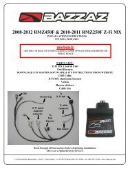
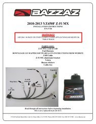
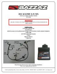
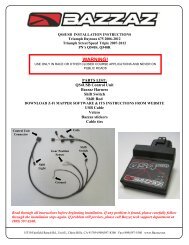
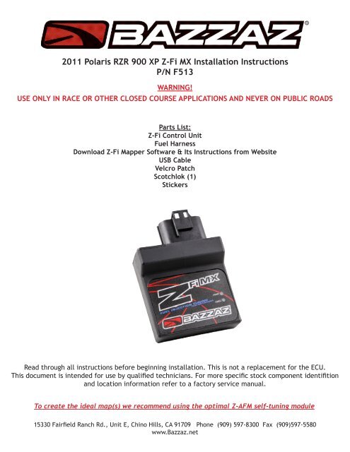
<strong>2011</strong> <strong>Polaris</strong> <strong>RZR</strong> <strong>900</strong> <strong>XP</strong> Z-<strong>Fi</strong> <strong>MX</strong> <strong>Installation</strong> <strong>Instructions</strong>P/N F513WARNING!USE ONLY IN RACE OR OTHER CLOSED COURSE APPLICATIONS AND NEVER ON PUBLIC ROADSParts List:Z-<strong>Fi</strong> Control UnitFuel HarnessDownload Z-<strong>Fi</strong> Mapper Software & Its <strong>Instructions</strong> from WebsiteUSB CableVelcro PatchScotchlok (1)StickersRead through all instructions before beginning installation. This is not a replacement for the ECU.This document is intended for use by qualified technicians. For more specific stock component identifitionand location information refer to a factory service manual.To create the ideal map(s) we recommend using the optimal Z-AFM self-tuning module15330 Fairfield Ranch Rd., Unit E, Chino Hills, CA 91709 Phone (909) 597-8300 Fax (909)597-5580www.<strong>Bazzaz</strong>.net
BAZZAZ HARNESS CONNECTOR IDENTIFICATIONCYL 1 Injectors (gray)CYL 2 Injectors (black)Map selectMainGroundZ-AFM (white)Power & GroundTPSCrank1. Remove the driver & passenger seats, the engine cover panel behind the seats, and in the rear payloadarea in order to gain access to all necessary components (photos 1 & 2).Photo 1 Photo 22. Use the supplied Velcro patch to attach the Z-<strong>Fi</strong><strong>MX</strong> control unit inside the storage compartment locatedunder the driver seat. Connect the mating connector of the <strong>Bazzaz</strong> harness to the Z-<strong>Fi</strong><strong>MX</strong> control unitand begin routing the remainder of the harness into the engine compartment (photo 3).
Photo 33. Route the lead of the <strong>Bazzaz</strong> harness identified as “Crank Position” along the lower frame rail that containsthe seat locking pins to the right side of the vehicle. Locate the connectors of the factory harnessand the crank position sensor which can be found near the bottom of the right side vertical frame raillocated behind the passenger seat. Connect the mating <strong>Bazzaz</strong> connectors in line (photos 4 & 5).Factory CKPSconnectorPhoto 4 Photo 5<strong>Bazzaz</strong> installed4. Continue to route the remainder of the <strong>Bazzaz</strong> harness up the inside of the left vertical frame post(located behind the driver seat), following the routing path of the factory harness. The next two harnessconnections can be easily made by accessing the factory harness connectors from under the vehicle insidethe left rear wheel well (photo 6).
Photo 65. Route the lead of the <strong>Bazzaz</strong> harness identified as “Power” toward the rear of the vehicle and connectthe <strong>Bazzaz</strong> power connector in line with the mating tail light connectors on the factory harness. Thefactory harness connectors can be found attached to the cross brace of the frame just above the air filterhousing (photos 7 & 8).Factory taillight connectorFactoryinjectorconnectors<strong>Bazzaz</strong> powerconnectorsFactory tail lightconnectorsPhoto 7Photo 86. Identify the injector connectors of the factory harness, which are located approximately 12 inchescloser to the engine than the taillight connector along the same lead of the factory harness. Each cylinderhas a set of corresponding injector connectors. The <strong>Bazzaz</strong> harness contains mating connectors for eachcylinder (connectors are color matching to factory harness connectors); connect the corresponding <strong>Bazzaz</strong>connectors in line with the factory harness connectors for each cylinder (photos 9 & 10).
Factory injector connectorsPhoto 9 Photo 10<strong>Bazzaz</strong> connectorsinstalled inline7. Route the remainder of the <strong>Bazzaz</strong> harness containing the throttle position sensor connector throughthe engine compartment, under the intake to the left side of the throttle bodies. This area is best accessedthrough the removal of the engine access cover located in the rear payload compartment.8. Disconnect the factory harness throttle position sensor connector from the throttle body assembly.Crimp on the scotch lok connector supplied with the <strong>Bazzaz</strong> kit onto the green wire. Insert the T-tap connectorattached to the blue wire on the <strong>Bazzaz</strong> harness into the scotch lok. Reinstall the factory harnessconnector onto the throttle position sensor (photos 11, 12 & 13).Factory TPS connectorPhoto 11 Photo 12
Photo 139. Reinstall the components removed in step one of these instructions.The <strong>Bazzaz</strong> controller is capable of storing two maps. These maps can be selected through the use of amap select switch which can be mounted on the handlebar for easy access and can be purchased seperately.Or these maps can be selected by connecting or disconnecting the map select jumper supplied withthe kit. When the map selet jumper is connected the control unit is operating using map 1. When themap select jumper is disconnected the contol unit is operating using map 2.Map 1 Map 2