
You also want an ePaper? Increase the reach of your titles
YUMPU automatically turns print PDFs into web optimized ePapers that Google loves.
www.DanaherMotion.com • 704-588-5693<br />
30<br />
STEP MOTORS<br />
Technical Notes (Continued)<br />
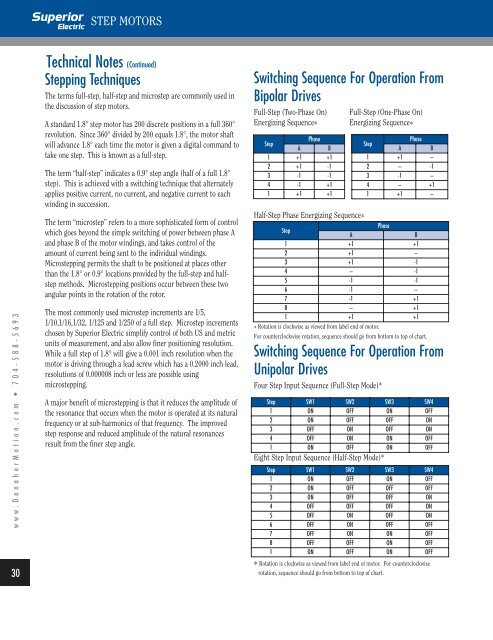
Stepping Techniques<br />
The terms full-<strong>step</strong>, half-<strong>step</strong> and micro<strong>step</strong> are commonly used in<br />
the discussion of <strong>step</strong> <strong>motors</strong>.<br />
A standard 1.8° <strong>step</strong> motor has 200 discrete positions in a full 360°<br />
revolution. Since 360° divided by 200 equals 1.8°, the motor shaft<br />
will advance 1.8° each time the motor is given a digital command to<br />
take one <strong>step</strong>. This is known as a full-<strong>step</strong>.<br />
The term “half-<strong>step</strong>” indicates a 0.9° <strong>step</strong> angle (half of a full 1.8°<br />
<strong>step</strong>). This is achieved with a switching technique that alternately<br />
applies positive current, no current, and negative current to each<br />
winding in succession.<br />
The term “micro<strong>step</strong>” refers to a more sophisticated form of control<br />
which goes beyond the simple switching of power between phase A<br />
and phase B of the motor windings, and takes control of the<br />
amount of current being sent to the individual windings.<br />
Micro<strong>step</strong>ping permits the shaft to be positioned at places other<br />
than the 1.8° or 0.9° locations provided by the full-<strong>step</strong> and half<strong>step</strong><br />
methods. Micro<strong>step</strong>ping positions occur between these two<br />
angular points in the rotation of the rotor.<br />
The most commonly used micro<strong>step</strong> increments are 1/5,<br />
1/10,1/16,1/32, 1/125 and 1/250 of a full <strong>step</strong>. Micro<strong>step</strong> increments<br />
chosen by <strong>Superior</strong> <strong>Electric</strong> simplify control of both US and metric<br />
units of measurement, and also allow finer positioning resolution.<br />
While a full <strong>step</strong> of 1.8° will give a 0.001 inch resolution when the<br />
motor is driving through a lead screw which has a 0.2000 inch lead,<br />
resolutions of 0.000008 inch or less are possible using<br />
micro<strong>step</strong>ping.<br />
A major benefit of micro<strong>step</strong>ping is that it reduces the amplitude of<br />
the resonance that occurs when the motor is operated at its natural<br />
frequency or at sub-harmonics of that frequency. The improved<br />
<strong>step</strong> response and reduced amplitude of the natural resonances<br />
result from the finer <strong>step</strong> angle.<br />
Switching Sequence For Operation From<br />
Bipolar Drives<br />
Full-Step (Two-Phase On) Full-Step (One-Phase On)<br />
Energizing Sequence * Energizing Sequence *<br />
Step<br />
A<br />
Phase<br />
B<br />
1 +1 +1<br />
2 +1 -1<br />
3 -1 -1<br />
4 -1 +1<br />
1 +1 +1<br />
Half-Step Phase Energizing Sequence *<br />
Step<br />
A<br />
Phase<br />
B<br />
1 +1 +1<br />
2 +1 –<br />
3 +1 -1<br />
4 – -1<br />
5 -1 -1<br />
6 -1 –<br />
7 -1 +1<br />
8 – +1<br />
1 +1 +1<br />
* Rotation is clockwise as viewed from label end of motor.<br />
For counterclockwise rotation, sequence should go from bottom to top of chart.<br />
Switching Sequence For Operation From<br />
Unipolar Drives<br />
Four Step Input Sequence (Full-Step Mode)*<br />
Eight Step Input Sequence (Half-Step Mode)*<br />
Step<br />
A<br />
Phase<br />
B<br />
1 +1 –<br />
2 – -1<br />
3 -1 –<br />
4 – +1<br />
1 +1 –<br />
Step SW1 SW2 SW3 SW4<br />
1 ON OFF ON OFF<br />
2 ON OFF OFF ON<br />
3 OFF ON OFF ON<br />
4 OFF ON ON OFF<br />
1 ON OFF ON OFF<br />
Step SW1 SW2 SW3 SW4<br />
1 ON OFF ON OFF<br />
2 ON OFF OFF OFF<br />
3 ON OFF OFF ON<br />
4 OFF OFF OFF ON<br />
5 OFF ON OFF ON<br />
6 OFF ON OFF OFF<br />
7 OFF ON ON OFF<br />
8 OFF OFF ON OFF<br />
1 ON OFF ON OFF<br />
* Rotation is clockwise as viewed from label end of motor. For counterclockwise<br />
rotation, sequence should go from bottom to top of chart.