Sauer-Danfoss series S90 axial piston pumps
Sauer-Danfoss series S90 axial piston pumps
Sauer-Danfoss series S90 axial piston pumps
- TAGS
- series
- axial
- piston
- pumps
- www.bibus.hu

You also want an ePaper? Increase the reach of your titles
YUMPU automatically turns print PDFs into web optimized ePapers that Google loves.
Series 90 Axial<br />
Piston Pumps<br />
Technical<br />
Information
HistoRy of Revisions<br />
Series 90 Axial Piston Pumps<br />
Technical Information<br />
Revisions<br />
© 2008 <strong>Sauer</strong>-<strong>Danfoss</strong>. All rights reserved.<br />
2 520L0603 • Rev FC • August 2008<br />
Table of Revisions<br />
Date Page Changed Rev.<br />
August 2008 8 130 frame size case drain port changed to 1 5/16-12 FC<br />
July 2007 Various Minor edits and dimension changes FB<br />
March 2004 - Revision F F<br />
<strong>Sauer</strong>-<strong>Danfoss</strong> accepts no responsibility for possible errors in catalogs, brochures and other printed material.<br />
<strong>Sauer</strong>-<strong>Danfoss</strong> reserves the right to alter its products without prior notice. This also applies to products<br />
already ordered provided that such alterations aren’t in conflict with agreed specifications. All trademarks in<br />
this material are properties of their respective owners. <strong>Sauer</strong>-<strong>Danfoss</strong> and the <strong>Sauer</strong>-<strong>Danfoss</strong> logotype are<br />
trademarks of the <strong>Sauer</strong>-<strong>Danfoss</strong> Group.
GeneRaL DesCRiPtion<br />
teCHniCaL<br />
sPeCifiCations<br />
oPeRatinG<br />
PaRameteRs<br />
system DesiGn<br />
PaRameteRs<br />
featuRes anD oPtions<br />
Series 90 Axial Piston Pumps<br />
Technical Information<br />
Contents<br />
Series 90 family of <strong>pumps</strong> and motors ................................................................................................... 5<br />
Plus+1 Compliant controls and sensors ................................................................................................. 5<br />
Design ................................................................................................................................................................ 6<br />
Pictorial circuit diagram ............................................................................................................................... 7<br />
System schematic ........................................................................................................................................... 7<br />
Features and options .................................................................................................................................... 8<br />
Operating parameters .................................................................................................................................. 8<br />
Fluid specifications ........................................................................................................................................ 9<br />
Overview .........................................................................................................................................................10<br />
Input speed ....................................................................................................................................................10<br />
System pressure ............................................................................................................................................10<br />
Case Pressure .................................................................................................................................................10<br />
Hydraulic Fluids .............................................................................................................................................11<br />
Temperature and viscosity ........................................................................................................................11<br />
Fluid and filtration ........................................................................................................................................12<br />
Charge pressure ............................................................................................................................................12<br />
Independent braking system ...................................................................................................................12<br />
Reservoir ..........................................................................................................................................................12<br />
Case drain ........................................................................................................................................................13<br />
Sizing equations ...........................................................................................................................................13<br />
Shaft Loads .....................................................................................................................................................14<br />
Shaft Availability and Torque Ratings ...................................................................................................15<br />
Filtration options ..........................................................................................................................................16<br />
Displacement limiter ...................................................................................................................................16<br />
Suction filtration – option S ................................................................................................................16<br />
Charge pressure filtration – option R, T, P, and L ...........................................................................16<br />
Overpressure protection ......................................................................................................................17<br />
Pressure limiting function....................................................................................................................17<br />
Multi-function valves ..................................................................................................................................17<br />
Bypass Function ......................................................................................................................................18<br />
Speed sensor ..................................................................................................................................................19<br />
Charge Pump .................................................................................................................................................19<br />
Charge pump sizing/selection ...........................................................................................................20<br />
Charge pump flow and power curves .............................................................................................20<br />
Auxiliary Mounting Pads ............................................................................................................................21<br />
Mating pump requirements ...............................................................................................................21<br />
Mounting Flange Loads .............................................................................................................................22<br />
Estimating overhung load moments ...............................................................................................22<br />
520L0603 • Rev FC • August 2008<br />
3
ContRoL oPtions<br />
instaLLation<br />
DRawinGs<br />
Series 90 Axial Piston Pumps<br />
Technical Information<br />
Contents<br />
4 520L0603 • Rev FC • August 2008<br />
3 -Position (FNR) Electric Control ............................................................................................................23<br />
Response time .........................................................................................................................................23<br />
Electric Displacement Control (EDC) .....................................................................................................24<br />
Operation ...................................................................................................................................................24<br />
Features and Benefits ............................................................................................................................24<br />
(continued) ................................................................................................................................................25<br />
Control signal requirements ...............................................................................................................25<br />
Response time .........................................................................................................................................25<br />
Pump output flow direction vs. control current ..........................................................................25<br />
Hydraulic Displacement Control (HDC) ................................................................................................26<br />
Operation ...................................................................................................................................................26<br />
Features and benefits of the hydraulic displacement control: ...............................................26<br />
Control signal requirements ...............................................................................................................27<br />
Response time .........................................................................................................................................27<br />
Manual Displacement Control (MDC) ...................................................................................................28<br />
Operation ...................................................................................................................................................28<br />
Features and benefits of the manual displacement control: ...................................................28<br />
External control handle requirements ............................................................................................29<br />
Response time .........................................................................................................................................29<br />
Non-linear Manual Displacement Control (MDC) .............................................................................30<br />
Features and benefits of the non-linear manual displacement control: .............................30<br />
External control handle requirements ............................................................................................31<br />
Response time .........................................................................................................................................31<br />
Non feedback proportional electric control (NFPE) ........................................................................32<br />
Features and benefits of the NFPE control when used with sauer-danfoss<br />
microcontroller ........................................................................................................................................33<br />
Input signal requirements ...................................................................................................................33<br />
Frame size 042 ...............................................................................................................................................34<br />
Frame size 055 ...............................................................................................................................................36<br />
Frame size 075 ...............................................................................................................................................40<br />
Frame size 100 ...............................................................................................................................................44<br />
Frame size 130 ...............................................................................................................................................48<br />
Frame size 180 ...............................................................................................................................................51<br />
Frame size 250 ...............................................................................................................................................55<br />
Cover plate ......................................................................................................................................................59<br />
3-position (F-N-R) electric control ..........................................................................................................59<br />
Electric Displacement Control (EDC) with MS-Connector or Packard® connector ...............60<br />
Hydraulic Displacement Control (HDC) ................................................................................................60<br />
Manual Displacement Control (MDC) with neutral start switch .................................................61<br />
Non-linear Manual Displacement Control (MDC) .............................................................................61<br />
Electrohydraulic Displacement Control (NFPE) .................................................................................62<br />
(except 075 NFPE) ........................................................................................................................................62<br />
Integral Pressure Filter ................................................................................................................................63<br />
Remote pressure – without filter ............................................................................................................63<br />
Frame size 075 NFPE....................................................................................................................................64
seRies 90 famiLy of<br />
PumPs anD motoRs<br />
PLus+1 ComPLiant<br />
ContRoLs anD<br />
sensoRs<br />
Series 90 Axial Piston Pumps<br />
Technical Information<br />
General description<br />
Series 90 hydrostatic <strong>pumps</strong> and motors can be applied together or combined with<br />
other products in a system to transfer and control hydraulic power. They are intended for<br />
closed circuit applications.<br />
<strong>series</strong> 90 variable displacement <strong>pumps</strong> are compact, high power density units. All<br />
models utilize the parallel <strong>axial</strong> <strong>piston</strong>/slipper concept in conjunction with a tiltable<br />
swashplate to vary the pump’s displacement. Reversing the angle of the swashplate<br />
reverses the flow of oil from the pump and thus reverses the direction of rotation of the<br />
motor output.<br />
Series 90 <strong>pumps</strong> include an integral charge pump to provide system replenishing<br />
and cooling oil flow, as well as control fluid flow. They also feature a range of auxiliary<br />
mounting pads to accept auxiliary hydraulic <strong>pumps</strong> for use in complementary hydraulic<br />
systems. A complete family of control options is available to suit a variety of control<br />
systems (mechanical, hydraulic, electric).<br />
<strong>series</strong> 90 motors also use the parallel <strong>axial</strong> <strong>piston</strong>/slipper design in conjunction with a<br />
fixed or tiltable swashplate. They can intake/discharge fluid through either port; they are<br />
bidirectional. They also include an optional loop flushing feature that provides additional<br />
cooling and cleaning of fluid in the working loop.<br />
• Series 90 – advanced technology today<br />
• Seven sizes of variable displacement <strong>pumps</strong><br />
• Five sizes of fixed displacement motors<br />
• One variable displacement motor<br />
• SAE and cartridge mount configurations<br />
• Efficient <strong>axial</strong> <strong>piston</strong> design<br />
• Proven reliability and performance<br />
• Compact, lightweight<br />
• Worldwide sales and service<br />
• Plus+1 compliant controls and sensors<br />
Series 90 controls and sensors are PLUS+1 compliant. PLUS+1 compliance means<br />
our controls and sensors are directly compatible with the PLUS+1 machine control<br />
architecture. Adding Series 90 <strong>pumps</strong> to your application using PLUS+1 GUIDE software<br />
is as easy as drag-and-drop. Software development that used to take months can now<br />
be done in just a few hours. For more information on PLUS+1 GUIDE, visit www.sauerdanfoss.com/plus1.<br />
520L0603 • Rev FC • August 2008<br />
5
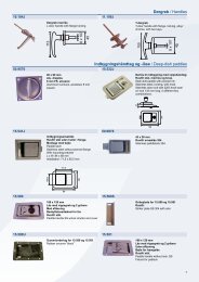
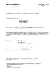
Slider block<br />
Series 90 Axial Piston Pumps<br />
Technical Information<br />
General description<br />
DesiGn Series 90 pump cross-section<br />
Bushing<br />
Cylinder block<br />
Valve plate<br />
Rear<br />
bushing<br />
Charge pump<br />
Name plate<br />
Model<br />
Code<br />
Servo <strong>piston</strong><br />
6 520L0603 • Rev FC • August 2008<br />
Model-No./Ident-No.<br />
Model Code<br />
Serial-No.<br />
Servo arm<br />
Swashplate<br />
Piston<br />
90L055 KA 1 N<br />
6 S 3 C6 C 03<br />
NNN 35 35 24<br />
Made in USA<br />
501829<br />
N - 88 - 126 - 67890<br />
P104 291E<br />
Slipper<br />
Cradle guide<br />
Model<br />
Number<br />
Serial<br />
Number<br />
Displacement control<br />
Place of Manufacture<br />
Feedback linkage<br />
Cradle bearing<br />
Roller bearing<br />
Shaft<br />
seal<br />
Input shaft<br />
P106 648E
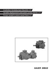
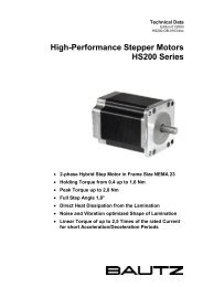
PiCtoRiaL CiRCuit<br />
DiaGRam<br />
Control handle<br />
Reversible variable<br />
displacement pump<br />
Input shaft<br />
Pump swashplate<br />
Working loop (high pressure)<br />
system sCHematiC<br />
M<br />
M1<br />
M4<br />
M5<br />
M2<br />
Series 90 Axial Piston Pumps<br />
Technical Information<br />
General description<br />
Displacement control valve<br />
Servo control cylinder<br />
Servo control cylinder<br />
Pump Motor<br />
S<br />
This configuration shows a hydrostatic transmission using a Series 90 <strong>axial</strong> <strong>piston</strong><br />
variable displacement pump and a Series 90 fixed displacement motor.<br />
Orificed check<br />
valve<br />
Working loop (low pressure) Suction line Control fluid Case drain fluid<br />
M3<br />
520L0603 • Rev FC • August 2008<br />
Heat exchanger bypass valve<br />
Heat exchanger<br />
Charge pressure relief valve<br />
Multi-function valve<br />
Servo<br />
pressure<br />
relief valves<br />
L2<br />
To<br />
pump<br />
case<br />
Charge pump<br />
Multi-function valve<br />
B<br />
Reservoir<br />
A A<br />
B<br />
Vacuum gauge<br />
Loop flushing valve<br />
Purge relief valve<br />
Fixed displacement motor<br />
Motor swashplate<br />
L2 M3 M1<br />
L1<br />
M2<br />
P102 000<br />
Output shaft<br />
P104 286E<br />
7
featuRes anD oPtions<br />
feature unit<br />
Displacement cm³/rev<br />
Flow at rated speed<br />
(theoretical)<br />
Torque at maximum<br />
displacement (theoretical)<br />
Mass moment of inertia of<br />
Series 90 Axial Piston Pumps<br />
Technical Information<br />
Technical specifications<br />
[in³]/rev<br />
l/min<br />
[US gal/min]<br />
N•m/bar<br />
[lbf•in/1000 psi]<br />
kg•m²<br />
8 520L0603 • Rev FC • August 2008<br />
042 055 075<br />
frame<br />
100 130 180 250<br />
42<br />
55<br />
75<br />
100<br />
130<br />
180<br />
250<br />
[2.56]<br />
176<br />
[46]<br />
0.67<br />
[410]<br />
0.0023<br />
[3.35]<br />
215<br />
[57]<br />
0.88<br />
[530]<br />
0.0060<br />
[4.59]<br />
270<br />
[71]<br />
1.19<br />
[730]<br />
0.0096<br />
[6.10]<br />
330<br />
[87]<br />
1.59<br />
[970]<br />
0.0150<br />
[7.93]<br />
403<br />
[106]<br />
2.07<br />
[1260]<br />
0.0023<br />
[10.98]<br />
468<br />
[124]<br />
2.87<br />
[1750]<br />
0.0380<br />
[15.25]<br />
575<br />
[160]<br />
3.97<br />
[2433]<br />
0.0650<br />
rotating components<br />
[slug•ft²] [0.0017] [0.0044] [0.0071] [0.0111] [0.0170] [0.0280] [0.0479]<br />
Weight (with control opt. MA) kg [lb] 34 [75] 40 [88] 49 [108] 68 [150] 88 [195] 136 [300] 154 [340]<br />
Mounting (per SAE J744) B C C C D E E<br />
Rotation Clockwise or Counterclockwise<br />
Main ports: 4-bolt split-flange mm<br />
19.05 25.4<br />
25.4<br />
25.4 31.75 31.75 38.1<br />
(per SAE J518 code 62)<br />
[in]<br />
[0.75] [1.0] [1.0] [1.0] [1.25] [1.25] [1.5]<br />
Main port configuration Radial Radial or <strong>axial</strong> Radial<br />
Case drain ports (SAE O-ring boss) UNF thread (in.) 0.875–14 1.0625–12 1.0625–12 1.0625–12 1.3125–12 1.625–12 1.625–12<br />
Other ports SAE O-ring boss. See Installation drawings, page 34.<br />
Shafts Splined, straight keyed, and tapered shafts available. See Shafts, page 15.<br />
Auxiliary mounting SAE-A, B, C SAE-A, B, C, D SAE-A, B, C, D, E<br />
Installation position Installation is recommended with control on the top or side. Consult your <strong>Sauer</strong>-<strong>Danfoss</strong><br />
oPeRatinG PaRameteRs<br />
representative for nonconformance guidelines. The housing must remain filled with hydraulic fluid.<br />
Parameter<br />
input speed<br />
unit<br />
042 055 075<br />
frame<br />
100 130 180 250<br />
Minimum<br />
min-1 500 500 500 500 500 500 500<br />
Continuous (rpm) 4200 3900 3600 3300 3100 2600 2300<br />
Maximum 4600 4250 3950 3650 3400 2850 2500<br />
system pressure<br />
Rated<br />
420 [6000]<br />
Maximum bar [psi]<br />
450 [6500]<br />
Minimum low loop<br />
inlet pressure (charge inlet)<br />
10 [150]<br />
Minimum (continuous) bar (abs.)<br />
0.7 [9]<br />
Minimum (cold start)<br />
Case pressure<br />
[in. Hg vac.]<br />
0.2 [24]<br />
Continuous<br />
Maximum (cold start)<br />
bar [psi]<br />
3 [40]<br />
5 [75]
fLuiD sPeCifiCations<br />
Series 90 Axial Piston Pumps<br />
Technical Information<br />
Technical specifications<br />
viscosity mm²/sec (cSt) [SUS]<br />
temperature °C [°F]<br />
filtration<br />
520L0603 • Rev FC • August 2008<br />
Minimum 7 [49]<br />
Continuous 12-80 [70-370]<br />
Maximum 1600 [7500]<br />
Minimum -40 [-40]<br />
Continuous 104 [220]<br />
Maximum 115 [240]<br />
Cleanliness 18/13 or better per ISO 4406<br />
Efficiency (suction filtration) β 35-45=75 (β 10≥2)<br />
Efficiency (charge filtration) β 15-20=75 (β 10≥10)<br />
Recommended inlet screen size 100-125 µm [0.0039-0.0049 in]<br />
9
oveRview<br />
inPut sPeeD<br />
system PRessuRe<br />
Case PRessuRe<br />
Series 90 Axial Piston Pumps<br />
Technical Information<br />
Operating parameters<br />
10 520L0603 • Rev FC • August 2008<br />
Maintain operating parameters within prescribed limits during all operating conditions.<br />
This section defines operating limits given in the table Operating parameters, page 8.<br />
minimum speed is the lowest input speed recommended during engine idle condition.<br />
Operating below minimum speed limits the pump’s ability to maintain adequate flow for<br />
lubrication and power transmission.<br />
Continuous speed is the highest input speed recommended at full power condition.<br />
Operating at or below this speed should yield satisfactory product life.<br />
maximum speed is the highest operating speed permitted. Exceeding maximum speed<br />
reduces product life and can cause loss of hydrostatic power and braking capacity. Never<br />
exceed the maximum speed limit under any operating conditions.<br />
Consult Pressure and speed limits, BLN-9984, when determining speed limits for a<br />
particular application.<br />
W Warning<br />
unintended vehicle or machine movement hazard.<br />
Exceeding maximum speed may cause a loss of hydrostatic drive line power and<br />
braking capacity. You must provide a braking system, redundant to the hydrostatic<br />
transmission, sufficient to stop and hold the vehicle or machine in the event of<br />
hydrostatic drive power loss.<br />
system pressure is the differential pressure between system ports A and B. It is the<br />
dominant operating variable affecting hydraulic unit life. High system pressure, which<br />
results from high load, reduces expected life. System pressure must remain at or below<br />
continuous pressure during normal operation to achieve expected life.<br />
Continuous pressure is the average, regularly occurring operating pressure. Operating<br />
at or below this pressure should yield satisfactory product life.<br />
maximum pressure is the highest intermittent pressure allowed. Maximum machine<br />
load should never exceed this pressure. For all applications, the load should move below<br />
this pressure.<br />
All pressure limits are differential pressures referenced to low loop (charge) pressure.<br />
Subtract low loop pressure from gauge readings to compute the differential.<br />
Under normal operating conditions, the maximum continuous case pressure must not<br />
exceed 3 bar (44 psi). Maximum allowable intermittent case pressure during cold start<br />
must not exceed 5 bar (73 psi). Size drain plumbing accordingly.<br />
C Caution<br />
Possible component damage or leakage<br />
Operation with case pressure in excess of these limits may damage seals, gaskets, and/or<br />
housings, causing external leakage. Performance may also be affected since charge and<br />
system pressure are additive to case pressure.
HyDRauLiC fLuiDs<br />
temPeRatuRe anD<br />
visCosity<br />
Series 90 Axial Piston Pumps<br />
Technical Information<br />
Operating parameters<br />
Ratings and data are based on operating with hydraulic fluids containing oxidation, rust<br />
and foam inhibitors. These fluids must possess good thermal and hydrolytic stability to<br />
prevent wear, erosion, and corrosion of pump components. Never mix hydraulic fluids of<br />
different types.<br />
Fire resistant fluids are also suitable at modified operating conditions. Please see <strong>Sauer</strong>-<br />
<strong>Danfoss</strong> publication 520L0463 for more information. Refer to publication 520L0465 for<br />
information relating to biodegradable fluids.<br />
Suitable Hydraulic fluids:<br />
• Hydraulic fluids per DIN 51 524, 2-HLP,<br />
• Hydraulic fluids per DIN 51 524, 3-HVLP,<br />
• API CD, CE and CF engine fluids per SAE J183,<br />
• M2C33F or G automatic transmission fluids (ATF),<br />
• Dexron II (ATF), which meets the Allison C3- and Caterpillar TO-2 test,<br />
• Agricultural multi purpose oil (STOU),<br />
• Premium turbine oils.<br />
Temperature and viscosity requirements must be concurrently satisfied. The data shown<br />
in the table Fluid specifications, page 9, assume petroleum-based fluids are used.<br />
The high temperature limits apply at the hottest point in the transmission, which is<br />
normally the motor case drain. The system should generally be run at or below the rated<br />
temperature. The maximum temperature is based on material properties and should<br />
never be exceeded.<br />
Cold oil will generally not affect the durability of the transmission components, but<br />
it may affect the ability of oil to flow and transmit power; therefore temperatures<br />
should remain 16 °C [30 °F] above the pour point of the hydraulic fluid. The minimum<br />
temperature relates to the physical properties of component materials.<br />
For maximum unit efficiency and bearing life the fluid viscosity should remain in the<br />
recommended operating range. The minimum viscosity should be encountered<br />
only during brief occasions of maximum ambient temperature and severe duty cycle<br />
operation. The maximum viscosity should be encountered only at cold start.<br />
Heat exchangers should be sized to keep the fluid within these limits. Testing to verify<br />
that these temperature limits are not exceeded is recommended.<br />
520L0603 • Rev FC • August 2008<br />
11
fLuiD anD fiLtRation<br />
CHaRGe PRessuRe<br />
inDePenDent bRakinG<br />
system<br />
ReseRvoiR<br />
Series 90 Axial Piston Pumps<br />
Technical Information<br />
System design parameters<br />
12 520L0603 • Rev FC • August 2008<br />
To prevent premature wear, it is imperative that only clean fluid enter the hydrostatic<br />
transmission circuit. A filter capable of controlling the fluid cleanliness to ISO 4406 class<br />
22/18/13 (SAE J1165) or better under normal operating conditions is recommended.<br />
The filter may be located either on the inlet (suction filtration) or discharge (charge<br />
pressure filtration) side of the charge pump. The selection of a filter depends on<br />
a number of factors including the contaminant ingression rate, the generation of<br />
contaminants in the system, the required fluid cleanliness, and the desired maintenance<br />
interval. Filters are selected to meet the above requirements using rating parameters of<br />
efficiency and capacity.<br />
Filter efficiency may be measured with a Beta ratio ¹ (β X). For simple suction-filtered closed<br />
circuit transmissions and open circuit transmissions with return line filtration,<br />
a filter with a β-ratio within the range of β 35-45 = 75 (β 10 ≥ 2) or better has been found to<br />
be satisfactory. For some open circuit systems, and closed circuits with cylinders being<br />
supplied from the same reservoir, a considerably higher filter efficiency is recommended.<br />
This also applies to systems with gears or clutches using a common reservoir. For these<br />
systems, a charge pressure or return filtration system with a filter β-ratio in the range of<br />
β 15-20 = 75 (β 10 ≥ 10) or better is typically required.<br />
Because each system is unique, only a thorough testing and evaluation program can fully<br />
validate the filtration system. Please see Design Guidelines for Hydraulic Fluid Cleanliness,<br />
520L0467, for more information.<br />
The charge pressure setting listed in the model code is based on the charge flow across<br />
the charge pressure relief valve at fluid temperature of 50 °C [120 °F].<br />
W Warning<br />
unintended vehicle or machine movement hazard.<br />
The loss of hydrostatic drive line power, in any mode of operation (forward, neutral, or<br />
reverse) may cause the system to lose hydrostatic braking capacity. You must provide a<br />
braking system, redundant to the hydrostatic transmission, sufficient to stop and hold<br />
the vehicle or machine in the event of hydrostatic drive power loss.<br />
The reservoir should be designed to accommodate maximum volume changes during<br />
all system operating modes and to promote de-aeration of the fluid as it passes through<br />
the tank.<br />
A suggested minimum total reservoir volume is 5/8 of the maximum charge pump<br />
flow per minute with a minimum fluid volume equal to 1/2 of the maximum charge<br />
pump flow per minute. This allows 30 seconds fluid dwell for removing entrained air at<br />
the maximum return flow. This is usually adequate to allow for a closed reservoir (no<br />
breather) in most applications.<br />
1 Filter βx-ratio is a measure of filter efficiency defined by ISO 4572. It is defined as the ratio of the number of<br />
particles greater than a given diameter (“x” in microns) upstream of the filter to the number of these particles<br />
downstream of the filter.
ReseRvoiR<br />
(continued)<br />
Case DRain<br />
sizinG equations<br />
Series 90 Axial Piston Pumps<br />
Technical Information<br />
System design parameters<br />
Locate the reservoir outlet (charge pump inlet) above the bottom of the reservoir to take<br />
advantage of gravity separation and prevent large foreign particles from entering the charge<br />
inlet line. A 125 μm screen over the outlet port is recommended. Position the reservoir inlet<br />
(fluid return) to discharge below the normal fluid level, toward the interior of the tank. A<br />
baffle (or baffles) will further promote de-aeration and reduce surging of the fluid.<br />
A case drain line must be connected to one of the case outlets (L1 or L2) to return<br />
internal leakage to the system reservoir. The higher of the two case outlets should be<br />
used to promote complete filling of the case. Since case drain fluid is typically the hottest<br />
fluid in the system, it is advantageous to return this flow through the heat exchanger.<br />
The following equations are helpful when sizing hydraulic <strong>pumps</strong>. Generally, the sizing<br />
process is initiated by an evaluation of the machine system to determine the required<br />
motor speed and torque to perform the necessary work function. Refer to Selection of<br />
drive line components, bLn-9885, for a more complete description of hydrostatic drive<br />
line sizing. First, the motor is sized to transmit the maximum required torque. The pump<br />
is then selected as a flow source to achieve the maximum motor speed.<br />
SI units Output flow Q = (l/min) Vg = Displacement per revolution<br />
(cm<br />
Input torque M = (N•m)<br />
Input power P = = (kW)<br />
3 /rev)<br />
∆p =<br />
n =<br />
pO - pi (system pressure)<br />
(bar)<br />
Speed (min-1 Vg • n • ηv 1000<br />
Vg • ∆p<br />
20 • π • ηm (rpm))<br />
M • n • π<br />
30 000<br />
Q • ∆p<br />
600 • ηt ηv =<br />
ηm =<br />
ηt =<br />
Volumetric efficiency<br />
Mechanical efficiency<br />
Overall efficiency (ηv • ηm) US units Vg = Displacement per revolution<br />
(in3 /rev)<br />
∆p =<br />
n =<br />
pO - pi (system pressure)<br />
(psi)<br />
Speed (min-1 Output flow Q =<br />
Vg • n • ηv 231<br />
(US gal/min)<br />
Input torque M =<br />
Vg • ∆p<br />
2 • π • ηm (lbf•in)<br />
(rpm))<br />
M • n • π<br />
Input power P =<br />
198 000<br />
Q • ∆p<br />
=<br />
1714 • ηt (hp)<br />
ηv =<br />
ηm =<br />
ηt =<br />
Volumetric efficiency<br />
Mechanical efficiency<br />
Overall efficiency (ηv • ηm) 520L0603 • Rev FC • August 2008<br />
13
Series 90 Axial Piston Pumps<br />
Technical Information<br />
System design parameters<br />
sHaft LoaDs Normal bearing life in B 10 hours is shown in the table below. The figures reflect a<br />
continuous differential pressure of 240 bar [3500 psi], 1800 min -1 (rpm) shaft speed,<br />
maximum displacement, and no external shaft side load. The data is based on a 50%<br />
forward, 50% reverse duty cycle, standard charge pump size, and standard charge<br />
pressure.<br />
Series 90 <strong>pumps</strong> are designed with<br />
bearings that can accept external radial<br />
and thrust loads. The external radial<br />
shaft load limits are a function of the<br />
load position and orientation, and the<br />
operating conditions of the unit.<br />
The maximum allowable radial load<br />
(Re), is based on the maximum external<br />
moment (Me), and the distance (L) from<br />
the mounting flange to the load. It may<br />
be determined using the table and<br />
formula below. Thrust (<strong>axial</strong>) load limits<br />
are also shown.<br />
14 520L0603 • Rev FC • August 2008<br />
Bearing life<br />
frame size bearing life – b 10 hrs<br />
42 18 060<br />
55 22 090<br />
75 22 970<br />
100 22 670<br />
130 17 990<br />
180 16 150<br />
250 12 020<br />
Re = me / L<br />
All external shaft loads affect bearing life.<br />
In applications with external shaft loads,<br />
180˚Re<br />
Pump<br />
swashplate<br />
minimize the impact by positioning the load at 90° or 270° as shown in the figure.<br />
Contact your <strong>Sauer</strong>-<strong>Danfoss</strong> representative for an evaluation of unit bearing life if:<br />
• continuously applied external loads exceed 25 % of the maximum allowable radial<br />
load (Re).<br />
• the pump swashplate is positioned on one side of center all or most of the time.<br />
• the unit bearing life (B 10) is critical.<br />
<strong>Sauer</strong>-<strong>Danfoss</strong> recommends tapered input shafts or clamp-type couplings for<br />
applications with radial shaft loads.<br />
Allowable external shaft load<br />
Parameter 042 055 075 100 130 180 250<br />
External moment (Me)<br />
N•m [lbf•in]<br />
Maximum shaft thrust in (T in)<br />
N [lbf ]<br />
Maximum shaft thrust out (T out)<br />
N [lbf ]<br />
126<br />
[1114]<br />
2635<br />
[592]<br />
1020<br />
[229]<br />
101<br />
[893]<br />
3340<br />
[750]<br />
910<br />
[204]<br />
Radial and thrust load position<br />
L<br />
0˚Re<br />
90˚<br />
Re<br />
118<br />
[1043]<br />
4300<br />
[996]<br />
930<br />
[209]<br />
126<br />
[1114]<br />
5160<br />
[1160]<br />
1000<br />
[224]<br />
270˚<br />
Re<br />
Tout Tin<br />
140<br />
[1238]<br />
5270<br />
[1184]<br />
688<br />
[154]<br />
Re<br />
161<br />
[1424]<br />
7000<br />
[1573]<br />
1180<br />
[265]<br />
P104 292E<br />
176<br />
[1556]<br />
7826<br />
[1759]<br />
1693<br />
[380]
sHaft avaiLabiLity<br />
anD toRque RatinGs<br />
Contact your <strong>Sauer</strong>-<strong>Danfoss</strong><br />
representative for tapered<br />
shaft torque ratings.<br />
Legend:<br />
— Not available<br />
+ Not recommended<br />
for front pump in<br />
tandem configurations<br />
* Based on external<br />
moment load on<br />
shaft equal to half the<br />
maximum torque valve<br />
Series 90 Axial Piston Pumps<br />
Technical Information<br />
Features and options<br />
Through torque diagram<br />
M e3<br />
for the next pump<br />
Shaft availability and torque ratings<br />
shaft description<br />
Shaft availability and torque ratings N•m [lbf•in]<br />
and option code<br />
15 teeth<br />
16/32 pitch<br />
spline<br />
19 teeth<br />
16/32 pitch<br />
spline<br />
21 teeth<br />
16/32 pitch<br />
spline<br />
23 teeth<br />
16/32 pitch<br />
spline<br />
27 teeth<br />
16/32 pitch<br />
spline<br />
13 teeth 8/16<br />
pitch spline<br />
14 teeth<br />
12/24 pitch<br />
spline<br />
C3<br />
C5<br />
520L0603 • Rev FC • August 2008<br />
042 055 075 100 130 180 250<br />
530<br />
[4700]<br />
900<br />
[8000]<br />
C6 —<br />
— — — — — —<br />
— — — — — —<br />
1130<br />
[10 000]<br />
C7 — —<br />
— — — — —<br />
1580<br />
[14 000]<br />
1580<br />
[14 000]<br />
C8 — — — —<br />
F1 — — —<br />
S1 —<br />
1.375 Str key K1 —<br />
1.5 Str key K2 —<br />
735<br />
[6500]<br />
768*<br />
[6800]<br />
735<br />
[6500]<br />
1810<br />
[16 000]<br />
— — —<br />
2938<br />
[26 000]<br />
1810<br />
[16 000]<br />
2938<br />
[26 000]<br />
1810 +<br />
[16 000] +<br />
2938<br />
[26 000]<br />
1810 +<br />
[16 000] +<br />
735 +<br />
[6500] + — — —<br />
— — — — —<br />
1130*<br />
[10 000]<br />
1.75 Str key K3 — — —<br />
1.375 tapered T1 —<br />
768*<br />
[6800]<br />
1.5 tapered T2 — —<br />
768*<br />
[6800]<br />
1130*<br />
[10 000]<br />
— — — —<br />
1582*<br />
[14 000]<br />
— — —<br />
— — — —<br />
1130*<br />
[10 000]<br />
1.75 tapered T4 — — — —<br />
1.00 tapered T3<br />
Third<br />
stage<br />
M e2<br />
for the<br />
second pump<br />
497*<br />
[4400]<br />
Second stage<br />
for the first pump<br />
M e1<br />
— — —<br />
1582*<br />
[14 000]<br />
First stage<br />
P102 014E<br />
M e Input torque<br />
torque required by auxiliary <strong>pumps</strong> is additive. ensure requirements don’t exceed shaft torque ratings.<br />
— —<br />
— — — — — —<br />
15
Series 90 Axial Piston Pumps<br />
Technical Information<br />
Features and options<br />
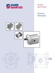
fiLtRation oPtions suction filtration – option s<br />
The suction filter is placed in the circuit<br />
between the reservoir and the inlet to<br />
the charge pump, as shown below.<br />
The use of a filter contamination monitor<br />
is recommended.<br />
16 520L0603 • Rev FC • August 2008<br />
Suction filtration<br />
To low<br />
loop and<br />
control<br />
Hydraulic fluid reservoir<br />
Charge pump<br />
Filter<br />
Adjustable<br />
charge pressure relief valve<br />
To pump case<br />
Charge pressure filtration – option R, t, P, and L<br />
The pressure filter can be mounted<br />
Charge pressure filtration<br />
directly on the pump or mounted<br />
Screen<br />
remotely for ease of servicing. A 100-<br />
125 μm mesh screen, located in the<br />
Hydraulic fluid reservoir<br />
reservoir or the charge inlet line, is<br />
recommended when using charge<br />
Charge pump<br />
pressure filtration. This system requires<br />
a filter capable of withstanding charge<br />
Filter<br />
pressure.<br />
DisPLaCement LimiteR All Series 90 <strong>pumps</strong> are designed with<br />
optional mechanical displacement<br />
(stroke) limiters.<br />
The maximum displacement of the<br />
pump can be set independently for<br />
forward and reverse using the two<br />
adjustment screws.<br />
Displacement limiter location<br />
Displacement<br />
Pump rotation<br />
Right<br />
Left<br />
limiter mounted<br />
on servo side<br />
To low<br />
pressure<br />
side and<br />
control<br />
Displacement<br />
limitation at high<br />
pressure side<br />
1 A<br />
2 B<br />
1 B<br />
2 A<br />
Manometer<br />
P102 003E<br />
Adjustable<br />
charge pressure<br />
relief valve<br />
Displacement limiter<br />
Displacement limiter adjustment screw<br />
Servo <strong>piston</strong><br />
To pump case<br />
P102 004E<br />
Servo<br />
cylinder<br />
P102 005E
Series 90 Axial Piston Pumps<br />
Technical Information<br />
Features and options<br />
muLti-funCtion vaLves overpressure protection<br />
The Series 90 <strong>pumps</strong> are designed with a sequenced pressure limiting system and high<br />
pressure relief valves. When the preset pressure is reached, the pressure limiter system<br />
acts to rapidly destroke the pump to limit the system pressure. For unusually rapid load<br />
application, the high pressure relief valve is also available to limit the pressure level. The<br />
pressure limiter sensing valve acts as the pilot for the relief valve spool, such that the<br />
relief valve is sequenced to operate above the pressure limiter level.<br />
Both the pressure limiter sensing valves and relief valves are built into the multi-function<br />
valves located in the pump endcap. The sequenced pressure limiter/high pressure relief<br />
valve system in the Series 90 provides an advanced design of overpressure protection.<br />
The pressure limiter avoids system overheating associated with relief valves and the<br />
sequenced relief valves are available to limit pressure spikes which exist in severe<br />
operating conditions.<br />
Because the relief valves open only during extremely fast pressure spike conditions,<br />
heat generation is minimized during the short time that they might be open. For some<br />
applications, such as dual path vehicles, the pressure limiter function may be defeated<br />
such that only the relief valve function remains. The relief response is approximately 20<br />
ms whether used with or without the pressure limiter function.<br />
Pressure limiting function<br />
When set pressure is exceeded, the pressure sensing valve (A) flows oil through passage<br />
(B) and across an orifice in the control spool raising pressure on the servo which was<br />
at low pressure. Servo pressure relief valves (C) limit servo pressure to appropriate<br />
levels. The pressure limiter action cancels the input command of the displacement<br />
control and tends to equalize servo pressure. Swashplate moments assist to change the<br />
displacement as required to maintain system pressure at the set point.<br />
520L0603 • Rev FC • August 2008<br />
17
muLti-funCtion vaLves<br />
(continued)<br />
M<br />
M1<br />
M4<br />
M5<br />
M2<br />
S<br />
Series 90 Axial Piston Pumps<br />
Technical Information<br />
Features and options<br />
18 520L0603 • Rev FC • August 2008<br />
Multifunction valve, pressure limiter, pressure regulation, option 1<br />
M3<br />
L2<br />
A<br />
B<br />
Servo <strong>piston</strong><br />
Port A<br />
Port B<br />
Servo <strong>piston</strong><br />
To control<br />
Servo pressure<br />
relief valves<br />
Multifunction valve<br />
Multifunction valve<br />
Charge<br />
pressure<br />
relief valve<br />
bypass function<br />
In some applications it is desirable to bypass fluid around the variable displacement<br />
pump when pump shaft rotation is either not possible or not desired. For example, an<br />
inoperable vehicle may be moved to a service or repair location or winched onto a trailer<br />
without operating the prime mover. To provide for this, Series 90 <strong>pumps</strong> are designed<br />
with a bypass function.<br />
The bypass is operated by mechanically rotating the bypass hex on both multifunction<br />
valves three (3) turns counterclockwise (CCW). This connects working loop A and B and<br />
allows fluid to circulate without rotating the pump and prime mover.<br />
C Caution<br />
Possible pump and/or motor damage<br />
Bypass valves are intended for moving a machine or vehicle for very short distances at<br />
very slow speeds. They are NOT intended as tow valves.<br />
A<br />
B<br />
C<br />
Bypass hex<br />
adjustment<br />
P102 007E
Series 90 Axial Piston Pumps<br />
Technical Information<br />
Features and options<br />
sPeeD sensoR An optional speed sensor for direct<br />
measurement of speed is available. This<br />
sensor may also be used to sense the<br />
direction of rotation.<br />
A special magnetic ring is pressed onto<br />
the outside diameter of the cylinder<br />
block and a Hall effect sensor is located<br />
in the housing. The sensor accepts supply<br />
voltage and outputs a digital pulse signal<br />
in response to the speed of the ring. The<br />
output changes its high/low state as the<br />
north and south poles of the permanently<br />
magnetized speed ring pass by the face of<br />
the sensor. The digital signal is generated<br />
at frequencies suitable for microprocessor<br />
based controls.The sensor is available with<br />
different connectors (see below).<br />
Pulse frequency<br />
520L0603 • Rev FC • August 2008<br />
042 055 075 100 130 180 250<br />
Pulse per revolution 48 52 58 63 69 77 85<br />
Speed sensor with Turck® Eurofast connector<br />
P001 492<br />
Speed sensor with Packard® Weather-Pack connector<br />
Red<br />
white<br />
black<br />
Green<br />
P002 108E<br />
Specifications<br />
supply voltage* 4.5 to 8.5 VDC<br />
supply voltage (regulated) 15 VDC max.<br />
Required current 12 mA at 5 VDC, 1 Hz<br />
max. current 20 mA at 5 VDC, 1 Hz<br />
max. frequency 15 kHz<br />
voltage output (high) Supply -0.5 V min.<br />
voltage output (low) 0.5 V max.<br />
temperature range<br />
turck eurofast Connector<br />
4 pin<br />
(Supplied Connector)<br />
Mating Connector<br />
straight right angle<br />
No.: K14956 No.: K14957<br />
Id.-No.: 500724 Id.-No.: 500725<br />
3<br />
P001 755E<br />
4<br />
Packard weather-Pack<br />
4 pin<br />
(Supplied Connector)<br />
Mating Connector<br />
No.: K03379<br />
Id.-No.: 505341<br />
-40° to 110°C [-40° to 230°F]<br />
* Do not energize the 4.5 to 8.5 VDC sensor with<br />
12 VDC battery voltage. Use a regulated power<br />
supply. If you need to energize the sensor with<br />
battery voltage, contact your <strong>Sauer</strong>-<strong>Danfoss</strong><br />
representative for a special sensor.<br />
To use the speed sensor in a PLUS+1<br />
Guide application, download HWD file<br />
10106825 from www.sauer-danfoss.<br />
com/Plus1.<br />
A<br />
B<br />
C<br />
D<br />
Keyway (Ref)<br />
2<br />
P001 758E<br />
CHaRGe PumP Charge flow is required on all Series 90 <strong>pumps</strong> applied in closed circuit installations. The<br />
charge pump provides flow to make up internal leakage, maintain a positive pressure in<br />
the main circuit, provide flow for cooling and filtration, replace any leakage losses from<br />
external valving or auxiliary systems, and to provide flow and pressure for the control<br />
system.<br />
Many factors influence the charge flow requirements. These factors include system<br />
pressure, pump speed, pump swashplate angle, type of fluid, temperature, size of heat<br />
exchanger, length and size of hydraulic lines, control response characteristics, auxiliary<br />
flow requirements, hydrostatic motor type, etc.<br />
1<br />
19
CHaRGe PumP<br />
(continued)<br />
Charge pump output flow<br />
US gal/min<br />
24<br />
21<br />
18<br />
15<br />
12<br />
9<br />
6<br />
3<br />
l/min<br />
90<br />
80<br />
70<br />
60<br />
50<br />
40<br />
30<br />
20<br />
10<br />
0<br />
0<br />
3 3<br />
Series 90 Axial Piston Pumps<br />
Technical Information<br />
Features and options<br />
20 520L0603 • Rev FC • August 2008<br />
Unusual application conditions may require a more detailed review of charge pump<br />
sizing. Charge pressure must be maintained at a specified level under all operating<br />
conditions to prevent damage to the transmission. <strong>Sauer</strong>-<strong>Danfoss</strong> recommends testing<br />
under actual operating conditions to verify this.<br />
Charge pump sizing/selection<br />
In most applications a general guideline is that the charge pump displacement should<br />
be at least 10% of the total displacement of all components in the system. Unusual<br />
application conditions may require a more detailed review of charge flow requirements.<br />
Please refer to BLN-9885, Selection of Drive line Components, for a detailed procedure.<br />
System features and conditions which<br />
may invalidate the 10% guideline include<br />
(but are not limited to):<br />
• Continuous operation at low input<br />
speeds (< 1500 min -1 (rpm))<br />
• High shock loading<br />
• Excessively long system lines (> 3m<br />
[9.8 ft])<br />
• Auxiliary flow requirements<br />
• Use of low speed high torque motors<br />
Available charge pump sizes and speed limits<br />
Charge pump size Rated speed<br />
cm³ [in³]<br />
min-1 (rpm)<br />
B 11 [0.69] 4200<br />
C 14 [0.86] 4200<br />
D 17 [1.03] 3900<br />
E 20 [1.20] 3600<br />
F 26 [1.60] 3300<br />
G 26 [1.60] 3100 (130 cm 3 pump)<br />
H 34 [2.07] 3100<br />
J 47 [2.82] 2600<br />
K 65 [3.90] 2300<br />
Contact your <strong>Sauer</strong>-<strong>Danfoss</strong><br />
representative for application assistance if your application includes any of these<br />
conditions.<br />
65 cm • 3.9 in /Rev<br />
Charge pump flow and power curves<br />
Charge pressure: 20 bar [290 psi]<br />
Case drain: 80 °C (8.2 cSt) 180 °F (53 SUS)<br />
Reservoir temperature: 70 °C (11 cSt) 160 °F (63 SUS)<br />
Charge pump power requirements<br />
3 3<br />
47 cm • 2.9 in /Rev<br />
500 1000 2000 3000 4000 4500<br />
Speed min¯¹ (rpm)<br />
3 3<br />
3<br />
34 cm • 2.07 in /Rev<br />
3<br />
26 cm • 1.60 in /Rev<br />
3 3<br />
3<br />
20 cm • 1.2 in /Rev<br />
3<br />
3<br />
17 cm • 1.03 in /Rev<br />
3<br />
14 cm • 0.86 in /Rev<br />
P102 012E<br />
HP<br />
7<br />
6<br />
5<br />
4<br />
3<br />
2<br />
1<br />
kW<br />
5<br />
4<br />
3<br />
2<br />
1<br />
0<br />
0<br />
3<br />
65 cm • 3.9 in /rev<br />
3<br />
47 cm • 2.9 in /rev<br />
3<br />
34 cm • 2.07 in /rev<br />
3<br />
26 cm • 1.60 in /rev<br />
20 cm • 1.2 in /rev<br />
17 cm • 1.03 in /rev<br />
14 cm • 0.86 in /rev<br />
11 cm • 0.69 in /rev<br />
500 1000 2000 3000 4000 4500<br />
-1<br />
Speed min (rpm)<br />
3<br />
3<br />
3<br />
3<br />
P102 013E
auxiLiaRy mountinG<br />
PaDs<br />
Series 90 Axial Piston Pumps<br />
Technical Information<br />
Features and options<br />
Auxiliary mounting pads specifications<br />
mounting pad size option code internal spline size<br />
SAE A AB<br />
SAE B BC<br />
SAE B-B BB<br />
SAE C CD<br />
SAE D DE<br />
SAE E EF<br />
SAE E EG<br />
520L0603 • Rev FC • August 2008<br />
9 teeth<br />
16/32 pitch<br />
13 teeth<br />
16/32 pitch<br />
15 teeth<br />
16/32 pitch<br />
14 teeth<br />
12/24 pitch<br />
13 teeth<br />
8/16 pitch<br />
13 teeth<br />
8/16 pitch<br />
27 teeth<br />
16/32 pitch<br />
* For the 055 pump the rated torque is limited to 445 N•m [3830 lbf•in]<br />
minimum spline<br />
engagement<br />
mm [in]<br />
13.5<br />
[0.53]<br />
14.2<br />
[0.56]<br />
16.1<br />
[0.63]<br />
18.3<br />
[0.72]<br />
20.8<br />
[0.82]<br />
20.8<br />
[0.82]<br />
27.0<br />
[1.06]<br />
Rated torque<br />
N•m [lbf•in]<br />
107<br />
[950]<br />
256<br />
[2200]<br />
347<br />
[2990]<br />
663 *<br />
[5700] *<br />
1 186<br />
[10 500]<br />
1 637<br />
[14 500]<br />
2 362<br />
[20.91]<br />
mating pump requirements<br />
The accompanying drawing provides the dimensions for the auxiliary pump mounting<br />
flange and shaft.<br />
Pump mounting flanges and shafts with the dimensions noted below are compatible<br />
with the auxiliary mounting pads on the Series 90 <strong>pumps</strong>.<br />
Auxiliary pump dimensions<br />
flange size units P diameter b maximum D f minimum<br />
SAE A<br />
SAE B<br />
SAE B-B<br />
SAE C<br />
SAE D<br />
SAE E<br />
13 teeth<br />
SAE E<br />
27 teeth<br />
mm<br />
[in]<br />
82.55<br />
[3.25]<br />
101.6<br />
[4.00]<br />
101.6<br />
[4.00]<br />
127.0<br />
[5.00]<br />
152.4<br />
[6.00]<br />
165.1<br />
[6.50]<br />
165.1<br />
[6.50]<br />
7.4<br />
[0.29]<br />
10.7<br />
[0.42]<br />
10.7<br />
[0.42]<br />
14.3<br />
[0.56]<br />
14.3<br />
[0.56]<br />
18.0<br />
[0.71]<br />
18.0<br />
[0.71]<br />
32<br />
[1.26]<br />
41<br />
[1.61]<br />
46<br />
[1.81]<br />
56<br />
[2.20]<br />
75<br />
[2.95]<br />
75<br />
[2.95]<br />
75<br />
[2.95]<br />
13.5<br />
[0.53]<br />
14.2<br />
[0.56]<br />
16.1<br />
[0.63]<br />
18.3<br />
[0.72]<br />
20.8<br />
[0.82]<br />
20.8<br />
[0.82]<br />
27.0<br />
[1.06]<br />
Auxiliary pump mounting flange and shaft<br />
Mounting flange<br />
(Ref)<br />
B<br />
max.<br />
E<br />
D<br />
F<br />
min.<br />
Minimum spline<br />
engagement<br />
Coupling<br />
Ø P 0<br />
-0.05<br />
[+0.000]<br />
[-0.002]<br />
0.8 [0.03] R<br />
preferred<br />
P102 015E<br />
21
mountinG fLanGe<br />
LoaDs<br />
Series 90 Axial Piston Pumps<br />
Technical Information<br />
Features and options<br />
22 520L0603 • Rev FC • August 2008<br />
Adding tandem mounted auxiliary <strong>pumps</strong> and/or subjecting <strong>pumps</strong> to high shock loads<br />
may result in excessive loading of the mounting flange. The overhung load moment for<br />
multiple pump mounting may be estimated as shown in the accompanying figure.<br />
Overhung load example<br />
CG<br />
pump 2<br />
P104 293E<br />
Auxiliary<br />
pad<br />
CG<br />
pump 1<br />
estimating overhung load moments<br />
W = Weight of pump (kg)<br />
L = Distance from mounting flange to pump<br />
center of gravity (m)<br />
(refer to pump installation drawings)<br />
M R = G R (W 1L 1 + W 2L 2 + ... + W nL n)<br />
M S = G S (W 1L 1 + W 2L 2 + ... + W nL n)<br />
Where:<br />
M R = Rated load moment (N•m)<br />
M S = Shock load moment (N•m)<br />
G R = Rated (vibratory) acceleration (G’s) * (m/sec²)<br />
G S = Maximum shock acceleration (G’s) * (m/sec²)<br />
* Calculations will be carried out by multiplying the<br />
gravity (g = 9.81 m/sec²) with a given factor.<br />
This factor depends on the application.<br />
Mounting<br />
flange<br />
Allowable overhung load moment values are shown in the accompanying table.<br />
Exceeding these values requires additional pump support.<br />
Allowable overhung load moments<br />
frame size Rated moment (m R) shock load moment (m s)<br />
N•m lbf•in N•m lbf•in<br />
042 860 7600 3020 26 700<br />
055 1580 14 000 5650 50 000<br />
075 1580 14 000 5650 50 000<br />
100 1580 14 000 5650 50 000<br />
130 3160 28 000 10 730 95 000<br />
180 6070 54 000 20 600 182 000<br />
250 6070 54 000 20 600 182 000<br />
L2<br />
L1
3 -Position (fnR)<br />
eLeCtRiC ContRoL<br />
Series 90 Axial Piston Pumps<br />
Technical Information<br />
Control options<br />
The 3-Position (F-N-R) control uses an electric input signal to switch the pump to a full<br />
stroke position. To use the FNR control in a PLUS+1 Guide application, download HWD<br />
file 10106826 from www.sauer-danfoss.com/Plus1.<br />
Solenoid connector<br />
Solenoid plug face for DIN 43650 connector<br />
1 2<br />
SAUER-DANFOSS<br />
mating parts kit<br />
Part No. K09129<br />
Not connected<br />
Voltage between terminals 1 and 2<br />
520L0603 • Rev FC • August 2008<br />
P102 022<br />
Pump displacement vs. electrical signal Solenoid Data<br />
-b<br />
Displacement<br />
100 % b<br />
"0" Voltage VDC<br />
100 %<br />
P102 023<br />
3-position electric control hydraulic schematic<br />
a b<br />
M5 M4 T P<br />
P102021<br />
voltage Power Connector<br />
12 VDC 33 W Din 46350<br />
24 VDC 33 W Din 46350<br />
Response time<br />
The time required for the pump output flow to change from zero to full flow<br />
(acceleration) or full flow to zero (deceleration) is a function of the size of the orifice in<br />
the control flow passage.<br />
A range of orifice sizes are available for the Series 90 Electric Displacement Control to<br />
assist in matching the rate of swashplate response to the acceleration and deceleration<br />
requirements of the application. Testing should be carried out to determine the proper<br />
orifice selection for the desired response.<br />
Pump output flow direction vs. control signal<br />
input shaft rotation CW CCW<br />
signal at solenoid a b a b<br />
Port a flow Out In In Out<br />
Port b flow In Out Out In<br />
servo cylinder active M5 M4 M5 M4<br />
23
eLeCtRiC DisPLaCement<br />
ContRoL (eDC)<br />
Series 90 Axial Piston Pumps<br />
Technical Information<br />
Control options<br />
24 520L0603 • Rev FC • August 2008<br />
operation<br />
The electric displacement control uses an electrohydraulic Pressure Control Pilot (PCP)<br />
valve to control the pilot pressure. The PCP converts an electrical input signal to a<br />
hydraulic input signal to operate a 4-way servo valve, which ports hydraulic pressure to<br />
either side of a double acting servo <strong>piston</strong>. The servo <strong>piston</strong> tilts the cradle swashplate,<br />
thus varying the pump’s displacement from full displacement in one direction to full<br />
displacement in the opposite direction.<br />
The control has a mechanical feedback mechanism which moves the servo valve in<br />
relation to the input signal and the angular position of the swashplate. The electrical<br />
displacement control is designed so the angular rotation of the swashplate (pump<br />
displacement) is proportional to the electrical input signal. Due to normal operating<br />
force changes, the swashplate tends to drift from the position preset by the machine<br />
operator. Drift, sensed by feedback linkage system connecting the swashplate to the<br />
control valve, will activate the valve and supply pressure to the servo <strong>piston</strong>, maintaining<br />
the swashplate in its preset position.<br />
features and benefits<br />
• The electric displacement control is a high gain control: With only a small change<br />
of the input current, the servo valve moves to a full open position thus porting<br />
maximum flow to the servo cylinder.<br />
• Oil filled PCP case lengthens control life by preventing moisture ingression and<br />
dampening component vibrations.<br />
• All electrical displacement controls are equipped with dual coil PCPs. The user has<br />
the option of using a single coil or both coils (in <strong>series</strong> or parallel).<br />
• Internal mechanical stops on the servo valve allow rapid changes in input signal<br />
voltages without damaging the control mechanism.<br />
• Precision parts provide repeatable accurate displacement settings.<br />
• The swashplate is coupled to a feedback mechanism. The control valve drains the<br />
ends of the servo <strong>piston</strong> when an electric input signal is not present.<br />
• Benefits:<br />
- Simple, low cost design<br />
- Pump returns to neutral after prime mover shuts down<br />
- Pump returns to neutral if external electrical input signal fails or if there is a loss<br />
of charge pressure<br />
Electric displacement control schematic<br />
X2 X1<br />
Feedback from<br />
swashplate<br />
M5 M4 T P<br />
P102 024E<br />
Cross-section<br />
P C P<br />
X2 X1<br />
T M4 P M5 T<br />
P102 025<br />
To use the EDC control in a PLUS+1<br />
Guide application, download HWD file<br />
10106626 from www.sauer-danfoss.<br />
com/Plus1.
eLeCtRiC DisPLaCement<br />
ContRoL (eDC)<br />
(continued)<br />
Series 90 Axial Piston Pumps<br />
Technical Information<br />
Control options<br />
Control signal requirements<br />
Control current<br />
Coil a b<br />
configuration<br />
mA<br />
mA<br />
Maximum input current under any<br />
condition: 250 mA<br />
PWM frequency: 200 Hz<br />
Coil resistance at 24°C [75°F]:<br />
A-B coil 20 Ω<br />
C-D coil 16 Ω<br />
520L0603 • Rev FC • August 2008<br />
Pin<br />
connections<br />
Single coil 14 ± 5 85 ± 18 A&B or C&D<br />
Dual coil<br />
in <strong>series</strong><br />
Dual coil<br />
parallel<br />
7 ± 3 43 ± 9<br />
A&D<br />
(C B common)<br />
14 ± 5 85 ± 18 AC & BD<br />
MS connector (option KA) MS 3102C-14S-2P<br />
Pump displacement vs. control current<br />
Response time<br />
The time required for the pump output flow to change from zero to full flow<br />
(acceleration) or full flow to zero (deceleration) is a function of the size of the orifice in<br />
the control flow passage.<br />
A range of orifice sizes is available for the Series 90 Electric Displacement Control to<br />
assist in matching the rate of swashplate response to the acceleration and deceleration<br />
requirements of the application. Testing should be carried out to determine the proper<br />
orifice selection for the desired response.<br />
Pump output flow direction vs. control current<br />
EDC using a single coil or dual coils in parallel (A and C common, B and D common)<br />
input shaft rotation CW CCW<br />
Positive current to term A or C B or D A or C B or D<br />
Port a flow Out In In Out<br />
Port b flow In Out Out In<br />
servo cylinder M5 M4 M5 M4<br />
EDC using a dual coil or dual coils in <strong>series</strong> (B and C common)<br />
input shaft rotation CW CCW<br />
Positive current to term A D A D<br />
Port a flow Out In In Out<br />
Port b flow In Out Out In<br />
servo cylinder M5 M4 M5 M4<br />
Refer to Installation drawings, page 60, for port locations.<br />
D<br />
C<br />
A<br />
B<br />
<strong>Sauer</strong>-<strong>Danfoss</strong><br />
mating parts kit<br />
Part no. K01588<br />
Ident No. 615062<br />
P102 027E<br />
100 %<br />
Displacement<br />
-b -a Current mA<br />
"0"<br />
a b<br />
100 %<br />
P102 026E<br />
Packard® Weather-Pack (option KP) 4-way<br />
shroud connector<br />
A<br />
B<br />
C<br />
D<br />
<strong>Sauer</strong>-<strong>Danfoss</strong><br />
mating parts kit<br />
Part no. K03384<br />
(female terminals)<br />
P102 028E<br />
25
HyDRauLiC<br />
DisPLaCement<br />
ContRoL (HDC)<br />
Series 90 Axial Piston Pumps<br />
Technical Information<br />
Control options<br />
Hydraulic signal pressure range*<br />
a 3 ± 0.5 bar [43 ± 6 psi]<br />
b 11 ± 0.5 bar [160 ± 6 psi]<br />
26 520L0603 • Rev FC • August 2008<br />
operation<br />
The hydraulic displacement control uses a hydraulic input signal to operate a 4-way<br />
servo valve, which ports hydraulic pressure to either side of a double acting servo <strong>piston</strong>.<br />
The servo <strong>piston</strong> tilts the cradle swashplate, thus varying the pump’s displacement from<br />
full displacement in one direction to full displacement in the opposite direction.<br />
The control has a mechanical feedback mechanism which moves the servo valve in<br />
relation to the input signal and the angular rotation of the swashplate. The hydraulic<br />
displacement control is designed so the angular position of the swashplate (pump<br />
displacement) is proportional to the hydraulic input signal pressure. Due to normal<br />
operating force changes, the swashplate tends to drift from the position preset by the<br />
machine operator. Drift, sensed by feedback linkage system connecting the swashplate<br />
to the control valve, activates the valve to supply pressure to the servo <strong>piston</strong>,<br />
maintaining the swashplate in its preset position.<br />
features and benefits of the hydraulic displacement control:<br />
• The hydraulic displacement control is a high gain control: With only small change<br />
of the input signal, the servo valve moves to a full open position porting maximum<br />
flow to the servo cylinder.<br />
• Internal mechanical stops on the servo valve allow rapid changes in input signal<br />
pressure without damaging the control mechanism.<br />
• Precision parts provide repeatable, accurate displacement settings with a given<br />
input signal.<br />
• The swashplate is coupled to a feedback mechanism. The control valve drains the<br />
ends of the servo <strong>piston</strong> when an input signal is not present.<br />
• Benefits:<br />
- Simple - low cost design.<br />
- Pump returns to neutral after prime mover shuts down.<br />
- Pump returns to neutral if there is a loss of input signal pressure or if there is a<br />
loss of charge pressure.<br />
Cross-section<br />
X1 X2<br />
*see diagram page 27<br />
T M4 P M5 T<br />
P102 030<br />
Hydraulic displacement control schematic<br />
X2<br />
Feedback<br />
from<br />
swashplate<br />
X1<br />
M5 M4 T P<br />
P102029
HyDRauLiC<br />
DisPLaCement<br />
ContRoL (HDC)<br />
(continued)<br />
Series 90 Axial Piston Pumps<br />
Technical Information<br />
Control options<br />
Control signal requirements<br />
Maximum allowable signal pressure is<br />
60 bar [870 psi].<br />
Response time<br />
The time required for the pump output<br />
flow to change from zero to full flow<br />
(acceleration) or full flow to zero<br />
(deceleration) is a function of the size of<br />
the orifice in the control flow passage.<br />
A range of orifice sizes are available for<br />
the Series 90 hydraulic displacement<br />
control to assist in matching the rate of<br />
swashplate response to the acceleration<br />
Pump output flow direction vs. control pressure<br />
input shaft rotation CW CCW<br />
Control pressure to<br />
port<br />
520L0603 • Rev FC • August 2008<br />
X2 X1 X2 X1<br />
Port a flow In Out Out In<br />
Port b flow Out In In Out<br />
servo cylinder M4 M5 M4 M5<br />
Refer to Installation drawings, page 60, for port locations.<br />
Pump displacement vs. signal pressure<br />
100 %<br />
Displacement<br />
-b -a Signal pressure<br />
"0"<br />
a b<br />
100 % P102 031E<br />
and deceleration requirements of the application. Testing should be carried out to<br />
determine the proper orifice selection for the desired response.<br />
27
manuaL DisPLaCement<br />
ContRoL (mDC)<br />
Series 90 Axial Piston Pumps<br />
Technical Information<br />
Control options<br />
28 520L0603 • Rev FC • August 2008<br />
operation<br />
The manual displacement control converts a mechanical input signal to a hydraulic<br />
signal that tilts the cradle swashplate through an angular rotation varying the pump’s<br />
displacement from full displacement in one direction to full displacement in the<br />
opposite direction.<br />
The manual displacement control has a mechanical feedback mechanism which moves<br />
a servo valve in the proper relationship to the input signal and the angular position of<br />
the swashplate. The control is designed so that the angular rotation of the swashplate<br />
is proportional to the mechanical input signal. The control is designed with an internal<br />
override mechanism which allows the mechanical input to be moved at a faster rate than<br />
the movement of the swashplate without damage to the control.<br />
features and benefits of the manual displacement control:<br />
• Precision parts provide repeatable, accurate displacement settings with a given<br />
input signal.<br />
• The manual displacement control is a high gain control: With only small movement<br />
of the control handle (input signal), the servo valve moves to full open position<br />
porting maximum flow to the servo cylinder. This is a high response system with low<br />
input force.<br />
• The integral override mechanism allows rapid changes in input signal without<br />
damaging the control mechanism.<br />
• Precision parts provide repeatable, accurate displacement settings with a given<br />
input signal.<br />
• The double-acting servo <strong>piston</strong> is coupled to a spring centering mechanism. The<br />
servo control valve is spring centered such that with no input signal the servo valve<br />
is open centered and thus no fluid is ported to the servo cylinder.<br />
• Benefits:<br />
- Pump returns to neutral after prime mover shuts down.<br />
- Pump returns to neutral if external control linkage fails at the control handle<br />
or if there is a loss of charge pressure.<br />
Manual displacement control schematic<br />
Neutral<br />
Start<br />
Switch<br />
A – 0 – B<br />
Feedback<br />
from<br />
swashplate<br />
M5 M4 T P<br />
P102 035E<br />
Cross-section<br />
Control handle input signal<br />
T M5 P M4 T<br />
P102 033E
manuaL DisPLaCement<br />
ContRoL (mDC)<br />
(continued)<br />
Series 90 Axial Piston Pumps<br />
Technical Information<br />
Control options<br />
external control handle requirements<br />
• Torque required to move handle<br />
to maximum displacement is<br />
0.68 to 0.9 N•m [6 to 8 lbf•in].<br />
• Torque required to hold handle<br />
at given displacement is<br />
0.34 to 0.57 N•m [3 to 5 lbf•in].<br />
• Torque required to overcome the<br />
override mechanism is 1.1 to 2.3 N•m<br />
[10 to 20 lbf•in] with the maximum<br />
torque required for full forward to<br />
full reverse movement.<br />
• Maximum allowable input torque is<br />
17 N•m [150 lbf•in]<br />
Pump output flow direction vs. control handle rotation<br />
input shaft rotation CW CCW<br />
Handle rotation A CCW B CW A CCW B CW<br />
Port a flow Out In In Out<br />
Port b flow In Out Out In<br />
servo cylinder M5 M4 M5 M4<br />
Refer to Installation drawings, page 61, for handle connection requirements<br />
520L0603 • Rev FC • August 2008<br />
Pump displacement vs. control lever rotation<br />
-24˚ to 30˚<br />
"A"<br />
-35 max.<br />
100 %<br />
Displacement<br />
-2<br />
"0"<br />
2<br />
100 %<br />
35 max.<br />
Lever rotation<br />
"B"<br />
24˚ to 30˚<br />
P102 034E<br />
Response time<br />
The time required for the pump output flow to change from zero to full flow<br />
(acceleration) or full flow to zero (deceleration) is a function of the size of the orifice in<br />
the control flow passage.<br />
A range of orifice sizes is available for the Series 90 manual displacement control to<br />
assist in matching the rate of swashplate response to the acceleration and deceleration<br />
requirements of the application. Testing should be carried out to determine the proper<br />
orifice selection for the desired response.<br />
29
non-LineaR manuaL<br />
DisPLaCement<br />
ContRoL (mDC)<br />
Series 90 Axial Piston Pumps<br />
Technical Information<br />
Control options<br />
30 520L0603 • Rev FC • August 2008<br />
The manual displacement control device a mechanical input signal to a hydraulic<br />
signal that tilts the cradle swashplate through an angular rotation varying the pump`s<br />
displacement from full displacement in one direction to full displacement in the<br />
opposite direction.<br />
The manual displacement control has a mechanical feedback mechanism which moves<br />
a servo valve in the proper relationship to the input signal and the angular position of<br />
the swashplate. The control is designed so that the angular rotation of the swashplate<br />
is progressive to the mechanical input signal. The control is designed with an internal<br />
override mechanism which allows the mechanical input to be moved at a faster rate than<br />
the movement of the swashplate without damage to the control.<br />
features and benefits of the non-linear manual displacement control:<br />
• The manual displacement control is a high gain control: With only small movement<br />
of the control handle (input signal), the servo valve moves to full open position<br />
porting maximum flow to the servo cylinder. This is a high response system with low<br />
input force.<br />
• Low spool dead band results in good down hill and braking capability.<br />
• Smooth acceleration is possible.<br />
• The integral override mechanism allows rapid changes in input signal without<br />
damaging the control mechanism.<br />
• Precision parts provide repeatable, accurate displacement settings with a given<br />
input signal.<br />
• A double-acting servo <strong>piston</strong> is coupled to a spring centering mechanism. The servo<br />
control valve is spring centered such that with “no input signal” the servo valve is<br />
open centered and thus no fluid is ported to the servo cylinder.<br />
• Benefits:<br />
- Pump returns to neutral after prime mover shut down.<br />
- Pump returns to neutral if external control linkage fails at the control handle, or<br />
there is loss of charge pressure.<br />
Non-linear MDC schematic<br />
A – 0 – B<br />
Feedback from M5 M4 T P<br />
swashplate P102 032E<br />
Cross section<br />
S1 = servo side 1<br />
S2 = servo side 2<br />
Control handle input signal<br />
T M4 P M5 P102 036E
non-LineaR manuaL<br />
DisPLaCement<br />
ContRoL (mDC)<br />
(continued)<br />
Series 90 Axial Piston Pumps<br />
Technical Information<br />
Control options<br />
external control handle requirements<br />
• Torque required to move handle<br />
to maximum displacement is<br />
0.68 to 0.9 N•m [6 to 8 lbf•in].<br />
• Maximum allowable input torque is<br />
17 N•m [150 lbf•in].<br />
Response time<br />
The time required for the pump output<br />
flow to change from zero to full flow<br />
(acceleration) or full flow to zero<br />
(deceleration) is a function of the size of<br />
the orifice in the control flow passage.<br />
Pump output flow direction vs. control handle rotation<br />
input shaft rotation CW CCW<br />
Handle rotation “A” CCW “B” CW “A” CCW “B” CW<br />
Port a flow Out In In Out<br />
Port b flow In Out Out In<br />
servo cylinder M5 M4 M5 M4<br />
Refer to Installation drawings, page 61, for handle connection requirements.<br />
520L0603 • Rev FC • August 2008<br />
Pump displacement vs. control lever rotation<br />
"A"<br />
-31˚<br />
-33˚ max.<br />
100 %<br />
Displacement<br />
33˚ max.<br />
-3<br />
"0"<br />
"B"<br />
3 Lever rotation 31˚<br />
100 %<br />
P102 037E<br />
A range of orifice sizes is available for the Series 90 Manual Displacement Control to<br />
assist in matching the rate of swashplate response to the acceleration and deceleration<br />
requirements of the application. Testing should be carried out to determine the proper<br />
orifice selection for the desired response.<br />
31
non feeDbaCk<br />
PRoPoRtionaL eLeCtRiC<br />
ContRoL (nfPe)<br />
Series 90 Axial Piston Pumps<br />
Technical Information<br />
Control options<br />
32 520L0603 • Rev FC • August 2008<br />
The Non Feedback Proportional Electric (NFPE) control is an electrical automotive control<br />
in which an electrical input signal activates one of two proportional solenoids that<br />
port charge pressure to either side of the pump servo cylinder. The NFPE control has no<br />
mechanical feedback mechanism.<br />
The pump displacement is proportional to the solenoid signal current, but it also<br />
depends upon pump input speed and system pressure. This characteristic also provides<br />
a power limiting function by reducing the pump swashplate angle as system pressure<br />
increases. A typical response characteristic is shown in the accompanying graph.<br />
Resistance Table<br />
supply voltage Coil Resistance<br />
12 V 5.4 Ohms<br />
24 V 21.6 Ohms<br />
NFPE Schematic<br />
M1<br />
M2<br />
M5 M4<br />
M6<br />
M3<br />
L1 S L2<br />
A<br />
B<br />
P003 174
non feeDbaCk<br />
PRoPoRtionaL eLeCtRiC<br />
ContRoL (nfPe)<br />
(continued)<br />
Series 90 Axial Piston Pumps<br />
Technical Information<br />
Control options<br />
features and benefits of the nfPe control when used with sauer-danfoss<br />
microcontroller<br />
• Creep mode<br />
• Two automotive control ramps via mode switch<br />
• Engine overspeed protection<br />
• Electric control<br />
• Anti-stall function<br />
• Smooth operation<br />
• Electronic ramp control is superior to hydraulic control with orifices<br />
input signal requirements<br />
The NFPE control requires a pulse-width-modulated (PWM) input current to optimize<br />
performance. The recommended PWM frequency is 200 Hz. The minimum PWM<br />
frequency is 80 Hz.<br />
The NFPE control uses an AMP® Junior Power Timer connector. The solenoids are<br />
compatible with <strong>Sauer</strong>-<strong>Danfoss</strong> microcontrollers and joysticks.<br />
NFPE pump displacement vs. input signal<br />
shaft rotation Cw CCw<br />
active solenoid a b a b<br />
Port A flow Out In In Out<br />
Port B flow In Out Out In<br />
Servo cylinder M5 M4 M5 M4<br />
520L0603 • Rev FC • August 2008<br />
Solenoid data<br />
voltage Control current<br />
start end max<br />
12 V ~ 440 mA 1290 mA 1500 mA<br />
24 V ~ 220 mA 645 mA 750 mA<br />
33
fRame size 042<br />
129<br />
[5.08]<br />
108 [4.25]<br />
Port L1<br />
52<br />
[2.047]<br />
"X"<br />
83<br />
(3.27)<br />
Maximum<br />
displacement<br />
Neutral<br />
position<br />
Gauge port M2<br />
system pressure B<br />
9/16-18UNF-2B<br />
Port S: Charge<br />
pump inlet<br />
1-1/16-12UN-2B<br />
52<br />
[2.047]<br />
"B"<br />
"A"<br />
23.8<br />
[0.94]<br />
Ports A and B<br />
3/4 – 6000 psi<br />
split flange boss<br />
per SAE J518<br />
(Code 62)<br />
3/8-16UNC-2B<br />
20 [0.787]<br />
minimum full thread<br />
Gauge port M1<br />
system pressure A<br />
9/16-18UNF-2B<br />
28<br />
minimum<br />
28<br />
minimum<br />
Maximum<br />
displacement<br />
Port L1<br />
Case drain<br />
use highest<br />
port as outlet<br />
7/8-14UNF-2B<br />
R 50.8<br />
[R 2.0]<br />
Series 90 Axial Piston Pumps<br />
Technical Information<br />
Installation drawings<br />
View "Y"<br />
Torque applied to control handle shaft<br />
not to exceed 17 Nm [150 lb•in]<br />
B<br />
A<br />
"Y"<br />
50.8<br />
[2.00]<br />
Approximate<br />
center of gravity<br />
R 25.4<br />
[R 1.0]<br />
Ø6,73<br />
2x<br />
[Ø0.265]<br />
12.2<br />
(2x)<br />
[0.48]<br />
114.5 [4.51]<br />
Port L2<br />
130<br />
[5.12]<br />
207.8<br />
[8.18]<br />
Gauge port M5<br />
servo pressure<br />
9/16-18UNF-2B<br />
Gauge port M4<br />
servo pressure<br />
9/16-18UNF-2B<br />
143.5<br />
[5.65]<br />
258<br />
[10.16]<br />
56.9<br />
[2.24]<br />
Manual displacement control handle<br />
dimensions<br />
20<br />
[0.79]<br />
7.9<br />
[0.31]<br />
34 520L0603 • Rev FC • August 2008<br />
Manual displacement control (MDC), endcap twin ports, option 80<br />
9.4<br />
[0.37]<br />
Control MDC, option MA<br />
12.70<br />
[0.50]<br />
4.78<br />
[0.188]<br />
38±0.25<br />
[1.5±0.01]<br />
41.67<br />
[1.64]<br />
Ø 22.1<br />
[Ø 0.87]<br />
Coupling may not<br />
protrude beyond<br />
this surface<br />
Length of full spline<br />
41.6<br />
[1.64]<br />
Splined shaft<br />
option C3<br />
7.9<br />
Ø25.4 [0.31]<br />
[Ø1.0]<br />
Ø70 maximum<br />
[maximum 2.76 Ø]<br />
0<br />
Ø101.6 -0.05<br />
[Ø4] [+0.000]<br />
[-0.002]<br />
R 0.8 maximum<br />
9.7 [0.03 maximum]<br />
[0.38]<br />
"Z"<br />
Shaft spline data:<br />
Pitch diameter = 23.813 [0.9375]<br />
Pressure angle = 30<br />
Number of teeth = 15<br />
Pitch = 16/32<br />
ANSI B92.1-1970, class 5,<br />
fillet root side fit<br />
Ø 6.33<br />
[Ø 0.249]<br />
145<br />
[5.71]<br />
81.4<br />
[3.20]<br />
80 [3.15]<br />
Port L2<br />
Approximate<br />
center<br />
of gravity<br />
Multifunction<br />
valve<br />
Gauge port M3<br />
charge pressure<br />
9/16-18UNF-2B<br />
Multifunction<br />
valve<br />
86<br />
[3.39]<br />
33<br />
[1.30]<br />
73<br />
[2.875]<br />
Charge pressure<br />
relief valve<br />
View "Z"<br />
Rotation<br />
CCW CW<br />
146<br />
[5.75]<br />
View "X"<br />
111<br />
[4.37]<br />
Port L2<br />
case drain<br />
7/8-14UNF-2B<br />
P102 040<br />
mm [in]<br />
"W"<br />
Ø14.3<br />
[Ø 0.562]
fRame size 042<br />
(continued)<br />
Coupling spline data:<br />
Pitch diameter = 14.288 [0.5625]<br />
Pressure angle = 30°<br />
Number of teeth = 9<br />
Pitch = 16/32<br />
ANSI B92.1-1970, class 6,<br />
fillet root side fit<br />
Length of spline = 33.5 [1.32]<br />
"X"<br />
for O-ring<br />
Ø82.27 x 1.78<br />
[Ø3.24 x 0.07]<br />
"X"<br />
for O-ring<br />
Ø101.32 x 1.78<br />
[Ø3.99 x 0.07]<br />
"X"<br />
For O-ring<br />
Ø101.32 x 1.78<br />
[Ø3.99 x 0.07]<br />
+ 0.13<br />
0<br />
[+0.005]<br />
[- 0.000]<br />
Ø82.6<br />
[Ø3.252]<br />
Coupling spline data:<br />
Pitch diameter = 20.638 [0.8125]<br />
Pressure Angle = 30°<br />
Number of teeth = 13<br />
Pitch = 16/32<br />
ANSI B92.1-1970, class 6,<br />
fillet root side fit<br />
Length of spline = 25.5 [1.0]<br />
+ 0.05<br />
0<br />
[+0.002]<br />
[- 0.000]<br />
Ø101.64<br />
[Ø4.002]<br />
Coupling spline data:<br />
Pitch diameter = 23.8125 [0.9375]<br />
Pressure Angle = 30°<br />
Number of teeth = 15<br />
Pitch = 16/32<br />
ANSI B92.1-1970, class 6,<br />
fillet root side fit<br />
Length of spline = 15. 2 [0.598]<br />
+ 0.05<br />
- 0.00<br />
[+0.002]<br />
[- 0.000]<br />
Ø101.65<br />
[Ø4.002]<br />
18<br />
[0.71]<br />
20.5<br />
[0.81]<br />
Series 90 Axial Piston Pumps<br />
Technical Information<br />
Installation drawings<br />
Auxiliary mounting pad – options AB, BC, BB<br />
30.8<br />
[1.21]<br />
288<br />
[11.34]<br />
282.92<br />
[11.14]<br />
282.92<br />
[11.14]<br />
301.85<br />
[11.88]<br />
300.37<br />
[11.83]<br />
300.37<br />
[11.83]<br />
520L0603 • Rev FC • August 2008<br />
SAE A, option AB<br />
SAE B, option BC<br />
4 threads<br />
3/8-16UNC-2B<br />
17.8 [0.70] deep<br />
4 threads<br />
1/2-13UNC-2B<br />
22 [0.87] deep<br />
SAE B-B, option BB<br />
4 threads<br />
1/2-13UNC-2B<br />
22 [0.87] deep<br />
View "X"<br />
106.38<br />
[4.188]<br />
View "X"<br />
146<br />
[5.75]<br />
View "X"<br />
146<br />
[5.75]<br />
mm [in]<br />
106.38<br />
[4.188]<br />
146<br />
([5.75]<br />
146<br />
[5.75]<br />
P102 041<br />
35
fRame size 055<br />
133.9 [5.27]<br />
121.9 [4.80]<br />
port B<br />
"X"<br />
Maximum<br />
displacement<br />
B<br />
Neutral<br />
position<br />
"Y"<br />
Gauge port M2<br />
system pressure B<br />
9/16-18UNF-2B 9.4<br />
90.4 [3.56]<br />
port A<br />
Manual Displacement Control Handle<br />
Dimensions<br />
A<br />
117.6 [4.63]<br />
port L1<br />
Gauge port M1<br />
system pressure A<br />
9/16-18UNF-2B<br />
Port L1<br />
case drain<br />
use highest<br />
port as outlet<br />
1-1/16-12UN-2B<br />
27.76<br />
[1.093]<br />
Ports A and B<br />
1.00 - 6000 psi<br />
split flange boss<br />
per SAE J518<br />
(Code 62)<br />
7/16-14UNC-2B<br />
except 21 [0.83]<br />
minimum full thread<br />
Torque applied to control handle shaft<br />
not to exceed 17 N•m [150 lbf•in]<br />
28°<br />
minimum<br />
28°<br />
minimum<br />
Maximum<br />
displacement<br />
R 50.8±0.3<br />
[R 2.0±0.01]<br />
Approximate<br />
center of gravity<br />
243.7 [9.60]<br />
Port S<br />
View "Y"<br />
57.15 [2.25]<br />
Gauge port M5<br />
Servo pressure<br />
7/16-18UNF-2B<br />
Series 90 Axial Piston Pumps<br />
Technical Information<br />
Installation drawings<br />
R 25.4±0.3<br />
[R 1.0±0.01]<br />
Ø 6.73±0.13<br />
[Ø 0.265±0.005]<br />
36 520L0603 • Rev FC • August 2008<br />
Manual displacement control (MDC), endcap side ports, option 60<br />
[0.37]<br />
288.8<br />
[11.37]<br />
2x<br />
Control MDC, option MA<br />
7.9<br />
[0.31]<br />
14.2<br />
[0.56]<br />
120.4 [4.74]<br />
port L2<br />
152.4<br />
[6.00]<br />
Gauge port M4<br />
servo pressure<br />
7/16-20UNF-2B<br />
7.9 [0.31]<br />
168.9<br />
[6.65]<br />
231.9<br />
[9.13]<br />
72.9<br />
[2.87]<br />
47.6<br />
[1.88]<br />
27.9<br />
[1.10]<br />
Ø 24.9<br />
[Ø 0.98]<br />
[0.03 maximum]<br />
12.45±0.25<br />
[0.49±0.01]<br />
47.6<br />
[1.88]<br />
Coupling may not<br />
protrude beyond<br />
this surface<br />
Length of full spline<br />
Splined shaft<br />
option S1<br />
17.8<br />
Ø 31.14 [0.70]<br />
[Ø 1.226]<br />
Ø 84.8 maximum<br />
(maximum Ø 3.34<br />
0<br />
Ø 127 -0.05<br />
[Ø 5] [+0.000]<br />
[-0.002]<br />
R 0.76 maximum<br />
"Z"<br />
Shaft spline data:<br />
Pitch diameter = 29.633 [1.1667]<br />
Pressure angle = 30°<br />
Number of teeth = 14<br />
Pitch = 12/24<br />
ANSI B92.1-1970, class 5,<br />
fillet root side fit<br />
32.5<br />
[1.28]<br />
Ø 29<br />
[Ø 1.14]<br />
Coupling may not<br />
protrude beyond<br />
this surface<br />
Length of full spline<br />
Ø 34.42<br />
[Ø 1.355]<br />
Splined shaft<br />
option C6<br />
41.2<br />
[1.62]<br />
Shaft spline data:<br />
Pitch diameter = 33.338 [1.3125]<br />
Pressure angle = 30°<br />
Number of teeth = 21<br />
Pitch = 16/32<br />
ANSI B92.1-1970, class 5,<br />
Fillet Root side fit<br />
149.9<br />
[5.90]<br />
88.9<br />
[3.50]<br />
86.2 [3.39]<br />
Port L2<br />
Ø14.27<br />
[Ø 0.562]<br />
Approximate<br />
center of gravity<br />
Multifunction<br />
valve<br />
Gauge port M3<br />
charge pressure<br />
9/16-18UNF-2B<br />
Multifunction<br />
valve<br />
93.7<br />
[3.69]<br />
CCW<br />
43.7<br />
[1.72]<br />
57.25<br />
[2.254]<br />
Charge pressure<br />
relief valve<br />
View "Z"<br />
Rotation<br />
(4x)<br />
114.5<br />
[4.50]<br />
View "X"<br />
Port S: Charge pump inlet<br />
1-5/16-12UN-2B 58.4<br />
[2.30]<br />
CW<br />
111.1<br />
[4.37]<br />
mm [in]<br />
Port L2<br />
case drain<br />
1-1/16-12UN-2B<br />
(2x)<br />
P102 042<br />
"W"<br />
82.6<br />
[3.25]
fRame size 055<br />
(continued)<br />
Series 90 Axial Piston Pumps<br />
Technical Information<br />
Installation drawings<br />
Manual displacement control (MDC) endcap twin ports, option 80<br />
Gauge port M2<br />
system pressure B<br />
9/16-18UNF-2B<br />
Port S: charge<br />
pump inlet<br />
1-5/16-12UN-2B<br />
57.9<br />
[2.28]<br />
57.9<br />
[2.28]<br />
88.9<br />
[3.54]<br />
27.76<br />
[1.093]<br />
Ports A and B<br />
1 – 6000 psi<br />
split flange boss<br />
per SAE J518<br />
(Code 62)<br />
7/16-14UNC-2B<br />
21 [0.83]<br />
minimum full thread<br />
85.1 [3.35]<br />
port S<br />
57.15<br />
[2.25]<br />
520L0603 • Rev FC • August 2008<br />
B<br />
A<br />
"Y"<br />
Gauge port M1: system pressure A<br />
9/16-18UNF-2B<br />
247.1<br />
[9.73]<br />
Control MDC, option MA<br />
232.2<br />
[9.14]<br />
View "Y"<br />
P102 043<br />
mm [in]<br />
37
fRame size 055<br />
(continued)<br />
Coupling spline data:<br />
Pitch diameter = 14.288 [0.5625]<br />
Pressure angle = 30°<br />
Number of teeth = 9<br />
Pitch = 16/32<br />
ANSI B92.1-1970, class 6,<br />
fillet root side fit<br />
Length of spline = 37.13 [1.46]<br />
"X"<br />
For O-ring<br />
Ø 82.27 x 1.78<br />
[Ø 3.24 x 0.07]<br />
Coupling spline data:<br />
Pitch diameter = 20.6375 [0.8125]<br />
Pressure angle = 30°<br />
Number of teeth = 13<br />
Pitch = 16/32<br />
ANSI B92.1-1970, class 6,<br />
fillet root side fit<br />
Length of spline = 29.51 [1.16]<br />
"X"<br />
+ 0.13<br />
Ø 101.65 0<br />
[Ø 4.002] [+0.005]<br />
[- 0.000]<br />
For O-ring<br />
Ø 101.32 x 1.78<br />
[Ø 3.99 x 0.07]<br />
Coupling spline data:<br />
Pitch diameter = 29.6333 [1.167]<br />
Pressure angle = 30°<br />
Number of teeth = 14<br />
Pitch = 12/24<br />
ANSI B92.1-1970, class 6,<br />
fillet root side fit<br />
Length of spline = 18.97 [0.747]<br />
"X"<br />
+ 0.13<br />
Ø 127.03 0<br />
[Ø 5.00] [+0.005]<br />
[- 0.000]<br />
For O-ring<br />
Ø 126.72 x 1.78<br />
[Ø 4.98 x 0.07]<br />
+ 0.13<br />
0<br />
[+0.005]<br />
[- 0.000]<br />
Ø 82.6<br />
[Ø 3.252]<br />
15.13<br />
[0.59]<br />
Series 90 Axial Piston Pumps<br />
Technical Information<br />
Installation drawings<br />
Auxiliary mounting pad – options AB, BC, CD, BB<br />
17.66<br />
[0.70]<br />
30.73<br />
[1.21]<br />
316.6<br />
[12.46]<br />
311.5<br />
[12.26]<br />
314<br />
[12.36]<br />
330.4<br />
[13.01]<br />
329<br />
[12.95]<br />
331<br />
[13.03]<br />
38 520L0603 • Rev FC • August 2008<br />
SAE A, option AB<br />
SAE B, option BC<br />
4 threads<br />
1/2-13UNC-2B<br />
22.0[0.87] deep<br />
SAE C, option CD<br />
4 threads<br />
3/8-16UNC-2B<br />
22.8 [0.90] deep<br />
6 threads<br />
1/2-13UNC-2B<br />
22 (0.87) deep<br />
P102 044<br />
View "X"<br />
106.375<br />
[4.188]<br />
View "X"<br />
146<br />
[5.75]<br />
View "X"<br />
114.5<br />
[4.51]<br />
181<br />
[7.13]<br />
mm [in]<br />
106.375<br />
[4.188]<br />
146<br />
[5.75]<br />
114.5<br />
[4.51]
fRame size 055<br />
(continued)<br />
Coupling spline data:<br />
Pitch diameter = 23.8125 [0.9375]<br />
Pressure angle = 30˚<br />
Number of teeth = 15<br />
Pitch = 16/32<br />
ANSI B92.1-1970, class 6,<br />
fillet root side fit<br />
Length of spline = 24.43 [0.96]<br />
"X"<br />
For O-ring<br />
Ø 101.32 x 1.78<br />
[Ø 3.99 x 0.07]<br />
+ 0.13<br />
0<br />
[+0.005]<br />
[- 0.000]<br />
Ø 101.65<br />
[Ø 4.002]<br />
Series 90 Axial Piston Pumps<br />
Technical Information<br />
Installation drawings<br />
20.75<br />
[0.82]<br />
Auxiliary mounting pad – options AB, BC, CD, BB<br />
311.5<br />
[12.26]<br />
329<br />
[12.95]<br />
520L0603 • Rev FC • August 2008<br />
SAE B-B, option BB<br />
4 threads<br />
1/2-13UNC-2B<br />
22 [0.87] deep<br />
View "X"<br />
146<br />
[5.75]<br />
mm [in]<br />
146<br />
[5.75]<br />
P102 045<br />
39
fRame size 075<br />
139.7<br />
[5.50]<br />
"X"<br />
"Y"<br />
Gauge port M2<br />
System pressure B<br />
9/16-18UNF-2B 9.4<br />
124.2 [4.89]<br />
port L1<br />
Port L1<br />
Case drain<br />
use highest<br />
port as outlet<br />
1-1/16-12UN-2B<br />
57.15 [2.25]<br />
27.76<br />
[1.093]<br />
129 [5.08]<br />
port B<br />
94.5 [3.72]<br />
port A<br />
Gauge port M1<br />
system pressure A<br />
9/16-18UNF-2B<br />
Maximum<br />
displacement<br />
B<br />
Neutral<br />
position<br />
A<br />
Ports A and B<br />
1 – 6000 psi<br />
split flange boss<br />
per SAE J518<br />
(Code 62)<br />
7/16-14UNC-2B<br />
20 [0.79]<br />
minimum full thread<br />
28°<br />
minimum<br />
28°<br />
minimum<br />
Maximum<br />
displacement<br />
R 50.8±0.3<br />
[R 2.0±0.01]<br />
Approximate<br />
center of gravity<br />
262.6 [10.34]<br />
Port S<br />
View "Y"<br />
Gauge port M5<br />
servo pressure<br />
9/16-18UNF-2B<br />
Series 90 Axial Piston Pumps<br />
Technical Information<br />
Installation drawings<br />
40 520L0603 • Rev FC • August 2008<br />
Manual Displacement Control (MDC) Endcap Side Ports, Option 60<br />
[0.37]<br />
R 25.4±0.3<br />
[R 1.0±0.01]<br />
Ø 6.73±0.13<br />
3x<br />
[Ø 0.265±0.005]<br />
14.2<br />
[0.56]<br />
141.7 [5.58]<br />
Port L2<br />
155.7<br />
[6.13]<br />
306,1<br />
(12.05)<br />
Gauge port M4<br />
servo pressure<br />
9/16-18UNF-2B<br />
7.9 [0.31]<br />
248.2<br />
[9.77]<br />
Control MDC, option MA<br />
172.2<br />
[6.78]<br />
81.3<br />
[3.20]<br />
7.9<br />
[0.31]<br />
Manual displacement control handle<br />
dimensions<br />
Torque applied to control handle shaft<br />
not to exceed 17 N•m [150 lbf•in]<br />
12.70<br />
[0.50]<br />
4.78<br />
[0.188]<br />
47.6<br />
[1.88]<br />
27.9<br />
[1.10]<br />
Ø 24.9<br />
[Ø 0.98]<br />
R 0.8 maximum<br />
[0.03 maximum]<br />
12.45 ±0.25<br />
[0.49] [±0.01]<br />
47.62<br />
[1.875]<br />
34.8<br />
[1.37]<br />
Ø 32.3<br />
[Ø 1.27]<br />
41.67<br />
[1.64]<br />
Coupling may not<br />
protrude beyond<br />
this surface<br />
length of full spline<br />
Coupling may not<br />
protrude beyond<br />
this surface<br />
length of full spline<br />
?Ø 37.59<br />
[Ø 1.48]<br />
Splined shaft<br />
option S1<br />
3.8<br />
Ø 31.14 [0.15]<br />
[Ø 1.226]<br />
Ø 94 maximum<br />
[Ø 3.70 maximum]<br />
0<br />
Ø 1267 -0.05<br />
[Ø 5] [+0.000]<br />
[-0.002]<br />
Shaft spline data:<br />
Pitch diameter = 29.633 [1.1667]<br />
Pressure angle = 30°<br />
Number of teeth = 14<br />
Pitch = 12/24<br />
ANSI B92.1-1970, Class 5,<br />
Fillet Root Side Fit<br />
Splined Shaft<br />
Option C7<br />
41.6<br />
[1.64]<br />
"Z"<br />
Shaft spline data:<br />
Pitch diameter = 36.513 [1.4375]<br />
Pressure angle = 30<br />
Number of teeth = 23<br />
Pitch = 16/32<br />
ANSI B92.1-1970, class 5,<br />
fillet root side fit<br />
Ø 6.33<br />
[Ø 0.249]<br />
155.7<br />
[6.13]<br />
93.7<br />
[3.69]<br />
91.7 [3.61]<br />
port L2<br />
Ø 14.27<br />
[Ø 0.562]<br />
Approximate<br />
center of gravity<br />
Multifunction<br />
valve<br />
Gauge port M3<br />
charge pressure<br />
9/16-18UNF-2B<br />
+0.25<br />
-0.18<br />
[+0.010]<br />
[-0.007]<br />
Multifunction<br />
valve<br />
99.3<br />
[3.91]<br />
40.6<br />
[1.60]<br />
57.25<br />
[2.254]<br />
Charge pressure<br />
relief valve<br />
Port S: charge pump inlet<br />
1-5/16-12UN-2B<br />
61.85±0.64<br />
[2.435±0.025]<br />
M4<br />
View "Z"<br />
Rotation<br />
CCW CW<br />
(4x)<br />
114.5<br />
[4.50]<br />
View "X"<br />
B<br />
A<br />
65<br />
[2.56]<br />
110.7<br />
[4.36]<br />
mm [in]<br />
"W"<br />
Port L2<br />
case drain<br />
1-1/16-12UN-2B<br />
(2x)<br />
M5<br />
Coupling must not protrude<br />
beyond 56.4 [2.22] max<br />
+0.00<br />
9.525 SQ Key x 38.1 long<br />
-0.05<br />
[1.5]<br />
+0.000<br />
[0.375]<br />
-0.002<br />
38.07±0.03<br />
[1.499±0.001]<br />
SHAFT OPTION K2<br />
84.0<br />
[3.31]<br />
P102 046
fRame size 075<br />
(continued)<br />
Series 90 Axial Piston Pumps<br />
Technical Information<br />
Installation drawings<br />
Manual Displacement Control (MDC), endcap twin ports, option 80<br />
99<br />
[3.90]<br />
61<br />
[2.402]<br />
61<br />
[2.402]<br />
Gauge port M2<br />
system pressure B<br />
9/16-18UNF-2B<br />
Port S: charge<br />
pump inlet<br />
1-5/16-12UN-2B<br />
27.76<br />
[1.093]<br />
Ports A and B<br />
1 - 6000 psi<br />
split flange boss<br />
per SAE J518<br />
(Code 62)<br />
7/16-14UNC-2B<br />
except 20.8 [0.82]<br />
minimum full thread<br />
92<br />
[3.62]<br />
57.15<br />
[2.25]<br />
520L0603 • Rev FC • August 2008<br />
B<br />
A<br />
"Y"<br />
Gauge port M1: system pressure A<br />
9/16-18UNF-2B<br />
248<br />
[9.76]<br />
Control MDC, option MA<br />
242.3<br />
[9.54]<br />
View "Y"<br />
P102 047<br />
mm [in]<br />
41
fRame size 075<br />
(continued)<br />
Coupling spline data:<br />
Pitch diameter = 14.288 [0.5625]<br />
Pressure angle = 30°<br />
Number of teeth = 9<br />
Pitch = 16/32<br />
ANSI B92.1-1970, class 6,<br />
fillet root side fit<br />
Length of spline = 37.13 [1.46]<br />
"X"<br />
For O-ring<br />
Ø 82.27 x 1.78<br />
[Ø 3.24 x 0.07]<br />
Coupling spline data:<br />
Pitch diameter = 20.6375 [0.8125]<br />
Pressure angle = 30°<br />
Number of teeth = 13<br />
Pitch = 16/32<br />
ANSI B92.1-1970, class 6,<br />
fillet root side fit<br />
Length of spline = 29.51 [1.16]<br />
"X"<br />
"X"<br />
+ 0.13<br />
0<br />
[+0.005]<br />
[- 0.000]<br />
Ø 82.6<br />
[Ø 3.252]<br />
+ 0.13<br />
Ø 101.65 0<br />
[Ø 4.002] [+0.005]<br />
[- 0.000]<br />
For O-ring<br />
Ø 101.32 x 1.78<br />
[Ø 3.99 x 0.07]<br />
Coupling spline data:<br />
Pitch diameter = 29.6333 [1.167]<br />
Pressure angle = 30°<br />
Number of teeth = 14<br />
Pitch = 12/24<br />
ANSI B92.1-1970, class 6,<br />
fillet root side fit<br />
Length of spline = 18.97 [0.747]<br />
+ 0.13<br />
Ø 127.03 0<br />
[Ø 5.001] [+0.005]<br />
[- 0.000]<br />
For O-ring<br />
Ø 126.72 x 1.78<br />
[Ø 4.98 x 0.07]<br />
15.13<br />
[0.59]<br />
Series 90 Axial Piston Pumps<br />
Technical Information<br />
Installation drawings<br />
Auxiliary mounting pad – Options AB, BC, CD, BB<br />
17.66<br />
[0.70]<br />
30.73<br />
[1.21]<br />
333.93<br />
[13.14]<br />
328.9<br />
[12.95]<br />
331.4<br />
[13.05]<br />
347.8<br />
[13.69]<br />
346.5<br />
[13.64]<br />
348.4<br />
[13.72]<br />
42 520L0603 • Rev FC • August 2008<br />
SAE A, option AB<br />
SAE B, option BC<br />
4 threads<br />
1/2-13UNC-2B<br />
22 [0.87] deep<br />
SAE C, option CD<br />
4 threads<br />
3/8-16UNC-2B<br />
22.8 [0.90] deep<br />
6 threads<br />
1/2-13UNC-2B<br />
22 [0.87] deep<br />
M4<br />
M4<br />
M4<br />
View "X"<br />
B<br />
A<br />
106.375<br />
[4.188]<br />
View "X"<br />
B<br />
A<br />
146<br />
[5.75]<br />
View "X"<br />
B<br />
A<br />
114.5<br />
[4.51]<br />
181<br />
[7.13]<br />
M5<br />
M5<br />
M5<br />
P102 048<br />
mm [in]<br />
106.375<br />
[4.188]<br />
146<br />
[5.75]<br />
114.5<br />
[4.51]
fRame size 075<br />
(continued)<br />
Coupling spline data:<br />
Pitch diameter = 23.8125 [0.9375]<br />
Pressure angle = 30˚<br />
Number of teeth = 15<br />
Pitch = 16/32<br />
ANSI B92.1-1970, class 6,<br />
fillet root side fit<br />
Length of spline = 24.43 [0.96]<br />
"X"<br />
For O-ring<br />
Ø 101.32 x 1.78<br />
[Ø 3.99 x 0.07]<br />
+ 0.13<br />
0<br />
[+0.005]<br />
[- 0.000]<br />
Ø 101. 65<br />
[Ø 4.002]<br />
22.75<br />
[0.896]<br />
Series 90 Axial Piston Pumps<br />
Technical Information<br />
Installation drawings<br />
Auxiliary mounting pad – options AB, BC, CD, BB<br />
328.9<br />
[12.95]<br />
346.5<br />
[13.64]<br />
520L0603 • Rev FC • August 2008<br />
SAE B-B, option BB<br />
4 threads<br />
1/2-13UNC-2B<br />
22 [0.87] deep<br />
M4<br />
View "X"<br />
B<br />
A<br />
146<br />
[5.75]<br />
M5<br />
mm [in]<br />
146<br />
[5.75]<br />
P102 049<br />
43
fRame size 100<br />
148.7 [5.85]<br />
143.3 [5.64]<br />
port B<br />
"X"<br />
Maximum<br />
displacement<br />
"B"<br />
Neutral<br />
position<br />
"Y"<br />
Gauge port M2<br />
system pressure B<br />
9/16-18UNF-2B 9.4<br />
99.1 [3.90]<br />
port A<br />
"A"<br />
139.1 [5.48]<br />
port L1<br />
Gauge port M1<br />
system pressure A<br />
9/16-18UNF-2B<br />
Port L1<br />
case drain<br />
use highest<br />
port as outlet<br />
1-1/16-12UN-2B<br />
27.76<br />
[1.093]<br />
Ports A and B<br />
1.00 - 6000 psi<br />
split flange boss<br />
per SAE J518<br />
(Code 62)<br />
7/16-14UNC-2B<br />
except 21 [0.83]<br />
minimum full thread<br />
Torque applied to control handle shaft<br />
not to exceed 17 Nm [150 lbf•in]<br />
30°<br />
minimum<br />
30°<br />
minimum<br />
Maximum<br />
displacement<br />
R 50.8±0.3<br />
[R 2.0±0.01]<br />
Approximate<br />
center of gravity<br />
288 [11.34]<br />
port S<br />
View "Y"<br />
57.15 [2.25]<br />
Ø 6.73±0.13<br />
3x<br />
[Ø 0.265±0.005]<br />
Series 90 Axial Piston Pumps<br />
Technical Information<br />
Installation drawings<br />
44 520L0603 • Rev FC • August 2008<br />
Manual Displacement Control (MDC), endcap side ports, option 60<br />
[0.37]<br />
339.0<br />
[13.35]<br />
Gauge port M5<br />
servo pressure<br />
9/16-18UNF-2B<br />
Manual displacement control handle<br />
dimensions<br />
R 25.4±0.3<br />
[R 1.0±0.01]<br />
Control MDC, option MA<br />
161 [6.34]<br />
Port L2 180.3<br />
[7.10]<br />
204.6<br />
[8.06]<br />
277.7<br />
[10.93]<br />
7.9<br />
[0.31]<br />
Gauge port M4<br />
Servo pressure<br />
9/16-18UNF-2B<br />
7.9 [0.31]<br />
66.7<br />
[2.625]<br />
49.5<br />
[1.95]<br />
Ø 34.5<br />
[Ø 1.36]<br />
14.2<br />
[0.56] Shaft spline data:<br />
87.3<br />
[3.44]<br />
12.70<br />
[0.50]<br />
4.78<br />
[0.188]<br />
47.6<br />
[1.88]<br />
Coupling may not<br />
protrude beyond<br />
this surface<br />
Length of full spline<br />
Splined shaft<br />
option F1<br />
20.3<br />
Ø 43.94 [0.80]<br />
[Ø 1.73]<br />
Ø 100.6 maximum<br />
[maximum 3.96 Ø]<br />
0<br />
Ø 127 -0.05<br />
[Ø 5] [+0.000]<br />
[-0.002]<br />
R 0.8 maximum<br />
[R 0.03 maximum]<br />
12.5 ±0.3<br />
[0.49] [±0.01]<br />
"Z"<br />
Pitch diameter = 41.275 [1.625]<br />
Pressure angle = 30°<br />
Number of teeth = 13<br />
Pitch = 8/16<br />
ANSI B92.1-1970, class 5,<br />
fillet root side fit<br />
38.9<br />
[1.53]<br />
Ø 32.3<br />
[?Ø 1.27]<br />
Coupling may not<br />
protrude beyond<br />
this surface<br />
Length of full spline<br />
Ø 37.59<br />
[Ø 1.48]<br />
Splined shaft<br />
option C7<br />
33<br />
[1.30]<br />
Shaft spline data:<br />
Pitch diameter = 36.513 [1.4375]<br />
Pressure angle = 30°<br />
Number of teeth = 23<br />
Pitch = 16/32<br />
ANSI B92.1-1970, class 5,<br />
fillet root side fit<br />
41.67<br />
[1.64]<br />
Ø 6.33<br />
[Ø 0.249]<br />
164.2<br />
[6.46]<br />
102<br />
[4.02]<br />
100.37 [3.95]<br />
port L2<br />
Ø 14.27<br />
[Ø 0.562]<br />
Approximate<br />
center of gravity<br />
Multifunction<br />
valve<br />
Gauge port M3<br />
charge pressure<br />
9/16-18UNF-2B<br />
Multifunction<br />
valve<br />
108.5<br />
[4.27]<br />
Charge pressure<br />
relief valve<br />
View "Z"<br />
Rotation<br />
CCW CW<br />
42<br />
[1.65]<br />
57.25<br />
(2x)<br />
[2.254]<br />
114.5<br />
[4.508]<br />
View "X"<br />
119.6<br />
[4.71]<br />
Port L2<br />
case drain<br />
1-1/16-12UN-2B<br />
(2x)<br />
Port S: charge pump inlet<br />
1-5/8-12UN-2B 66<br />
[2.60]<br />
Coupling must not protrude<br />
beyond 64.0 [2.52] max<br />
A<br />
44.425±0.025<br />
[1.749±0.001]<br />
SHAFT OPTION K3<br />
61.86±0.64<br />
[2.435±0.025]<br />
mm [in]<br />
"W"<br />
89.7<br />
[3.53]<br />
+0.00<br />
9.525 SO Key x 38.1 Long<br />
-0.05<br />
[1.5]<br />
+0.000<br />
[0.375]<br />
-0.002<br />
P102 050
fRame size 100<br />
(continued)<br />
Series 90 Axial Piston Pumps<br />
Technical Information<br />
Installation drawings<br />
Manual Displacement Control (MDC), endcap twin ports, option 80<br />
Gauge port M2<br />
system pressure B<br />
9/16-18UNF-2B<br />
Port S: charge<br />
pump inlet<br />
1-5/8-12UN-2B<br />
66.8<br />
[2.63]<br />
66.8<br />
[2.63]<br />
27.76<br />
[1.093]<br />
Ports A and B<br />
1 - 6000 psi<br />
split flange boss<br />
per SAE J518<br />
(Code 62)<br />
7/16-14UNC-2B<br />
21 [0.83]<br />
minimum full thread<br />
108<br />
[4.25]<br />
99.8 [3.93]<br />
port S<br />
520L0603 • Rev FC • August 2008<br />
B<br />
A<br />
57.15<br />
[2.25]<br />
"Y"<br />
Gauge port M1: system pressure A<br />
9/16-18UNF-2B<br />
280.5<br />
[11.04]<br />
Control MDC, option MA<br />
277.9<br />
[10.94]<br />
7.9<br />
[0.31]<br />
47.6<br />
[1.875]<br />
30.5<br />
[1.20]<br />
Ø 24.9<br />
[Ø 0.98]<br />
Coupling may not<br />
protrude beyond<br />
this surface<br />
Length of full spline<br />
Splined shaft<br />
option S1<br />
Ø 31.14<br />
[Ø 1.2258]<br />
Shaft spline data:<br />
Pitch diameter = 29.634 [1.1667]<br />
Pressure Angle = 30<br />
Number of teeth = 14<br />
Pitch = 12/24<br />
ANSI B92.1-1970, Class 5,<br />
fillet root side fit<br />
View "Y"<br />
P102 051<br />
mm [in]<br />
45
fRame size 100<br />
(continued)<br />
COUPLING SPLINE DATA:<br />
Pitch Dia = 14,288 (.5625)<br />
Pressure Angle = 30<br />
Number of teeth = 9<br />
Pitch = 16/32<br />
ANSI B92.1-1970, Class 6,<br />
Fillet Root Side Fit<br />
Length of spline = 37,13 (1.46)<br />
"X"<br />
COUPLING SPLINE DATA:<br />
Pitch Dia = 20,6375 (.8125)<br />
Pressure Angle = 30<br />
Number of teeth = 13<br />
Pitch = 16/32<br />
ANSI B92.1-1970, Class 6,<br />
Fillet Root Side Fit<br />
Length of spline = 29,51 (1.16)<br />
"X"<br />
+ 0,13<br />
ø101,65 0<br />
(4.002 Dia) (+.005)<br />
(- .000)<br />
for O-Ring<br />
ø101,32 x 1,78<br />
(3.99 Dia x 0.07)<br />
"X"<br />
+ 0,13<br />
0<br />
(+.005)<br />
(- .000)<br />
ø82,6<br />
(3.252 Dia)<br />
for O-Ring<br />
ø82,27 x 1,78<br />
(3.24 Dia x 0.07)<br />
COUPLING SPLINE DATA:<br />
Pitch Dia = 29,6333 (1.167)<br />
Pressure Angle = 30<br />
Number of teeth = 14<br />
Pitch = 12/24<br />
ANSI B92.1-1970, Class 6,<br />
Fillet Root Side Fit<br />
Length of spline = 18,97 (.747)<br />
+ 0,13<br />
ø127,03 0<br />
(5.001 Dia) (+.005)<br />
(- .000)<br />
for O-Ring<br />
ø126,72 x 1,78<br />
(4.98 Dia x 0.07)<br />
15,13<br />
(.60)<br />
17,66<br />
(.70)<br />
Series 90 Axial Piston Pumps<br />
Technical Information<br />
Installation drawings<br />
Auxiliary mounting pads, SAE AB, SAE BC, SAE CD<br />
30,73<br />
(1.21)<br />
366,02<br />
(14.41)<br />
360,9<br />
(14.21)<br />
363,47<br />
(14.31)<br />
379,69<br />
(14.95)<br />
378,3<br />
(14.89)<br />
380,27<br />
(14.97)<br />
46 520L0603 • Rev FC • August 2008<br />
SAE A, Option AB<br />
SAE B, Option BC<br />
4 Threads<br />
1/2-13UNC-2B<br />
22 (.87) deep<br />
SAE C, Option CD<br />
4 Threads<br />
3/8-16UNC-2B<br />
17 (.67) deep<br />
6 Threads<br />
1/2-13UNC-2B<br />
22 (.87) deep<br />
View "X"<br />
A<br />
106,375<br />
(4.188)<br />
View "X"<br />
146<br />
(5.75)<br />
View "X"<br />
A<br />
114,5<br />
(4.51)<br />
181<br />
(7.13)<br />
mm [in]<br />
106,375<br />
(4.188)<br />
146<br />
(5.75)<br />
114,5<br />
(4.51)<br />
P106 645E
fRame size 100<br />
(continued)<br />
COUPLING SPLINE DATA:<br />
Pitch Dia = 23,8125 (.9375)<br />
Pressure Angle = 30<br />
Number of teeth = 15<br />
Pitch = 16/32<br />
ANSI B92.1-1970, Class 6,<br />
Fillet Root Side Fit<br />
Length of spline = 24,43 (.96)<br />
"X"<br />
+ 0,13<br />
ø101,65 0<br />
(4.002 Dia) (+.005)<br />
(- .000)<br />
for O-Ring<br />
ø101,32 x 1,78<br />
(3.99 Dia x 0.07)<br />
Series 90 Axial Piston Pumps<br />
Technical Information<br />
Installation drawings<br />
Auxiliary mounting pad, SAE BB<br />
22,75<br />
(.896)<br />
360,9<br />
(14.21)<br />
378,3<br />
(14.89)<br />
520L0603 • Rev FC • August 2008<br />
SAE B-B, Option BB<br />
4 Threads<br />
1/2-13UNC-2B<br />
22 (.87) deep<br />
View "X"<br />
146<br />
(5.75)<br />
mm [in]<br />
146<br />
(5.75)<br />
P106 646E<br />
47
fRame size 130<br />
168.5<br />
[6.63]<br />
147.1 [5.79]<br />
port L1<br />
77<br />
[3.03]<br />
"X"<br />
Maximum<br />
displacement<br />
"B"<br />
Neutral<br />
position<br />
"A"<br />
"Y"<br />
Gauge port M2<br />
System pressure B<br />
9/16-18UNF-2B 9.4<br />
Port S: charge<br />
pump inlet<br />
1-5/8-12UN-2B<br />
77<br />
[3.03]<br />
Ports A and B<br />
1- 1/4 - 6000 psi<br />
split flange boss<br />
per SAE J518<br />
(Code 62)<br />
1/2-13UNC-2B<br />
23 [0.906]<br />
minimum full thread<br />
Gauge port M1<br />
System pressure A<br />
9/16-18UNF-2B<br />
111<br />
[4.37]<br />
Manual displacement control handle<br />
dimensions<br />
Torque applied to control handle shaft<br />
not to exceed 17 N•m [150 lbf•in]<br />
30°<br />
minimum<br />
30°<br />
minimum<br />
Maximum<br />
displacement<br />
31.75<br />
[1.25]<br />
Port L1<br />
case drain<br />
use highest<br />
port as outlet<br />
1-5/16-12UN-2B<br />
R 50.8<br />
[R 2.00]<br />
B<br />
A<br />
66.68<br />
[2.63]<br />
Approximate<br />
center of gravity<br />
View "Y"<br />
Ø 6.73<br />
[Ø 0.265]<br />
Series 90 Axial Piston Pumps<br />
Technical Information<br />
Installation drawings<br />
48 520L0603 • Rev FC • August 2008<br />
Manual Displacement Control (MDC), end cap twin ports, option 80<br />
Gauge port M5<br />
servo pressure<br />
9/16-18UNF-2B<br />
R 25.4<br />
[R 1.00]<br />
2x<br />
[0.37]<br />
300<br />
[11.81]<br />
Control MDC, option MA<br />
166 [6.54]<br />
port L2<br />
290<br />
[11.42]<br />
Gauge port M4<br />
servo pressure<br />
9/16-18UNF-2B<br />
7.9 [0.31]<br />
209.3<br />
[8.24]<br />
370<br />
[14.58]<br />
16<br />
[0.63]<br />
185<br />
[7.28]<br />
101.5<br />
[4.00]<br />
7.9 [0.31]<br />
66.68<br />
[2.63]<br />
42.5<br />
[1.67]<br />
Ø 34.54<br />
[Ø 1.36]<br />
66.68<br />
[2.625]<br />
42.5<br />
[1.67]<br />
Ø 37<br />
[Ø 1.46]<br />
Coupling may not<br />
protrude beyond<br />
this surface<br />
Length of full spline<br />
Coupling may not<br />
protrude beyond<br />
this surface<br />
Length of full spline<br />
Ø 44.35<br />
[Ø 1.75]<br />
Splined shaft<br />
option F1<br />
15<br />
Ø 43.89 [0.59]<br />
[Ø 1.728]<br />
Ø 114 maximum<br />
[maximum 4.49 Ø]<br />
0<br />
Ø 152.4 -0.05<br />
[Ø 6.00] [+0.000]<br />
[-0.002]<br />
R 0.8 maximum<br />
[0.03 maximum] "Z"<br />
12.7 - 0.5<br />
[0.50] [-0.02]<br />
Shaft spline data:<br />
Pitch diameter = 41.275 [1.625]<br />
Pressure angle = 30°<br />
Number of teeth = 13<br />
Pitch = 8/16<br />
ANSI B92.1-1970, class 5,<br />
fillet root side fit<br />
Splined shaft<br />
option C8<br />
48<br />
[1.89]<br />
Shaft spline data:<br />
Pitch diameter = 42.862 [1.6875]<br />
Pressure angle = 30°<br />
Number of teeth = 27<br />
Pitch = 16/32<br />
ANSI B92.1-1970, class 5,<br />
fillet root side fit<br />
184.5<br />
[7.26]<br />
111.6<br />
[4.39]<br />
100 [3.94]<br />
port L2<br />
Ø 20.6<br />
[Ø 0.81]<br />
Approximate<br />
center of gravity<br />
Multifunction<br />
valve<br />
Gauge port M3<br />
charge pressure<br />
9/16-18UNF-2B<br />
Multifunction<br />
valve<br />
110.5<br />
[4.35]<br />
Charge pressure<br />
relief valve<br />
View "Z"<br />
Rotation<br />
CCW CW<br />
48.8<br />
[1.92]<br />
80.8<br />
(2x)<br />
[3.181]<br />
161.6<br />
[6.36]<br />
View "X"<br />
Port L2<br />
case drain<br />
1-5/16-12UN-2B<br />
P102 052<br />
(2x)<br />
mm [in]<br />
"W"
fRame size 130<br />
(continued)<br />
Coupling spline data:<br />
Pitch diameter = 14.288 [0.5625]<br />
Pressure angle = 30°<br />
Number of teeth = 9<br />
Pitch = 16/32<br />
ANSI B92.1-1970, class 6,<br />
fillet root side fit<br />
Length of spline = 22.4 [0.88]<br />
"X"<br />
"X"<br />
For O-ring<br />
Ø 101.32 x 1.78<br />
[Ø 3.99 x 0.07]<br />
+ 0.13<br />
0<br />
[+0.005]<br />
[- 0.000]<br />
Ø 82.6<br />
[Ø 3.252]<br />
For O-ring<br />
Ø 82.27 x 1.78<br />
[3.24 diameter x 0.07]<br />
Coupling spline data:<br />
Pitch diameter = 20.6375 [0.8125]<br />
Pressure angle = 30°<br />
Number of teeth = 13<br />
Pitch = 16/32<br />
ANSI B92.1-1970, class 6,<br />
fillet root side fit<br />
Length of spline = 28.77 [1.1])<br />
+ 0.13<br />
Ø 101.65 - 0.00<br />
[Ø 4.002] [+0.005]<br />
[- 0.000]<br />
Coupling spline data:<br />
Pitch diameter = 29.6333 [1.167]<br />
Pressure Angle = 30°<br />
Number of teeth = 14<br />
Pitch = 12/24<br />
ANSI B92.1-1970, class 6,<br />
fillet root side fit<br />
Length of spline = 29.97 [1.18]<br />
"X"<br />
+ 0.13<br />
0<br />
[+0.005]<br />
[-0.000]<br />
Ø 127.03<br />
[Ø 5.001]<br />
For O-ring<br />
Ø126.72 x 1.78<br />
[Ø 4.98 x 0.07]<br />
15.6<br />
[0.61]<br />
18.2<br />
[0.72]<br />
31.4<br />
[1.24]<br />
Series 90 Axial Piston Pumps<br />
Technical Information<br />
Installation drawings<br />
Auxiliary mounting pad - options AB, BC, CD, DE, BB<br />
400.89<br />
[15.78]<br />
408<br />
[16.06]<br />
411.05<br />
[16.18]<br />
414.56<br />
[16.32]<br />
425.65<br />
[16.76]<br />
427.75<br />
[16.84]<br />
520L0603 • Rev FC • August 2008<br />
SAE A, option AB<br />
SAE B, option BC<br />
4 threads<br />
3/8-16UNC-2B<br />
17.8 [0.70] deep<br />
4 threads<br />
1/2-13UNC-2B<br />
22 [0.87] deep<br />
SAE C, option CD<br />
P102 053<br />
6 threads<br />
1/2-13UNC-2B<br />
22 [0.87] deep<br />
View "X"<br />
106.375<br />
[4.188]<br />
View "X"<br />
146<br />
[5.75]<br />
View "X"<br />
114.5<br />
[4.51]<br />
181<br />
[7.13]<br />
mm [in]<br />
106.375<br />
[4.188]<br />
146<br />
[5.75]<br />
114.5<br />
[4.51]<br />
49
fRame size 130<br />
(continued)<br />
Coupling spline data:<br />
Pitch diameter = 41.275 [1.625]<br />
Pressure angle = 30˚<br />
Number of teeth = 13<br />
Pitch = 8/16<br />
ANSI B92.1-1970, class 6,<br />
fillet root side fit<br />
Length of spline =<br />
25.22 [0.993]<br />
"X"<br />
"X"<br />
+ 0.13<br />
- 0.00<br />
[+0.005]<br />
[- 0.000]<br />
Ø 152.45<br />
[Ø 6.002]<br />
For O-ring<br />
Ø 153 x 3.0<br />
[Ø 6.02 x 0.118]<br />
Coupling spline data:<br />
Pitch diameter = 23.8125 [0.9375]<br />
Pressure angle = 30˚<br />
Number of teeth = 15<br />
Pitch = 16/32<br />
ANSI B92.1-1970, class 6,<br />
fillet root side fit<br />
Length of spline = 24.59 [0.96]<br />
For O-ring<br />
Ø 101.32 x 1.78<br />
[Ø 3.99 x 0.07]<br />
+ 0.13<br />
- 0.00<br />
[+0.005]<br />
[- 0.000]<br />
Ø 101.65<br />
[Ø 4.002]<br />
50.84<br />
[2.00]<br />
23.3<br />
[0.92]<br />
Series 90 Axial Piston Pumps<br />
Technical Information<br />
Installation drawings<br />
Auxiliary mounting pad - options AB, BC, CD, DE, BB<br />
415.62<br />
[16.36]<br />
408<br />
[16.06]<br />
439.22<br />
[17.29]<br />
425.65<br />
[16.76]<br />
50 520L0603 • Rev FC • August 2008<br />
SAE D, option DE<br />
4 threads<br />
3/4-10UNC-2B<br />
41 [1.6] deep<br />
SAE B-B, option BB<br />
4 threads<br />
1/2-13UNC-2B<br />
22 [0.87] deep<br />
View "X"<br />
161.6<br />
[6.36]<br />
View "X"<br />
146<br />
[5.75]<br />
P102 054<br />
mm [in]<br />
161.6<br />
[6.36]<br />
146<br />
[5.75]
fRame size 180<br />
204<br />
[8.03]<br />
181 [7.13]<br />
port L1<br />
"X"<br />
Gauge port M2<br />
System pressure B<br />
9/16-18UNF-2B<br />
Port S: charge<br />
pump inlet<br />
1-5/8-12UN-2B<br />
93<br />
[3.66]<br />
93<br />
[3.66]<br />
Ports A and B<br />
1- 1/4 -6000 psi<br />
split flange boss<br />
per SAE J518<br />
(Code 62)<br />
1/2-13UNC-2B<br />
23 [0.906]<br />
minimum full thread<br />
Gauge port M1<br />
system pressure A<br />
9/16-18UNF-2B<br />
138<br />
[5.43]<br />
31.75<br />
[1.25]<br />
66.68<br />
[2.63]<br />
Approximate<br />
center of gravity<br />
Port L1<br />
case drain<br />
use highest<br />
port as outlet<br />
1-5/8-12UN-2B<br />
Maximum<br />
displacement<br />
"B"<br />
Null<br />
position<br />
"A"<br />
30<br />
minimum<br />
30<br />
minimum<br />
Maximum<br />
displacement<br />
"Y"<br />
View "Y"<br />
Series 90 Axial Piston Pumps<br />
Technical Information<br />
Installation drawings<br />
Manual Displacement Control (MDC), end cap twin ports, option 80<br />
9.4<br />
[0.37]<br />
326<br />
[12.83]<br />
Manual displacement control handle<br />
dimensions<br />
Torque applied to control handle shaft<br />
not to exceed 17 Nm [150 lbf•in]<br />
R 50.8<br />
[R 2.0]<br />
186 [7.32]<br />
port L2<br />
321<br />
[12.64]<br />
Gauge port M4<br />
servo pressure<br />
9/16-18UNF-2B<br />
Gauge port M5<br />
servo pressure<br />
9/16-18UNF-2B<br />
398<br />
[15.67]<br />
Control MDC, option MA<br />
228<br />
[8.97]<br />
Ø 6.73<br />
[Ø 0.265]<br />
20<br />
[0.79]<br />
200<br />
[7.87]<br />
108<br />
[4.25]<br />
7.9 [0.31]<br />
7.9 [0.31]<br />
R 25.4<br />
[R 1.0]<br />
2x<br />
66.68<br />
[2.63]<br />
42.5<br />
[1.67]<br />
Ø 34.04<br />
[Ø 1.34]<br />
520L0603 • Rev FC • August 2008<br />
R 0.8 maximum<br />
[0.03 maximum]<br />
15.65±0.25<br />
[0.616] [±0.01]<br />
66.68<br />
[2.63]<br />
Coupling may not<br />
protrude beyond<br />
this surface<br />
Length of full spline<br />
Splined shaft<br />
option F1<br />
12<br />
Ø 43.89 [0.47]<br />
[Ø 1.73]<br />
Ø 114 maximum<br />
[maximum 4.49 Ø]<br />
0<br />
Ø165.1 -0.05<br />
[Ø 6.5] [+0.000]<br />
[-0.002]<br />
"Z"<br />
Shaft spline data:<br />
Pitch diameter = 41.275 [1.625]<br />
Pressure angle = 30°<br />
Number of teeth = 13<br />
Pitch = 8/16<br />
ANSI B92.1-1970, class 5,<br />
fillet root side fit<br />
42.5<br />
[1.67]<br />
Ø 39<br />
[Ø 1.54]<br />
Coupling may not<br />
protrude beyond<br />
this surface<br />
Length of full spline<br />
Ø 44.35<br />
[Ø 1.75]<br />
Splined shaft<br />
option C8<br />
56<br />
[2.20]<br />
Shaft spline data:<br />
Pitch diameter = 42.8625 [1.6875]<br />
Pressure angle = 30˚<br />
Number of teeth = 27<br />
Pitch = 16/32<br />
ANSI B92.1-1970, class 5,<br />
fillet root side fit<br />
201.5<br />
[7.93]<br />
143<br />
[5.63]<br />
112.25<br />
[4.42]<br />
Ø 20.6<br />
[Ø 0.81]<br />
Approximate<br />
center of gravity<br />
Multifunction<br />
valve<br />
Gauge port M3<br />
charge pressure<br />
9/16-18UNF-2B<br />
Multifunction<br />
valve<br />
191<br />
[7.52]<br />
View "W"<br />
View "Z"<br />
ccw cw<br />
156.42<br />
[6.16]<br />
"W"<br />
56<br />
[2.20] Port L2<br />
112.25<br />
[4.42]<br />
(2x)<br />
case drain<br />
1-5/8-12UN-2B<br />
224.5<br />
[8.84]<br />
(2x)<br />
View "X"<br />
Port N (optional), speed pick-up<br />
9/16-18UNF-2B<br />
P102 057<br />
mm [in]<br />
142 [5.59]<br />
port L2<br />
CPRV<br />
51
fRame size 180<br />
(continued)<br />
Coupling spline data:<br />
Pitch diameter = 14.288 [0.5625]<br />
Pressure angle = 30˚<br />
Number of teeth = 9<br />
Pitch = 16/32<br />
ANSI B92.1-1970, class 6,<br />
fillet root side fit<br />
Length of spline = 17.8 [0.70]<br />
"X"<br />
For O-ring<br />
Ø 82.27 x 1.78<br />
[Ø 3.24 x 0.07]<br />
+ 0.13<br />
- 0.00<br />
[+0.005]<br />
[- 0.000]<br />
Ø 82.6<br />
[Ø 3.252]<br />
Coupling spline data:<br />
Pitch diameter = 20.6375 [0.8125]<br />
Pressure angle = 30˚<br />
Number of teeth = 13<br />
Pitch = 16/32<br />
ANSI B92.1-1970, class 6,<br />
fillet root side fit<br />
Length of spline = 29.5 [1.16]<br />
"X"<br />
+ 0.13<br />
Ø 101.65 - 0.00<br />
[Ø 4.002] [+0.005]<br />
[- 0.000]<br />
For O-ring<br />
Ø 101.32 x 1.78<br />
[Ø 3.99 x 0.07]<br />
Coupling spline data:<br />
Pitch diameter = 29.6333 [1.167]<br />
Pressure angle = 30˚<br />
Number of teeth = 14<br />
Pitch = 12/24<br />
ANSI B92.1-1970, class 6,<br />
fillet root side fit<br />
Length of spline = 22.1 [0.87]<br />
"X"<br />
For O-ring<br />
Ø 126.72 x 1.78<br />
[Ø 4.98 x 0.07]<br />
+ 0.13<br />
- 0.00<br />
[+0.005]<br />
[- 0.000]<br />
Ø 127.03<br />
[Ø 5.001]<br />
Series 90 Axial Piston Pumps<br />
Technical Information<br />
Installation drawings<br />
15<br />
[0.59]<br />
17.5<br />
[0.69]<br />
30.5<br />
[1.20]<br />
52 520L0603 • Rev FC • August 2008<br />
Auxiliary mounting pad - options AB, BC, CD, DE, EF, EG, BB<br />
429.3<br />
[16.90]<br />
436.4<br />
[17.18]<br />
439.4<br />
[17.30]<br />
442.9<br />
[17.44]<br />
454.1<br />
[17.88]<br />
456.1<br />
[17.96]<br />
SAE A, option AB<br />
SAE B, option BC<br />
SAE C, option CD<br />
P102 058<br />
4 threads<br />
3/8-16UNC-2B<br />
17.8 [0.70] deep<br />
4 threads<br />
1/2-13UNC-2B<br />
22 [0.87] deep<br />
6 threads<br />
1/2-13UNC-2B<br />
22 [0.87] deep<br />
View "X"<br />
106.375<br />
[4.188]<br />
View "X"<br />
146<br />
[5.75]<br />
View "X"<br />
114.5<br />
[4.51]<br />
181<br />
[7.13]<br />
mm [in]<br />
106.375<br />
[4.188]<br />
146<br />
[5.75]<br />
114.5<br />
[4.51]
fRame size 180<br />
(continued)<br />
Coupling spline data:<br />
Pitch diameter = 41.275 [1.625]<br />
Pressure angle = 30°<br />
Number of teeth = 13<br />
Pitch = 8/16<br />
ANSI B92.1-1970, class 6,<br />
fillet root side fit<br />
Length of spline = 25.9 [1.02]<br />
"X"<br />
+ 0.13<br />
- 0.00<br />
[+0.005]<br />
[- 0.000]<br />
Ø152.45<br />
[Ø 6.002]<br />
For O-ring<br />
Ø 153 x 3.0<br />
[Ø 6.02 x 0.118]<br />
Coupling spline data:<br />
Pitch diameter = 41.275 [1.625]<br />
Pressure angle = 30°<br />
Number of teeth = 13<br />
Pitch = 8/16<br />
ANSI B92.1-1970, class 6,<br />
fillet root side fit<br />
Length of spline = 25.9 [1.02]<br />
"X"<br />
+ 0.13<br />
- 0.00<br />
[+0.005]<br />
[- 0.000]<br />
Ø 165.15<br />
[Ø 6.501]<br />
For O-ring<br />
Ø 164.77 x 2.62<br />
[6.48 x 0.10]<br />
Coupling spline data:<br />
Pitch diameter = 42.862 [1.687]<br />
Pressure angle = 30°<br />
Number of teeth = 27<br />
Pitch = 16/32<br />
ANSI B92.1-1970, class 6,<br />
fillet root side fit<br />
Length of spline = 28.5 [1.12]<br />
"X"<br />
+ 0.13<br />
- 0.00<br />
[+0.005]<br />
[- 0.000]<br />
Ø 165.15<br />
[Ø 6.501]<br />
For O-ring<br />
Ø 164.77 x 2.62<br />
[Ø 6.48 x 0.10]<br />
46.5<br />
[1.83]<br />
46.5<br />
[1.83]<br />
Series 90 Axial Piston Pumps<br />
Technical Information<br />
Installation drawings<br />
Auxiliary mounting pad - options AB, BC, CD, DE, EF, EG, BB<br />
49.9<br />
[1.96]<br />
448.1<br />
[17.64]<br />
469.1<br />
[18.47]<br />
448.1<br />
[17.64]<br />
464.8<br />
[18.30]<br />
494.1<br />
[19.45]<br />
473.7<br />
[18.65]<br />
520L0603 • Rev FC • August 2008<br />
SAE D, option DE<br />
SAE E, option EF<br />
SAE H, option EG<br />
4 threads<br />
3/4-10UNC-2B<br />
41 [1.61] deep<br />
4 threads<br />
3/4-10UNC-2B<br />
41 [1.61] deep<br />
4 threads<br />
3/4-10UNC-2B<br />
41 [1.61] deep<br />
View "X"<br />
161.6<br />
[6.36]<br />
View "X"<br />
224.5<br />
[8.84]<br />
View "X"<br />
224.5<br />
[8.84]<br />
mm [in]<br />
P102 059<br />
161]6<br />
[6.36]<br />
224.5<br />
[8.84]<br />
224.5<br />
[8.84]<br />
53
fRame size 180<br />
(continued)<br />
Coupling spline data:<br />
Pitch diameter = 23.8125 [0.9375]<br />
Pressure angle = 30˚<br />
Number of teeth = 15<br />
Pitch = 16/32<br />
ANSI B92.1-1970, class 6,<br />
fillet root side fit<br />
Length of spline = 24.49 [0.96]<br />
"X" Ø 101.65<br />
[Ø 4.002]<br />
For O-ring<br />
Ø 101.32 x 1.78<br />
[Ø 3.99 x 0.07]<br />
+ 0.13<br />
- 0.00<br />
[+0.005]<br />
[- 0.000]<br />
22.6<br />
[0.89]<br />
Series 90 Axial Piston Pumps<br />
Technical Information<br />
Installation drawings<br />
54 520L0603 • Rev FC • August 2008<br />
Auxiliary mounting pad - options AB, BC, CD, DE, EF, EG, BB<br />
436.4<br />
[17.18]<br />
454.1<br />
[17.88]<br />
SAE B-B, option BB<br />
4 threads<br />
1/2-13UNC-2B<br />
22 [0.87] deep<br />
View "X"<br />
146<br />
[5.75]<br />
P102 060<br />
mm [in]<br />
146<br />
[5.75]
fRame size 250<br />
212 maximum<br />
[8.35]<br />
"X"<br />
181 [7.13]<br />
port L1<br />
98<br />
[3.86]<br />
98<br />
[3.86]<br />
Port S:<br />
charge<br />
pump Inlet<br />
1- 1/2 -<br />
3000 psi<br />
split flange<br />
boss per SAE<br />
J518 (Code 61)<br />
1/2-13UNC-2B<br />
24 [0.94] minimum<br />
full thread<br />
36.5<br />
[1.44]<br />
Ports A and B<br />
1- 1/2 - 6000 psi<br />
split flange boss<br />
per SAE J518 (Code 62)<br />
5/8-11UNC-2B,<br />
25 [0.98] minimum<br />
full thread<br />
136<br />
[5.35]<br />
35.71<br />
[1.41]<br />
Maximum<br />
displacement<br />
"B"<br />
B<br />
69.85<br />
[2.75]<br />
A<br />
79.38<br />
[3.13]<br />
Approximate<br />
center of gravity<br />
M2<br />
Port L1<br />
case drain<br />
use highest<br />
port as outlet<br />
1-5/8-12UN-2B<br />
Null<br />
position<br />
"A"<br />
30<br />
minimum<br />
30<br />
minimum<br />
Maximum<br />
displacement<br />
"Y"<br />
View "Y"<br />
Series 90 Axial Piston Pumps<br />
Technical Information<br />
Installation drawings<br />
Manual Displacement Control (MDC), end cap twin ports, option 80<br />
9.4<br />
[0.37]<br />
341<br />
[13.43]<br />
Manual displacement control handle<br />
dimensions<br />
Torque applied to control handle shaft<br />
not to exceed 17 Nm (150 lbf•in]<br />
R 50.8<br />
[R 2.0]<br />
Control MDC, option MA<br />
185.5<br />
[7.30]<br />
186 [7.32]<br />
port L2<br />
331<br />
[13]<br />
Gauge port M4<br />
servo pressure<br />
9/16-18UNF-2B<br />
Gauge port M5<br />
servo pressure<br />
9/16-18UNF-2B<br />
419<br />
[16.5]<br />
228<br />
[8.98]<br />
Ø 6.73<br />
[Ø 0.265]<br />
R 0.8 maximum<br />
[R 0.03 maximum]<br />
15.5 ± 0.25<br />
20<br />
[0.61] [± 0.01]<br />
[0.79] Shaft spline data:<br />
210<br />
[8.27]<br />
108<br />
[4.25]<br />
7.9 [0.31]<br />
7.9 [0.31]<br />
R 25.4<br />
[R 1.0]<br />
2x<br />
66.68<br />
[2.63]<br />
42.5<br />
[1.67]<br />
Ø 34.04<br />
[Ø 1.34]<br />
66.68<br />
[2.63]<br />
56<br />
[2.20]<br />
520L0603 • Rev FC • August 2008<br />
Coupling may not<br />
protrude beyond<br />
this surface<br />
Length of full spline<br />
Splined shaft<br />
option F1<br />
"Z"<br />
Pitch diameter = 41.275 [1.625]<br />
Pressure angle = 30°?<br />
Number of teeth = 13<br />
Pitch = 8/16<br />
ANSI B92.1-1970, class 5,<br />
fillet root side fit<br />
Ø 39<br />
[Ø 1.54]<br />
12<br />
Ø 43.89 [0.47]<br />
[Ø 1.73]<br />
Ø 114 maximum<br />
[maximum 4.49 Ø]<br />
+ 0.00<br />
Ø 165.1 - 0.05<br />
[Ø 6.5] [+0.000]<br />
[- 0.002]<br />
Coupling may not<br />
protrude beyond<br />
this surface<br />
Length of full spline<br />
Ø 44.35<br />
[Ø 1.75]<br />
Splined shaft<br />
option C8<br />
56<br />
[2.20]<br />
Shafte spline data:<br />
Pitch diameter = 42.8625 [1.6875]<br />
Pressure angle = 30°<br />
Number of teeth = 27<br />
Pitch = 16/32<br />
ANSI B92.1-1970, class 5,<br />
fillet root side fit<br />
201.5<br />
[7.93]<br />
143<br />
[5.63]<br />
142 [5.59]<br />
port L2<br />
Ø 20.6<br />
[Ø 0.81]<br />
Approximate<br />
center of gravity<br />
Multifunction<br />
valve<br />
Gauge port M3<br />
Charge pressure<br />
9/16-18UNF-2B<br />
Multifunction<br />
Valve<br />
191<br />
[7.52]<br />
Charge pressure<br />
relief valve<br />
Gauge port M10<br />
charge pump Inlet<br />
9/16-18UNF-2B<br />
View "W"<br />
CCW<br />
View "Z"<br />
Rotation<br />
CW<br />
"W"<br />
56<br />
[2.20]<br />
112.25<br />
[4.42]<br />
Port L2<br />
(2x) case drain<br />
1-5/8-12UN-2B<br />
224.5<br />
[8.84]<br />
(2x)<br />
View "X"<br />
Gauge port M2<br />
system pressure B<br />
9/16-18UNF-2B<br />
Gauge port M1<br />
system pressure A<br />
9/16-18UNF-2B<br />
Port N (optional), speed pick-up<br />
9/16-18UNF-2B<br />
P102 061<br />
mm [in]<br />
55
fRame size 250<br />
(continued)<br />
Coupling spline data:<br />
Pitch diameter = 14.288 [0.5625]<br />
Pressure angle = 30˚<br />
Number of teeth = 9<br />
Pitch = 16/32<br />
ANSI B92.1-1970, class 6,<br />
fillet root side fit<br />
Length of spline = 17.8 [0.70]<br />
"X"<br />
"X"<br />
Coupling spline data:<br />
Pitch diameter = 29.6333 [1.167]<br />
Pressure angle = 30˚<br />
Number of teeth = 14<br />
Pitch = 12/24<br />
ANSI B92.1-1970, class 6,<br />
fillet root side fit<br />
Length of spline = 22.1 [0.87]<br />
"X"<br />
For O-ring<br />
Ø 82.27 x 1.78<br />
[Ø 3.24 x 0.07]<br />
For O-ring<br />
Ø 101.32 x 1.78<br />
[Ø 3.99 x 0.07]<br />
Ø 127.03<br />
[Ø 5.001]<br />
For O-ring<br />
Ø 126,72 x 1.78<br />
[Ø 4.98 x 0.07]<br />
+ 0.13<br />
- 0.00<br />
[+ 0.005]<br />
[- 0.000]<br />
Ø 82.6<br />
[Ø 3.252]<br />
Coupling spline data:<br />
Pitch diameter = 20.6375 [0.8125]<br />
Pressure angle = 30˚<br />
Number of teeth = 13<br />
Pitch = 16/32<br />
ANSI B92.1-1970, class 6,<br />
fillet root side fit<br />
Length of spline = 29.5 [1.16]<br />
+ 0.13<br />
Ø 101.65 - 0.00<br />
[Ø 4.002] [+0.005]<br />
[- 0.000]<br />
+ 0.13<br />
- 0.00<br />
[+0.005]<br />
[- 0.000]<br />
30.5<br />
[1.20]<br />
Series 90 Axial Piston Pumps<br />
Technical Information<br />
Installation drawings<br />
17.5 [0.69]<br />
56 520L0603 • Rev FC • August 2008<br />
Auxiliary mounting pad - options AB, BC, CD, DE, EF, EG, BB<br />
15<br />
[0.59]<br />
450.30<br />
[17.73]<br />
457.4<br />
[18.01]<br />
460.4<br />
[18.13]<br />
463.90<br />
[18.26]<br />
475.1<br />
[18.70]<br />
477.1<br />
[18.78]<br />
SAE A, option AB<br />
SAE B, option BC<br />
SAE C, option CD<br />
P102 062<br />
4 threads<br />
3/8-16UNC-2B<br />
17.8 [0.70] deep<br />
4 threads<br />
1/2-13UNC-2B<br />
22 [0.87] deep<br />
6 threads<br />
1/2-13UNC-2B<br />
22 [0.87] deep<br />
View "X"<br />
106.375<br />
[4.188]<br />
View "X"<br />
146<br />
[5.75]<br />
View "X"<br />
114.5<br />
[4.51]<br />
181<br />
[7.13]<br />
mm [in]<br />
106.375<br />
[4.188]<br />
146<br />
[5.75]<br />
114.5<br />
[4.51]
fRame size 250<br />
(continued)<br />
Coupling spline data:<br />
Pitch diameter = 41.275 [1.625]<br />
Pressure angle = 30°<br />
Number of teeth = 13<br />
Pitch = 8/16<br />
ANSI B92.1-1970, class 6,<br />
fillet root side fit<br />
Length of spline = 25.9 [1.02]<br />
"X"<br />
+ 0.13<br />
- 0.00<br />
[+0.005]<br />
[- 0.000]<br />
Ø 152.45<br />
[Ø 6.002]<br />
For O-ring<br />
Ø 153 x 3.0<br />
[Ø 6.02 x 0.118]<br />
Coupling spline data:<br />
Pitch diameter = 41.275 [1.625]<br />
Pressure angle = 30<br />
Number of teeth = 13<br />
Pitch = 8/16<br />
ANSI B92.1-1970, class 6,<br />
fillet root side fit<br />
Length of spline = 25.9 [1.02]<br />
"X"<br />
+ 0.13<br />
- 0.00<br />
[+0.005]<br />
[- 0.000]<br />
Ø 165.15<br />
[Ø 6.501]<br />
For O-ring<br />
Ø 164,77 x 2.62<br />
[Ø 6.48 x 0.10]<br />
Coupling spline data:<br />
Pitch diameter = 42.862 [1.687]<br />
Pressure angle = 30°<br />
Number of teeth = 27<br />
Pitch = 16/32<br />
ANSI B92.1-1970, class 6,<br />
fillet root side fit<br />
Length of spline = 28.5 [1.12]<br />
"X"<br />
+ 0.13<br />
- 0.00<br />
[+0.005]<br />
[- 0.000]<br />
Ø 165.15<br />
[Ø 6.501]<br />
For O-ring<br />
Ø 164.77 x 2.62<br />
[Ø 6.48 x 0.10]<br />
48.5<br />
[1.91]<br />
46.5<br />
[1.83]<br />
Series 90 Axial Piston Pumps<br />
Technical Information<br />
Installation drawings<br />
Auxiliary mounting pad – options AB, BC, CD, DE EF, EG, BB<br />
49.9<br />
[1.96]<br />
469.1<br />
[18.47]<br />
469.1<br />
[18.47]<br />
469.1<br />
[18.47]<br />
485.8<br />
[19.13]<br />
494.1<br />
[19.45]<br />
494.1<br />
[19.45]<br />
520L0603 • Rev FC • August 2008<br />
SAE D, option DE<br />
SAE E, option EF<br />
SAE H, option EG<br />
P102 063<br />
4 threads<br />
3/4-10UNC-2B<br />
41 [1.61] deep<br />
4 threads<br />
3/4-10UNC-2B<br />
41 [1.61] deep<br />
4 threads<br />
3/4-10UNC-2B<br />
41 [1.61] deep<br />
View "X"<br />
161.6<br />
[6.36]<br />
View "X"<br />
224.5<br />
[8.84]<br />
224.5<br />
[8.84]<br />
mm [in]<br />
161.6<br />
[6.36]<br />
224.5<br />
[8.84]<br />
224.5<br />
[8.84]<br />
57
fRame size 250<br />
(continued)<br />
Coupling spline data:<br />
Pitch diameter = 23.8125 [0.9375]<br />
Pressure angle = 30<br />
Number of teeth = 15<br />
Pitch = 16/32<br />
ANSI B92.1-1970, class 6,<br />
fillet root side fit<br />
Length of spline = 24.49 [0.96]<br />
"X"<br />
+ 0.13<br />
Ø 101.65 - 0.00<br />
[Ø 4.00] [+0.005]<br />
[- 0.000]<br />
For O-ring<br />
Ø 101,32 x 1.78<br />
[Ø 3.99 x 0.07]<br />
22.6<br />
[0.89]<br />
Series 90 Axial Piston Pumps<br />
Technical Information<br />
Installation drawings<br />
58 520L0603 • Rev FC • August 2008<br />
Auxiliary mounting pad – options AB, BC, CD, DE, EF, EG, BB<br />
457.4<br />
[18.01]<br />
475.1<br />
[18.70]<br />
SAE B-B, option BB<br />
4 threads<br />
1/2-13UNC-2B<br />
22 [0.87] deep<br />
View "X"<br />
146<br />
[5.75]<br />
P102 064<br />
mm [in]<br />
146<br />
[5.75]
CoveR PLate<br />
C4 maximum<br />
C4 maximum<br />
C1 C1<br />
Series 90 Axial Piston Pumps<br />
Technical Information<br />
Installation drawings<br />
Port<br />
M4<br />
Port<br />
M5<br />
C2<br />
"W"<br />
520L0603 • Rev FC • August 2008<br />
Option CA<br />
Displacement limiter<br />
option 4<br />
limitation both sides<br />
View "W"<br />
Dimensions<br />
frame size C1 C2 C3 C4 maximum (option 4)<br />
042 67.9 [2.67] 129.5 [5.10] 99.5 [3.92] 108 [4.25]<br />
055 69.2 [2.72] 179.4 [7.06] 103.6 [4.08] 114 [4.48]<br />
075 74.2 [2.92] 185.7 [7.31] 109.4 [4.31] 118 [4.65]<br />
100 83.3 [3.28] 183.3 [7.22] 118.3 [4.66] 136 [5.35]<br />
130 86.6 [3.41] 209.3 [8.24] 137.2 [5.40] 141 [5.55]<br />
180 - - - 184 [7.24]<br />
250 - - - 184 [7.24]<br />
3-Position (f-n-R) eLeCtRiC ContRoL<br />
a<br />
b<br />
Option DC & DD<br />
View "W"<br />
"W"<br />
P102065a<br />
Dimensions<br />
frame size C5 maximum C5.1 C5.2<br />
C5.1<br />
C5.2<br />
042 196.5 [7.74] 108.8 [4.28] 106.2 [4.18]<br />
055 200.6 [7.90] 108.8 [4.28] 106.2 [4.18]<br />
075 207.9 [8.19] 108.8 [4.28] 106.2 [4.18]<br />
100 216.8 [8.54] 117.4 [4.62] 97.6 [3.84]<br />
130 235.7 [9.28] 102.4 [4.03] 112.6 [4.43]<br />
180 252.4 [9.94] 94.6 [7.32] 120.4 [4.74<br />
250<br />
[option DD only]<br />
210.4 [8.28] 94.6 [7.32] 120.4 [4.74<br />
C3<br />
P102065<br />
C5 maximum<br />
mm [in]<br />
59
Series 90 Axial Piston Pumps<br />
Technical Information<br />
Installation drawings<br />
eLeCtRiC DisPLaCement ContRoL (eDC) witH ms-ConneCtoR oR PaCkaRD® ConneCtoR<br />
Dimensions<br />
Port<br />
X1<br />
Port<br />
X2<br />
60 520L0603 • Rev FC • August 2008<br />
"W"<br />
C6<br />
Option KA & KP<br />
Frame size 042 only<br />
Packard-<br />
Connector<br />
option KP<br />
View "W"<br />
frame size C6 C7<br />
042 95.3 [3.75] 168.6 [6.64]<br />
055 95.3 [3.75] 141.2 [5.56]<br />
075 105.2 [4.14] 144.8 [5.70]<br />
100 114.0 [4.49] 153.7 [6.05]<br />
130 99.1 [3.90] 172.7 [6.80]<br />
180 93.4 [3.68] 190.0 [7.48]<br />
250 93.4 [3.68] 226.2 [8.91]<br />
HyDRauLiC DisPLaCement ContRoL (HDC)<br />
Dimensions<br />
Port X2<br />
Port X1 C12<br />
C11<br />
"W"<br />
C9<br />
Option HF<br />
C10<br />
View "W"<br />
C7<br />
P102 066<br />
frame size C8.1 C8.2 C9 C10 C11 C12<br />
042 143.5 [5.65] 135.0 [5.31] 71.0 [2.79] 75.7 [2.98] 89.6 [3.52] 99.2 [3.90]<br />
055 150.8 [5.94] 139.0 [5.47] 71.0 [2.79] 75.7 [2.98] 105.6 [4.15] 115.2 [4.53]<br />
075 148.9 [5.86] 139.0 [5.47] 68.2 [2.68] 67.0 [2.63] 121.8 [4.79] 125.3 [4.93]<br />
100 158.0 [6.22] 149.0 [5.86] 76.8 [3.02] 67.0 [2.63] 127.9 [5.03] 131.4 [5.17]<br />
130 176.7 [6.95] 167.7 [6.60] 61.8 [2.43] 67.0 [2.63] 142.1 [5.59] 145.6 [5.73]<br />
180/250 194.0 [7.63] 185.0 [7.28] 54.0 [2.12] 67.0 [2.63] 148.6 [5.85] 152.1 [5.99]<br />
C8.2 (port X1)<br />
mm [in]<br />
C7<br />
(Frame size 042 only)<br />
C8.1 (port X2)
Series 90 Axial Piston Pumps<br />
Technical Information<br />
Installation drawings<br />
manuaL DisPLaCement ContRoL (mDC) witH neutRaL staRt switCH<br />
Dimensions<br />
frame size C13 C14<br />
042 0.35 [0.014] 96.0 [3.78]<br />
055 18.0 [071] 100.0 [3.94]<br />
075 25.0 [0.98] 106.9 [4.21]<br />
100 31.3 [1.23] 115.8 [4.56]<br />
130 46.0 [1.81] 134.5 [5.29]<br />
180 52.0 [2.04] 151.8 [5.97]<br />
250 52.0 [2.04] 151.8 [5.97]<br />
non-LineaR manuaL DisPLaCement ContRoL (mDC)<br />
"W"<br />
"W"<br />
Dimensions<br />
C13<br />
Maximum<br />
displacement<br />
"B"<br />
Null<br />
position<br />
"A"<br />
520L0603 • Rev FC • August 2008<br />
Option NA<br />
Torque applied to control handle shaft<br />
not to exceed 17 Nm (150 lbf•in)<br />
31<br />
minimum<br />
31<br />
minimum<br />
Maximum<br />
displacement<br />
Neutral<br />
start switch<br />
Option MB<br />
View "V"<br />
R 50.8<br />
(R 2.0)<br />
Ø 8.26<br />
[Ø 0.325]<br />
R 26.4<br />
(R 1.04)<br />
2x<br />
View "W"<br />
"V"<br />
View "W"<br />
frame size C15<br />
075 178.9 [7.04]<br />
100 187.8 [7.39]<br />
130 209.4 [8.24]<br />
C14<br />
P102 067<br />
P102 067a<br />
mm [in]<br />
C15<br />
61
eLeCtRoHyDRauLiC<br />
DisPLaCement<br />
ContRoL (nfPe)<br />
(exCePt 075 nfPe)<br />
Series 90 Axial Piston Pumps<br />
Technical Information<br />
Installation drawings<br />
62 520L0603 • Rev FC • August 2008<br />
X<br />
"V"<br />
"W"<br />
Option FA, FB, FC, FD<br />
Option FG, FH<br />
View "V"<br />
View "W"<br />
P003 165<br />
Dimensions<br />
frame size option “x” “y”<br />
042 FA, FB, FC, FD 169.30 [6.67] 140.00 [5.51]<br />
055 FA, FB, FC, FD 207.00 [8.15] 145.00 [5.71]<br />
075 Special version see page 63<br />
100<br />
100<br />
FA, FB, FC, FD<br />
FG, FH<br />
235.00 [9.25]<br />
161.10 [6.34]<br />
176.60 [6.95]<br />
130 FG, FH 244.10 [9.61] 195.50 [7.70]<br />
180 FG, FH 290.00 [11.42] 213.00 [8.39]<br />
250 — — —<br />
Y<br />
Y<br />
mm [in]
inteGRaL PRessuRe fiLteR<br />
Gauge port M6<br />
charge pressure<br />
before filter<br />
9/16-18UNF<br />
Gauge port M3<br />
charge pressure<br />
after filter<br />
9/16-18UNF<br />
Remote PRessuRe<br />
– witHout fiLteR<br />
Port E<br />
from filter<br />
7/8-14UNF (option R)<br />
1 1/16 -12UN (option T)<br />
5.6<br />
[0.22]<br />
5.6<br />
[0.22]<br />
Port D<br />
to filter<br />
7/8-14UNF<br />
(option R)<br />
1 1/16 -12UN<br />
(option T)<br />
F4 maximum<br />
Series 90 Axial Piston Pumps<br />
Technical Information<br />
Installation drawings<br />
F5 maximum<br />
F6 maximum<br />
F7 maximum<br />
View "X"<br />
View "X"<br />
520L0603 • Rev FC • August 2008<br />
Ø 94.2 maximum<br />
[Ø 3.71 maximum]<br />
Option P & L<br />
Required<br />
for removal<br />
Frame size 042 – 130 = option P<br />
Frame size 042 – 250 = option L<br />
Option R & T<br />
Frame size 042 – 130 = option R<br />
Frame size 180 – 250 = option T<br />
20.3 minimum<br />
[0.80 minimum]<br />
F1 = short filter cartridge (option P)<br />
F2 = long filter cartridge (option L)<br />
F3<br />
Gauge port M3<br />
charge pressure<br />
after filter<br />
9/16-18UNF<br />
Dimensions<br />
frame size f1 f2 f3 f4 maximum f5 maximum f6 maximum f7 maximum<br />
042 174.5 [6.87] 262.6 [10.34] 201.4 [7.93] 207.7 [8.12] 112.7 [4.44] 152.7 [6.01] 168.0 [6.61]<br />
055 174.5 [6.87] 262.6 [10.34] 240.9 [8.19] 209.6 [8.25] 114.3 [4.50] 154.3 [6.07] 169.6 [6.68]<br />
075 174.5 [6.87] 262.6 [10.34] 253.2 [9.67] 214.4 [8.44] 119.1 [4.69] 159.1 [6.26] 174.4 [6.86]<br />
075 NFPE 174.5 [6.87] 262.4 [10.34] 253.7 [9.99] 214 [8.441] 119 [4.691] 159 [6.264] 174 [6.866]<br />
100 174.5 [6.87] 262.6 [10.34] 280.7 [11.05] 223.0 [8.78] 127.7 [5.03] 167.7 [6.60] 183.0 [7.20]<br />
130 174.5 [6.87] 262.6 [10.34] 299.9 [11.81] 223.0 [9.17] 137.7 [5.03] 177.7 [6.99] 193.0 [7.60]<br />
180 - - 327.8 [12.90] - 182.0 [7.16] 236.8 [9.32] 259.2 [10.2]<br />
250 - - 342.8 [13.49] - 182.0 [7.16] 236.8 [9.32] 259.2 [10.2]<br />
F3<br />
180<br />
180<br />
22.86<br />
[0.90]<br />
180<br />
180<br />
28.5<br />
[1.12]<br />
mm [in]<br />
P102 068<br />
"X"<br />
"X"<br />
63
fRame size 075 nfPe<br />
System pressure B<br />
Gage port M2<br />
9/16-18UNF-2B<br />
"A"<br />
124.2<br />
[4.89]<br />
to case drain L1<br />
94.5<br />
[3.722]<br />
Case drain L1<br />
1-1/16-12UN-2B<br />
System pressure A<br />
Gage port M1<br />
9/16-18UNF-2B<br />
Charge pump inlet M10<br />
9/16-18UNF-2B<br />
Gage port M4<br />
Servo pressure<br />
9/16-18UNF-2B<br />
27.76<br />
[1.093]<br />
Split flange boss (2x)<br />
DN 25 TypII 40MPa <strong>series</strong><br />
per ISO 6162<br />
Thread: 0.4375-14UNC-2B<br />
[7/16-14UNC-2B]<br />
0.83 min.<br />
full thread depth<br />
306<br />
[12.043]<br />
57.15<br />
[2.250]<br />
Gage port M5<br />
Servo pressure<br />
9/16-18UNF-2B<br />
Connector<br />
AMP Junior Typ A<br />
Approx center<br />
of gravity<br />
Series 90 Axial Piston Pumps<br />
Technical Information<br />
Installation drawings<br />
Integrated NFPE control, endcap side ports<br />
156<br />
[6.142]<br />
54<br />
[2.118]<br />
14<br />
[0.56]<br />
12.45±0.25<br />
[0.490±0.010]<br />
7.95<br />
[0.313]<br />
R0.8 max.<br />
[0.03]<br />
47.6<br />
[1.874]<br />
4<br />
[0.157]<br />
31.2<br />
[1.228]<br />
64 520L0603 • Rev FC • August 2008<br />
"C"<br />
"E"<br />
View "C"<br />
172<br />
[6.780]<br />
248<br />
[9.772]<br />
Ø28.7<br />
[1.13]<br />
Connector<br />
Deutsch: DTM 06-3 S<br />
"B"<br />
Ø34.42<br />
[1.355]<br />
0<br />
Ø127 -0.05<br />
[51] [0]<br />
[-0.002]<br />
Spline data:<br />
Pitch dia: 33.3375<br />
[1.3125]<br />
Pressure angle: 30<br />
Number of teeth: 21<br />
Pitch 16/32<br />
ANSI B92.1 -1970, class 5<br />
Fillet root side fit<br />
221 max.<br />
[8.701]<br />
95<br />
[3.755]<br />
57.25<br />
[2.254]<br />
+0.25<br />
Ø14.3 -0.13<br />
[0.565] [+0.10]<br />
[-0.005]<br />
Multifunction valve<br />
Multifunction valve<br />
65<br />
[2.543]<br />
57.25<br />
[2.254]<br />
View "B"<br />
View "A"<br />
Charge pressure<br />
relief valve<br />
110.8<br />
[4.362]<br />
Charge pump inlet S<br />
1-5/16-12UN-2B<br />
91.7<br />
[3.611]<br />
Case drain L2<br />
1-1/16-12UN-2B<br />
mm [in]<br />
P104 324E<br />
P104325E<br />
"D"<br />
84<br />
[3.31]
fRame size 075 nfPe<br />
(continued)<br />
Series 90 Axial Piston Pumps<br />
Technical Information<br />
Installation drawings<br />
Integrated NFPE control, endcap side ports (continued)<br />
65<br />
[2.558]<br />
520L0603 • Rev FC • August 2008<br />
141<br />
[5.557]<br />
View "D"<br />
Optional: Part for speed pick up<br />
9/16-18UNF-2B<br />
253<br />
[9.962]<br />
View "E"<br />
262.4<br />
[10.332]<br />
141.7<br />
[5.581]<br />
P104 327E<br />
39.4<br />
[1.551]<br />
Charge pressure<br />
Gage port M3<br />
9/16-18UNF-2B<br />
P104 326E<br />
mm [in]<br />
65
fRame size 075 nfPe<br />
(continued)<br />
Series 90 Axial Piston Pumps<br />
Technical Information<br />
Installation drawings<br />
Integrated NFPE control, endcap twin ports<br />
System pressure B<br />
Gage port M2<br />
9/16-18UNF-2B<br />
66 520L0603 • Rev FC • August 2008<br />
"A"<br />
124.2<br />
[4.89]<br />
61<br />
[2.402]<br />
99.0<br />
[3.90]<br />
61<br />
[2.402]<br />
Charge pump inlet<br />
1-5/16-12UN-2B<br />
Split flange boss (2x)<br />
DN 25 TypII 40MPa <strong>series</strong><br />
per ISO 6162<br />
Thread: 0.4375-14UNC-2B<br />
[7/16-14UNC-2B]<br />
0.83 min.<br />
full thread depth<br />
27.76<br />
[1.093]<br />
Gage port M4<br />
Servo pressure<br />
9/16-18UNF-2B<br />
Gage port M5<br />
Servo pressure<br />
9/16-18UNF-2B<br />
306<br />
[12.043]<br />
Case drain L1<br />
1-1/16-12UN-2B<br />
Connector<br />
AMP Junior Typ A<br />
54<br />
[2.118]<br />
14<br />
[0.56]<br />
12.45±0.25<br />
[0.490±0.010]<br />
7.95<br />
[0.313]<br />
R0.8 max.<br />
[0.03]<br />
57.15<br />
[2.25]<br />
System pressure A<br />
Gage port M1<br />
9/16-18UNF-2B<br />
242<br />
[9.54]<br />
248<br />
[9.75]<br />
Approx center<br />
of gravity<br />
View "C"<br />
"C"<br />
"E"<br />
156<br />
[6.142]<br />
172<br />
[6.780]<br />
Connector<br />
Deutsch: DTM 06-3 S<br />
47.6<br />
[1.874]<br />
4<br />
[0.157]<br />
P104 329E<br />
31.2<br />
[1.228]<br />
Ø28.7<br />
[1.13]<br />
Ø34.42<br />
[1.355]<br />
0<br />
Ø127 -0.05<br />
[51] [0]<br />
[-0.002]<br />
mm [in]<br />
Spline data:<br />
Pitch dia: 33.3375 [1.3125]<br />
Pressure angle: 30<br />
Number of teeth: 21<br />
Pitch 16/32<br />
ANSI B92.1 -1970, class 5<br />
Fillet root side fit<br />
221 max.<br />
[8.701]<br />
P104 328E<br />
"B"
fRame size 075 nfPe<br />
(continued)<br />
Thread 3/8-16UNC-2B<br />
0.89 deep<br />
106.376<br />
[4.118]<br />
106.376<br />
[4.188]<br />
Series 90 Axial Piston Pumps<br />
Technical Information<br />
Installation drawings<br />
Auxiliary mounting pad SAE-A<br />
+0.13<br />
0<br />
Ø82.6<br />
[+0.005]<br />
[ 0]<br />
[3.252]<br />
for O-ring<br />
Ø82.27x1.78<br />
[3.24x0.07]<br />
15.13<br />
[0.596]<br />
520L0603 • Rev FC • August 2008<br />
348<br />
[13.704]<br />
334<br />
[13.141]<br />
Spline data:<br />
Pitch dia: 14.288 [0.562]<br />
Pressure angle: 30<br />
Number of teeth: 9<br />
Pitch 16/32<br />
ANSI B92.1 -1970, class 6<br />
Fillet root side fit<br />
effective lengh<br />
of spline: 37.13 [1.46] P104 330E<br />
mm [in]<br />
67
ouR PRoDuCts<br />
Hydrostatic transmissions<br />
Hydraulic power steering<br />
Electric power steering<br />
Electrohydraulic power steering<br />
Closed and open circuit <strong>axial</strong> <strong>piston</strong><br />
<strong>pumps</strong> and motors<br />
Gear <strong>pumps</strong> and motors<br />
Bent axis motors<br />
Orbital motors<br />
Transit mixer drives<br />
Proportional valves<br />
Directional spool valves<br />
Cartridge valves<br />
Hydraulic integrated circuits<br />
Hydrostatic transaxles<br />
Integrated systems<br />
Fan drive systems<br />
Electrohydraulics<br />
Microcontrollers and software<br />
Electric motors and inverters<br />
Joysticks and control handles<br />
Displays<br />
Sensors<br />
520L0603 • Rev FC • August 2008<br />
sauer-<strong>Danfoss</strong> mobile Power and Control systems<br />
– market Leaders worldwide<br />
<strong>Sauer</strong>-<strong>Danfoss</strong> is a comprehensive supplier providing complete<br />
systems to the global mobile market.<br />
<strong>Sauer</strong>-<strong>Danfoss</strong> serves markets such as agriculture, construction, road<br />
building, material handling, municipal, forestry, turf care, and many<br />
others.<br />
We offer our customers optimum solutions for their needs and<br />
develop new products and systems in close cooperation and<br />
partner ship with them.<br />
<strong>Sauer</strong>-<strong>Danfoss</strong> specializes in integrating a full range of system<br />
components to provide vehicle designers with the most advanced<br />
total system design.<br />
<strong>Sauer</strong>-<strong>Danfoss</strong> provides comprehensive worldwide service for its<br />
products through an extensive network of Global Service Partners<br />
strategically located in all parts of the world.<br />
Local address:<br />
<strong>Sauer</strong>-<strong>Danfoss</strong> (US) Company<br />
2800 East 13th Street<br />
Ames, IA 50010, USA<br />
Phone: +1 515 239-6000<br />
Fax: +1 515 239-6618<br />
<strong>Sauer</strong>-<strong>Danfoss</strong> GmbH & Co. OHG<br />
Postfach 2460, D-24531 Neumünster<br />
Krokamp 35, D-24539 Neumünster, Germany<br />
Phone: +49 4321 871-0<br />
Fax: +49 4321 871 122<br />
www.sauer-danfoss.com<br />
<strong>Sauer</strong>-<strong>Danfoss</strong> ApS<br />
DK-6430 Nordborg, Denmark<br />
Phone: +45 7488 4444<br />
Fax: +45 7488 4400<br />
<strong>Sauer</strong>-<strong>Danfoss</strong>-Daikin LTD<br />
Sannomiya Grand Bldg. 8F<br />
2-2-21 Isogami-dori, Chuo-ku<br />
Kobe, Hyogo 651-0086, Japan<br />
Phone: +81 78 231 5001<br />
Fax: +81 78 231 5004